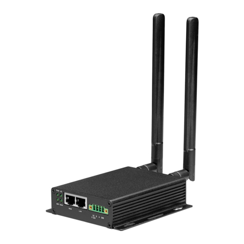
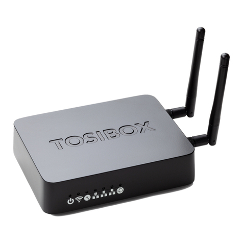
Tosibox Lock 150 User manual

1
Version 2.7
USER MANUAL
TOSIBOX®Lock 150
TOSIBOX®175
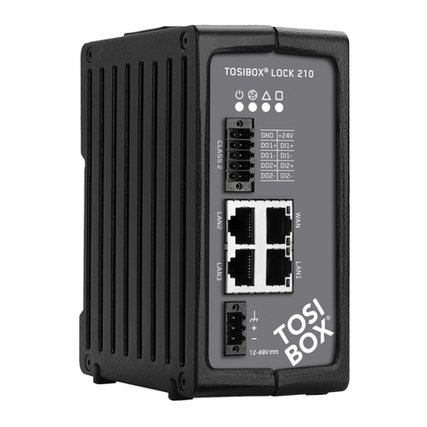
TOSIBOX®Lock 210
TOSIBOX®Lock 250
TOSIBOX®Lock 500
TOSIBOX®610
TOSIBOX®650
TOSIBOX®670
TOSIBOX®675
TOSIBOX®Key

2
TABLE OF CONTENTS
1. Regulatory information 4
1.1 TOSIBOX®Node intended use 4
1.2 Important notice for wireless operation of TOSIBOX®Node 4
1.3 Safety and hazards 5
1. Informations réglementaires 6
1.1 Utilisation prévue de TOSIBOX®Node 6
1.2 Avis important concernant le Fonctionnement
®Node 6
1.3 Sécurité et dangers 7
2. Overview to TOSIBOX® Key, Locks and Nodes 8
2.1 TOSIBOX®Key 8
2.2 TOSIBOX®Nodes 9
3. Getting started 11
4. TOSIBOX®Node instructions 12
4.1.1 Deploying Node in “Lock Mode” 12
4.1.2 Deploying Node in “Client Mode” 13
4.2 Connecting Nodes 14
4.3 Updating the Node Software 15
4.4 USB Modem settings for the Node 16
4.5 Internal modem settings 16
4.6 WLAN settings 16
4.7 Key connection settings for the Node 16
4.8 Advanced settings for the Node 17
4.9 Internet connection priorities 17
4.10 Service Port 17
4.11 Mounting instructions 18
4.12 Input powering options 20
4.13 Digital In/Out port with 24V DC out 22
4.15 Digital I/O SMS alert 24
5. TOSIBOX®Key instructions 26
5.1 Taking Master Key into use 26
5.2 Renaming and using devices 28
5.3 Adding extra Keys 30
5.4 Remote matching of extra Keys 35
5.5 PUK code for the Key 35
6. TOSIBOX®
7. Dépannage 37
8. Maintenance instructions 38
8. Consignes d’entretien 38
9. Technical data 39
10. Warranty 55
11. Legal Notices 56
11. Mentions légales 56
12. Declarations 57

3
Congratulations for choosing TOSIBOX®solution! It consists of modular
• TOSIBOX®Key is a client used to access the network.
• TOSIBOX®
In physical matching, the Key is inserted to the Lock’s USB port. The devices
trusted devices can access the network.
automatic security updates and the latest encryption technology.
TECHNICAL SUPPORT
FINLAND
+358 44 744 0065
Business hours:
from 8 am till 4 pm Mon – Fri
(UTC+2)
GLOBAL
+358 44 738 1778
Business hours:
from 8 am till 4 pm Mon – Fri
(UTC+2)
TOSIBOX GLOBAL SUPPORT
https://helpdesk.tosibox.com
VPN tunnel through Internet
TOSIBOX®
Mobile
Client
TOSIBOX®
Key
Firewall
TOSIBOX®
Lock
HMI
PLC
Camera
PC

4
1.1 TOSIBOX®NODE INTENDED USE
The Lock is used for controlling other devices remotely
requirements is guaranteed only when using the antennas
supplied with the product. The use of other antennas will
void the conformity and is not allowed.
the geographical area within a radius of 20 km from the centre of
the geographical area within a radius of 20 km from the centre of
1.2 IMPORTANT NOTICE FOR WIRELESS
OPERATION OF TOSIBOX®NODE
Because of the nature of wireless communications,
losses of data are rare when wireless devices are used in a
®
where failure to transmit or receive data could result in
damage of any kind to the user or any other party, including
damages of any kind resulting from delays or errors in data
transmitted or received using TOSIBOX®Node with cellular
modem, or for failure of the TOSIBOX®Node with cellular
modem to transmit or receive such data.
1. REGULATORY INFORMATION

5
1.3 SAFETY AND HAZARDS
Do not operate your Node with internal or external cellular
modem:
•
•
refuelling points, fuel depots, and chemical plants
• Near medical equipment, life support equipment, or any
interference. In such areas, the Node and the cellular
modem MUST BE POWERED OFF. Otherwise, the cellular
modem can transmit signals that could interfere with this
equipment.
• In an aircraft, the Node and the cellular modem MUST
BE POWERED OFF. Otherwise, the Node and the cellular
modem can transmit signals that could interfere with various
the aircraft or disrupt the cellular network. Use of a cellular
while the aircraft is on the ground and the door is open. The
time.

6
1.1 DOMAINE D’APPLICATION DU TOSIBOX®
NODE
Le Lock permet de contrôler des équipements distants
à travers Internet en créant une connexion VPN. Il peut
être installé sur un rail DIN dans une armoire à côté des
équipements à contrôler. Il peut aussi être posé sur ses patins
des caractéristiques de l’équipement est seulement garantie
avec l’installation des antennes livrées. L’utilisation d’autre
antenne annulera la conformité et n’est pas autorisée.
n’est pas autorisée dans une zone géographique située dans un
industriel léger
n’est pas autorisée dans une zone géographique située dans un
industriel léger
n’est pas autorisée dans une zone géographique située dans un
1.2 INFORMATION IMPORTANTE POUR
L’UTILISATION DU RÉSEAU SANS FIL DU
TOSIBOX®NODE
données transmises et reçues ne peuvent être garanties.
les retards de données soient rares lorsque les équipements
sont utilisés dans des conditions normales dans des réseaux
®Node avec
un modem cellulaire ne devrait pas être utilisé dans les cas
où les erreurs de transmission ou de réception de données
pourraient entrainer des dommages de quelque nature que ce
soit pour l’utilisateur ou pour une tierce partie, incluant mais
résultant de retards ou d’erreurs dans les données transmises
ou reçues en utilisant un TOSIBOX®Node avec modem
®
Node avec modem cellulaire lors de transmission ou réception
de ces données.
1. INFORMATIONS RÉGLEMENTAIRE

7
1.3 SÉCURITÉ ET DANGERS
Une distance minimale de 20 cm entre les antennes et les
personnes doit être respectée à tout moment.
N’utilisez pas votre Node avec un modem cellulaire interne ou
externe :
• Dans les zones des explosions sont est en cours
•
• À proximité d’équipements médicaux, d’équipements de
forme d’interférence radio. Dans ces zones, le Node et le
modem cellulaire DOIVENT ÊTRE ÉTEINTS, sous peine
d’interférer avec ces équipements.
• Le Node et le modem cellulaire DOIVENT ÊTRE ÉTEINTS
dans un avion. Le Node et le modem cellulaire sont
fonctionnement de l’appareil ou interférer avec les réseaux
radio.
• L’utilisation d’un téléphone cellulaire dans un avion est
de téléphonie cellulaire pour le contrevenant, ou des
aériennes peuvent autoriser l’utilisation de téléphones
cellulaires lorsque l’avion est au sol et que la porte est
ouverte. Le Node et le modem cellulaire peuvent être utilisés
normalement à ce moment.

8
2.1 TOSIBOX®KEY
TOSIBOX®
contains a secure cryptoprocessor. The Key is used to
TOSIBOX®Keys
SUB KEY
An additional Key that has restricted access rights.
BACKUP KEY
Key and the Backup Key.
see TOSIBOX®Node devices which are matched with the TOSIBOX®Key
and the network devices connected to each TOSIBOX®Node.
2. OVERVIEW TO TOSIBOX® KEY AND NODES (LOCKS)

9
2.2 TOSIBOX®
TOSIBOX®Node is a device that accepts remote
connections from matched Keys and creates private and
secure access to connected network devices. The network
devices that are connected to the Node´s LAN port are
TOSIBOX®VPN connection local network
SUB NODE
Node mode. When connecting two Nodes to each other,

10
LOCK USER INTERFACE
general information.
Locks and Keys
Green: Connected
Red: Disconnected
Remotely controlled
devices
Green: Connected
Red: Disconnected
Login using “admin”
user.
Password can
Details of the
remotely controlled
devices

11
3. GETTING STARTED
1. 2.
3. 4.
5.
proceeding to matching the Key with
the Node. Insert the Key into the USB
port of the Node. When the LED on the
Key from the Node. You can also match
additional Nodes to the same Key.
to make sure that the Node has a working
internet connection.
4. Connect the Key to your computer and
install the Key software. Follow the section
”Deploying the Key”.
5. Secure TOSIBOX connection is now ready
devices remotely.
THE FIRST DEPLOYMENT

12
With its factory default settings, the Node is connected to
the Internet via its WAN port or a USB modem which can
the Node creates its own protected local network for the
Note:
•
connect a USB modem to the Node´s USB port.
•
Node.
CONNECTING NETWORK DEVICES TO THE NODE
4.1.1 DEPLOYING NODE IN “LOCK MODE”
1. Before connecting device to Node, connect to device per
device manufacturer’s instructions on your PC and assign a
IP address. We recommend adding the next IP sequential
address ABOVE the IP address on the Node, and so forth
2.
1.
2. Connect your PC to the Node´s service port and log in
following the step 1 on page 17 “Updating the Node
software”.
3.
device and change it if necessary.
4.
5. ADVANCED/ENTERPRISE USERS ONLY: Go to
that it’s higher than all used static addresses. Set the limit
unused addresses in the LAN range. For example, the range
192.168.5.50 – 192.168.5.254 contains 205 addresses so
4. TOSIBOX®LOCK INSTRUCTIONS
VPN tunnel through Internet
TOSIBOX®
Mobile
Client
TOSIBOX®
Key
Firewall
TOSIBOX®
Lock
HMI
PLC
Camera
PC

13
4.1.2 DEPLOYING NODE IN “CLIENT MODE”
provides remote users with access to other devices in the
DHCP, so the local network needs to have a working DHCP
server that allocated IP addresses.
1.
2.
3.
Node´s LAN ports and go!
4.
Note:
• Do no connect the controlled devices to any LAN port.
• The Node will scan the entire LAN network for connected
devices and will grant device access to any user with a matched
Key. Please keep this in mind when considering network and
information security.
•
•
devices in the LAN network.
VPN tunnel through Internet
PC
TOSIBOX®
Key
Server
PC/Laptop
Printer
PC
TOSIBOX®
Lock
Router
L
A
N

14
4.2 CONNECTING NODES
With TOSIBOX®Nodes one can connect machines in
is permanently and automatically on. One example is
•
• TOSIBOX®
Nodes
•
•
• TOSIBOX®
Nodes
• TOSIBOX®
Nodes
• TOSIBOX®
Nodes
• TOSIBOX®
Nodes
®Key and
Node setup”.
CONNECTING NODES
1. Insert a matched Key to the USB port of the computer.
2. Choose ”Devices” from the Key user menu and ”Connect
Nodes” from the drop down menu.
3. Choose the Locks that you want to connect together and
choose ”Next”.
4.
mode.
5.
Nodes have access to the Internet.
connect to the Internet and each other.

15
Lock
Sublock Sublock Sublock
4.3 UPDATING THE LOCK SOFTWARE
a. Connect the computer to the service port of the Node
“http://” in the address.
1. Log in using “admin” for the user ID. The default admin
2.
3.
Do not interrupt the power of the Node during the software
update process. The update is complete when the software
gives a notice “Software updated successfully”.
Automatic software updates are activated as a default
setting. You can select the time when the automatic update
of the released software is allowed. You can deactivate the
automatic software update from the Node user interface.
4.
Sub Lock Sub Lock Sub Lock

16
4.4 USB MODEM SETTINGS FOR THE NODE
You can connect the Node to the Internet with a USB
Modem. For information on supported modems go to
.
1.
2.
operator.
3.
4.
of the Node.
4.5 INTERNAL MODEM SETTINGS
Supported on models TOSIBOX®175, Lock 500, TOSIBOX®
670 and TOSIBOX®675.
You can connect the Node to the Internet with an internal
disconnect the Node power supply.
1.
2.
operator.
3.
4.6 WLAN SETTINGS
Supported on models Lock 150, TOSIBOX®175, Lock 250,
Lock 500, TOSIBOX®650 and TOSIBOX®675.
up instructions visit .
4.7 KEY CONNECTION SETTINGS FOR THE
NODE
On Layer 2 connections you can allow connections from Node
to Key. Log into the Node
and Nodes
For more details on Layer 2 and Layer 3 connections visit
.

17
4.8 ADVANCED SETTINGS FOR THE NODE
Internet access restrictions and security related settings as
well as time zone and NTP server settings. NTP settings are
1. Log in as admin
2.
3.
4.9 INTERNET CONNECTION PRIORITIES
Node:
1. WAN
2. USB modem
3.
4.
is interrupted, the connection is automatically shifted to
again.
4.10 SERVICE PORT
On TOSIBOX®175 LAN port 1 and on Lock 210, Lock 250,
Lock 500, and on TOSIBOX®
the device.

18
4.11 MOUNTING INSTRUCTIONS
LOCK 150 QUICK INSTALLATION TO DIN RAIL
quick installation to DIN rail with the LAN/WAN ports facing
upwards.
LOCK 150 SECURE INSTALLATION TO DIN RAIL
is needed or another installation orientation is wanted, the
included in the sales package. There are M4 threaded
has the hole locations indicated. Use only the screws
included in the sales package. Using longer screws pose
a risk of damaging the device internal electronics. More
versatile installation options to DIN rail, such as angle
LOCK 150 WALL MOUNTING
countersunk screws.

19
LOCK 210, LOCK 250 AND LOCK 500 INSTALLATION
ON THE TABLE
The Node
designed to provide cooling air passing through the device.
Allow enough free space, minimum of 25mm around the
Node
Make sure there is no risk of the device falling aside as this
make the Lock fall aside and routed as far away from the
pattern, i.e. in such a way that they form 90 degrees angle
To achieve the maximum radio performance, follow the
antenna pattern shown in the picture on the next page.
Avoid installing the Node
Node. Also avoid installing the Node close to any sensitive
Node. In case of unwanted
Node in a place

20
Picture 8. Lock 500i installed
to DIN rail. See the antenna
directions.
1. Place the
slider under the
lower edge of the
DIN rail.
2. Push the Lock
upwards until the
slider travel is in
the end
3. Push the upper
edge of Lock
parallel to the wall
4. Slide the Lock
down and check
that the DIN rail
grip of the DIN rail
4.12 INPUT POWERING OPTIONS
LOCK 150
Use the AC adapter included in the sales package.
plug.
TOSIBOX®175
Use the AC adapter included in the sales package.
plug.
Other manuals for Lock 150
3
This manual suits for next models
9
Table of contents
Other Tosibox Network Router manuals
Popular Network Router manuals by other brands

Bivocom
Bivocom TR341-G user guide

Genesis
Genesis Pure E600 installation guide
TP-Link
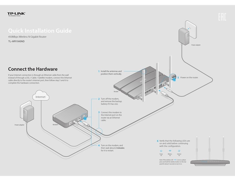
TP-Link TL-WR1043ND - Ultimate Wireless N Gigabit... Quick installation guide
Cudy
Cudy LT450 user manual

Huawei
Huawei B2368 quick start guide

Ruckus Wireless
Ruckus Wireless Ruckus ICX 7150 Series Hardware installation guide
