manuals.online logo
Brands
  1. Home
  2. •
  3. Brands
  4. •
  5. Wieland
  6. •
  7. Network Router
  8. •
  9. Wieland wienet UMS 5-L User manual

Wieland wienet UMS 5-L User manual

Montageanleitung (Original)/ Installation instruction (translation from original)
wienetIPSWITCH
UMS 5-L 83.040.0129.1
UMS 5G-L 83.040.0130.1
Unmanaged Ethernet Switch mit 5 Ethernet-Ports / with 5 Ethernet ports
Wieland Electric GmbH
Brennerstraße 10
– 14
96052 Bamberg
Phone
+49 9519324-0
Fax
+49 9519324-198
i
nfo@wieland-electric.com
www.wieland-electric.com
Doc. # BA001242 – 01/2021 (Rev. A) wienet IP SWITCH UMS 5-L / UMS 5G-L 1 DE / EN
HINWEIS
Personal, welches dieses Gerät installiert, programmiert, in Betrieb nimmt oder wartet,
muss diese Anleitung gelesen und verstanden haben.
WARNUNG
•Das Personal muss gründlich mit allen Warnungen, Hinweisen und Maßnahmen gemäß
dieser Montageanleitung vertraut sein.
•Ggf. erforderliche Schutzmaßnahmen und Schutzeinrichtungen müssen den gültigen
Vorschriften entsprechen.
•Beschädigte Produkte dürfen weder installiert noch in Betrieb genommen werden.
•Das Gerät darf nicht geöffnet werden.
•Führen Sie keine Fremdobjekte in das Gerät ein!
•Halten Sie das Gerät von Wasser und Feuer fern!
Weitere Beschreibungen finden Sie im Internet unter www.wieland-electric.com
1Funktionsbeschreibung
Das Gerät ist ein Unmanaged Ethernet Switch mit fünf RJ45-Schnittstellen für industrielle
Anwendungen und kann in industrieller Umgebung eingesetzt werden.
HINWEIS
Verwenden Sie das Gerät nur gemäß seiner Bestimmung. Beachten Sie dazu insbesondere
die Angaben im Abschnitt "Technischen Daten".
2Funktionselemente und Anzeigen
Pinbelegungen und Verbindungen
RJ45
10 / 100 BASE-T (X)
Pin
1
2
3
4
5
6
7
8
Signal
Tx+
Tx-
Rx+
Rx-
1000 BASE-T
Pin
1
2
3
4
5
6
7
8
Signal
BI_DA+
BI_DA-
BI_DB+
BI_DC+
BI_DC-
BI_DB-
BI_DD+
BI_DD-
Versorgungs-/ Signalanschlüsse
Pin
V2+
V2-
V1+
V1-
F.G.
Signal
12–48 VDC,
0 V
12–48 VDC
0 V
⏚
LEDs
Name
LED
Status
Beschreibung
P1/P2 grün

Stromversorgung P1,P2 nicht angeschlossen

Stromversorgung P1,P2 istaktiv
ALM rot

Kein Fehler oder Gerät AUS

Fehler (fehlende Spannung P1 oder P2)
RJ45
grün

Nicht an Netzwerk angeschlossen
•
Datenübertragung

Netzwerk angeschlossen
gelb

Nicht an Netzwerk angeschlossen oder an Netzwerk mit
10 Mbps angeschlossen
•
Datenübertragung

Netzwerk angeschlossen (100/1000 Mbps)
= aus; = an;•= blinkt
NOTE
Personnel which installs, programs, operates or maintains this device must have read and
understood these instructions.
WARNING
•The personnel must be thoroughly familiar with all warnings, notes and procedures
described in these installation instructions.
•
Where necessary, safety precautions and safety devices must comply with the applicable
regulations.
•Damaged products must neither be installed nor put into operation.
•The unit must not be opened.
•Do not insert any objects into the unit!
•Keep the unit awayfrom fireand water!
Additional information can be found at www.wie land-electric.com
1Function description
The device is a n unmana ged Ethernet swi tch with five RJ45 ports for industrial applications
and can be used in industrial environment.
NOTE
Use the device only as intended. Especially observe the specifications in the s ect ion
"Technical data".
2Functional elements and indicators
Pin assignments and connections
RJ45
10 / 100 BASE-T (X)
Pin
1
2
3
4
5
6
7
8
Signal
Tx+
Tx-
Rx+
Rx-
1000 BASE-T
Pin
1
2
3
4
5
6
7
8
Signal
BI_DA+
BI_DA-
BI_DB+
BI_DC+
BI_DC-
BI_DB-
BI_DD+
BI_DD-
Power connectors
Pin
V2+
V2-
V1+
V1-
F.G.
Signal
12–48 VDC,
0 V
12–48 VDC
0 V
⏚
LEDs
Name
LED
Status
Description
P1/P2 green

Power input P1, P2 is inactive

Power input P1, P2 is active
ALM red

No Error or deviceis OFF

Error (no voltageP1 or P2)
RJ45
green

Not connected to network
•
Data is transmitting

Connected to network
yellow

Connected to networkat 10 Mbps or not linked
•
Data is transmitting

Connected to network (at 100/1000Mbps)
= off; = on;•= flashes
1
2
3
4
5
Montageanleitung (Original)/ Installation instruction (translation from original)
wienetIPSWITCH
UMS 5-L 83.040.0129.1
UMS 5G-L 83.040.0130.1
Unmanaged Ethernet Switch mit 5 Ethernet-Ports / with 5 Ethernet ports
Wieland Electric GmbH
Brennerstraße 10
– 14
96052 Bamberg
Phone
+49 9519324-0
Fax
+49 9519324-198
i
nfo@wieland-electric.com
www.wieland-electric.com
Doc. # BA001242 – 01/2021 (Rev. A) wienet IP SWITCH UMS 5-L / UMS 5G-L 2 DE / EN
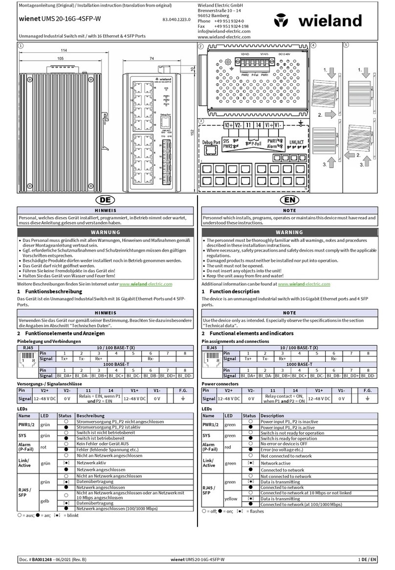
3Installation
Anbringen auf Trägerschiene (Bild 4)
1. Öffnen Sie die Halterungen oben und unten auf der Rückseite des Switch.
2. Rasten Sie den Switch auf der Hutschiene ein.
3. Schließen Sie die Halterungen oben und unten am Switch.
4. Prüfen Sie, ob das Gerät fest auf der Tragschiene sitzt.
Anschluss an Spannungsversorgung
•Geeignete Spannungsversorgungan wi en et Switch anschließen.
•Anschluss zweier separater Stromquellen für eine redundante Spannungsversorgung (P1,
P2) möglich.
Anschluss von Netzwerkgeräten
Schließen Sie Ihre Netzwerkgeräte über Standard-UTP/STP-Kabel mit RJ45 Steckverbindern
an den w ienet Switch an.
4Demontage (Bild5)
WARNUNG
Schalten Sie die Spannungsversorgung aus und trennen Sie das Gerät vom Netz.
Öffnen Sie die Halterungen oben und unten auf der Rückseite des Switch und nehmen Sie
das Gerät von der Hutschiene.
5Technische Daten
WARNUNG
•Verwenden Sie nur Kabel mit mindestens AWG 20 am Stromanschluss, die auf eine
Betriebstemperatur bis 85 °C ausgelegt sind.
•Das Gerät muss in einem Gehäuse vom Typ 1 insta lliert werden.
Switch-Eige nschaf ten
UMS 5-L
UMS 5G-L
Übertragungsart
Teilstreckenverfahren (Store and Forward)
MAC-Adresstabelle
1 K
8 K
Paketpuffer-Größe
448 KB
1 Mb
Jumbo Frame
–
10 KBytes
Ethernet
Anschlüsse: RJ45
10/100 Base-T(X)
10/100/1000Base-T(X)
Übertragungsrate (RJ45)
10/100 Mbps
10/100/1000Mbps
Übertragungsstandard
IEEE 802.3(10BaseT)
IEEE 802.3x (Flow Control, back pressure flow control)
IEEE 802.1q/p (VLAN Tagging and Class of Service)
IEEE 802.3az(Energy Efficient Ethernet)
IEEE 802.3u (100BaseT(X)
a
nd 100BaseFX)
IEEE 802.3u (100BaseT(X))
IEEE 802.3ab (1000BaseT)
IEEE 802.3z (1000BaseX)
Auto MDI/MDI-X
ja
Spannungsversorgung
Redundante Einspeisung
ja (P1, P2)
Eingangsspannungsbereich
12 – 48 V
Eingangsstrom max.
0,3 A
Allgemeine Daten
Betriebsumgebungstemperatur
-40 …+75 °C
0 …+60 °C
Relative Luftfeuchte
5 …95% RH, 55 °C keine Kondensation
Lagertemperatur
-40 …+85 °C
-20 …+70 °C
Montageauf
DIN Hutschiene 35 mm (EN 60715)
Schutzart
IP30
MTBF
20 Jahre(bei 25 °C)
Gewicht
ca. 110 g
Gehäusematerial
Plastik, schwarz
Schock und Vibration
Schock, Vibration, Freier Fall
IEC60068-2-27 / IEC 60068-2-6 / IEC60068-2-32
Anschlusstechnik
Anschlusstechnik
"Push In" Klemme, 5-pol.
Anschlussvermögen
0,25 …2,5 mm² (AWG 26 – AWG 12)
Abisolierlänge
8 – 9 mm
Normen und Zulassungen
EMV
EN55032,EN61000-6-4, EN 550 24, EN 61000-6-2 ,
EN61000-3-2, EN61000-3-3
Sicherheit
UL/IEC62368-1
FCC
FCC Part 15, SubpartB,ClassA
Zulassung
CE, cULus, FCC
3Installation
Mounting on support rail (see fig. 4)
1. Open the mounting brackets on the back of the switch.
2. Snap the switch in place on the DIN rail.
3. Close the mounting brackets on the switch.
4. Check that theunit is locked into position.
Connecting to power
•Prepare a suitable power source and connect to the wi enet switch.
•You can connect two independent DC input sources for power auto-backup if necessary
(P1, P2).
Connecting to network device by Ethernet
Connect your device by standard UTP/STP cable with RJ45 connectors to the wienet switch.
4Removal from DIN rail (see fig. 5)
WARNING
Switch mains power off and disconnect the device from the supply network.
Open the mounting brackets on the back of the switch and take the device off the rail.
5Technical data
WARNING
•It is recommended to use at least 20 AWG cables. The cables need to be resistant to at
least 85 °C on the power connector.
•The device needs to be installed inside a type 1 housing.
Switch Properties
UMS 5-L
UMS 5G-L
Processing Scheme
Storeand Forward
MAC Address Table
1 K
8 K
Packet Buffer Size
448 KB
1 Mb
Jumbo Frame
–
10 KBytes
Ethernet
Connectors: RJ45
10/100 Base-T(X)
10/100/1000Base-T(X)
Transfer rate (RJ45)
10/100 Mbps
10/100/1000Mbps
Ethernet standard
IEEE 802.3(10BaseT)
IEEE 802.3x (Flow Control, back pressure flow control)
IEEE 802.1q/p (VLAN Tagging and Class of Service)
IEEE 802.3az(Energy Efficient Ethernet)
IEEE 802.3u (100BaseT(X)
and 100BaseFX)
IEEE 802.3u (100BaseT(X))
IEEE 802.3ab (1000BaseT)
IEEE 802.3z (1000BaseX)
Auto MDI/MDI-X
yes
Power supply
Redundant power supply
yes (P1, P2)
Dual input voltage
12 – 48 V
Input current max.
0.3 A
General data
Ambient operating temperature
-40 …+75 °C
0 …+60 °C
Ambient relative humidity
5 …95% RH, 55 °C non-condensing
Storage temperature
-40 …+85 °C
-20 …+70 °C
Mounting on
DIN rail 35 mm (EN 60715)
Degree of protection
IP30
MTBF
20 years (at 25 °C)
Weight
approx. 110 g
Housing material
plastic, black
Shock and vibration
Shock, vibration, free fall
IEC60068-2-27 / IEC 60068-2-6 / IEC60068-2-32
Connectors
Wiring
"Push In" terminal, 5 pin
Rated conductor size
0.25 … 2.5 mm² (AWG 26 – AWG 12)
Conductor strip length
8 – 9 mm
Norms and approvals
EMC
EN55032, EN 61000-6-4, EN 55024, EN 61000-6-2,
EN61000-3-2, EN61000-3-3
Safety
UL/IEC62368-1
FCC
FCC Part 1 5, Subpa rt B, Class A
Approval
CE, cULus, FCC

This manual suits for next models

3

Other Wieland Network Router manuals

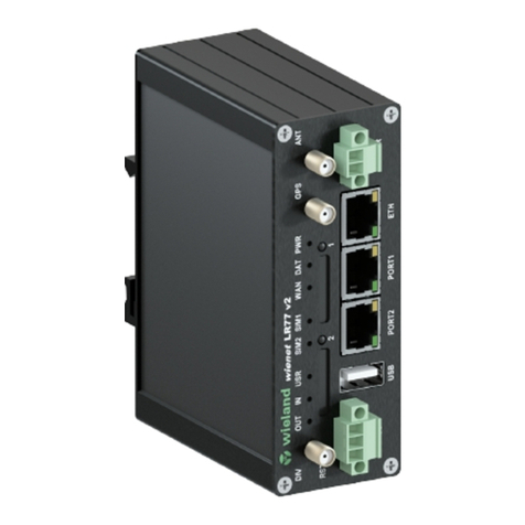
Wieland wienet router v2 Instruction sheet

Wieland

Wieland wienet router v2 Instruction sheet

Wieland 83.041.0050.1 User manual

Wieland

Wieland 83.041.0050.1 User manual

Wieland WIENET LAN WR V3 SL User manual

Wieland

Wieland WIENET LAN WR V3 SL User manual

Wieland wienet router v2 User manual

Wieland

Wieland wienet router v2 User manual

Wieland wienetUMS 8-4POE-W User manual

Wieland

Wieland wienetUMS 8-4POE-W User manual

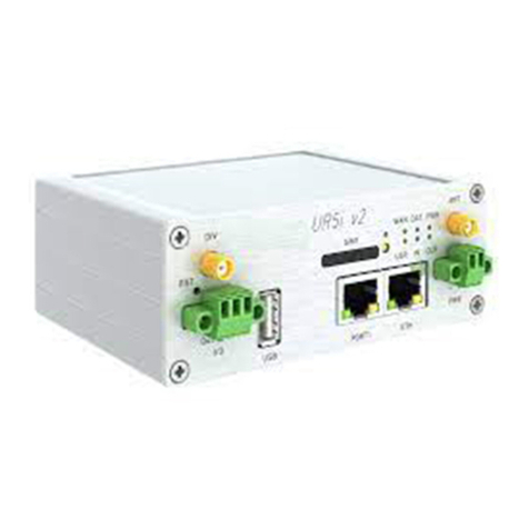
Wieland Wienet UR5i User manual

Wieland

Wieland Wienet UR5i User manual

Wieland wienet UMS 20-16G-4SFP-W User manual

Wieland

Wieland wienet UMS 20-16G-4SFP-W User manual

Wieland LAN ER300 GLOBAL User manual

Wieland

Wieland LAN ER300 GLOBAL User manual

Wieland 83.041.0665.3 User manual

Wieland

Wieland 83.041.0665.3 User manual

Wieland wienet LMS 16-W User manual

Wieland

Wieland wienet LMS 16-W User manual

Wieland xr5i v2 User manual

Wieland

Wieland xr5i v2 User manual

Wieland wienet WR-LTE v3 SL User manual

Wieland

Wieland wienet WR-LTE v3 SL User manual

Popular Network Router manuals by other brands

D-Link DIR-879 Quick install guide

D-Link

D-Link DIR-879 Quick install guide

Blueone Technology HJ8400 Web Configuration User Manual

Blueone Technology

Blueone Technology HJ8400 Web Configuration User Manual

AudioCodes M500Li Configuration guide

AudioCodes

AudioCodes M500Li Configuration guide

Asus WL-500gP quick start guide

Asus

Asus WL-500gP quick start guide

City-Netek CN-1108 Setup and installation manual

City-Netek

City-Netek CN-1108 Setup and installation manual

Linksys MAX-STREAM EA8100 V2 Regulatory information

Linksys

Linksys MAX-STREAM EA8100 V2 Regulatory information

TP-Link AC1900 user guide

TP-Link

TP-Link AC1900 user guide

Wenshing RD-485 instruction manual

Wenshing

Wenshing RD-485 instruction manual

Netopia Cayman 3386-ENT quick start guide

Netopia

Netopia Cayman 3386-ENT quick start guide

LevelOne NetCon FBR-1415TX user manual

LevelOne

LevelOne NetCon FBR-1415TX user manual

Datalogic Modem quick reference

Datalogic

Datalogic Modem quick reference

Allen-Bradley 1783-NATR Product information

Allen-Bradley

Allen-Bradley 1783-NATR Product information

MicroNet EtherFast SP624EA Quick installation guide

MicroNet

MicroNet EtherFast SP624EA Quick installation guide

Cisco ASR 1002-X Overview and installation

Cisco

Cisco ASR 1002-X Overview and installation

Technicolor TG589 Wireless networking guide

Technicolor

Technicolor TG589 Wireless networking guide

Siemens N 146 Operating and mounting instructions

Siemens

Siemens N 146 Operating and mounting instructions

RouterBOARD Metal 5SHPN Quick setup guide and warranty information

RouterBOARD

RouterBOARD Metal 5SHPN Quick setup guide and warranty information

D-Link DES-3550 Command line interface reference manual

D-Link

D-Link DES-3550 Command line interface reference manual

manuals.online logo
manuals.online logoBrands
  • About & Mission
  • Contact us
  • Privacy Policy
  • Terms and Conditions

Copyright 2025 Manuals.Online. All Rights Reserved.