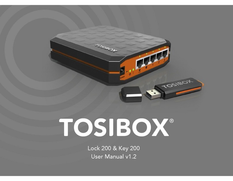
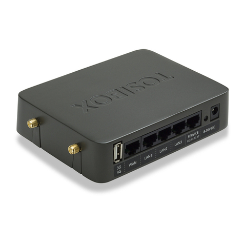
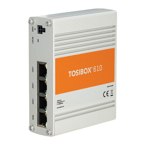
Tosibox Lock 100 User manual

Copyright ©Tosibox Oy 2014
User Manual v2.9

2Table of Contents
Tosibox in brief 3
Tosibox connections - Lock Mode A 4
Tosibox connections - Lock Mode B 5
Tosibox glossary 6
Tosibox products and accessories 7
Key user interface 8
Lock user interface 9
Tosibox Key and Lock serialization 11
Taking the Lock into use - Mode A 13
Taking the Lock into use - Mode B 15
Taking the Key into use 17
Renaming and use of the devices 19
Taking extra Keys into use 21
Remote serialization of extra Keys 23
Creating a Backup Key 25
Connecting Locks 27
Logging in to Lock 28
Software update 30
3G modem for the Lock, Key connection settings for the Lock 31
Industry settings of the Lock 32
Lock Wireless settings 33
Internet connection priorities 34
PUK code for the Key 36
Problem situations 37
Maintenance instructions 38
Tosibox – technical data - Lock 39
Tosibox – technical data - Key 40
Tosibox licences 41
Declaration of Conformity 42
Sisällysluettelo
Tosibox lyhyesti 3
Tosibox liitännät - Lock Mode A 4
Tosibox liitännät - Lock Mode B 5
Tosibox sanastoa 6
Tosibox tuotteet ja tarvikkeet 7
Avaimen käyttöliittymä 8
Lukon käyttöliittymä 9
Avaimen (Key) ja lukon (Lock) sarjoitus 11
Lukon käyttöönotto – Mode A 13
Lukon käyttöönotto – Mode B 15
Avaimen käyttöönotto 17
Laitteiden nimeäminen ja käyttäminen 19
Lisäavainten käyttöönotto 21
Lisäavainten etäsarjoitus 23
Vara-avaimen luonti 25
Lukkojen yhdistäminen 27
Lukkoon kirjautuminen 28
Ohjelmiston päivitys 30
Lukon 3G-modeemi -asetukset, Lukon avainyhteysasetukset 31
Lukon Industry-asetukset 32
Lukon Wireless-asetukset 33
Internetyhteyksien prioriteetit 34
Avaimen PUK-koodi 36
Ongelmatilanteet 37
Huolto-ohjeita 38
Tosibox – technical data - Lock 39
Tosibox – technical data - Key 40
Tosibox-lisenssit 41
Vaatimustenmukaisuusilmoitus 42

3
Tosibox in brief
Tosibox oers a new, automatic way to establish a remote
connection easily, quickly and securely. Tosibox is a Plug & Go
remote access device. All you need to take it into use is mains
current and an internet connection.The operating principle of
Tosibox resembles that of a mechanical lock and key.
The product consists of a key device (Key) and a locking
device (Lock).The system is brought into use by serializing
the equipment physically through a USB port of the Lock. The
connection to the controlled network devices in the remote
location is opened with a Key that has been serialized to the
Lock.
Tosibox Locks and Keys that have been serialized to each other
will nd each other over internet and from separate local
networks regardless of how they are connected to the internet.
This allows the control of either network devices in the same
local network with the Lock (factory default setting ”Mode A”,
p.12-13) or the network devices directly connected to the Lock
(Lock setting ”Mode B”, p.14-15).
This User Manual is for Lock software version 2.10 and Key
software version 2.10. In case newer software version is used,
download the latest user Manual fromTosibox web site in:
www.tosibox.com/manual
Tosibox lyhyesti
Tosibox tarjoaa uudenlaisen, automaattisen tavan muodostaa
etäyhteys helposti, nopeasti ja turvallisesti.Tosibox on
kytke-ja-käytä menetelmään perustuva etäyhteyslaite, jonka
käyttöönotossa tarvitaan vain verkkovirtaa ja internet-liittymä.
Tosiboxin toimintaperiaate muistuttaa mekaanisen lukon ja
avaimen toimintaa.
Tuote koostuu avainlaitteesta (Avain tai Key) ja lukkolaitteesta
(Lukko tai Lock). Käyttöönotto tapahtuu sarjoittamalla laitteet
fyysisesti toisiinsa Lukon USB-portin kautta.Yhteys etäkohteen
ohjattaviin verkkolaitteisiin avautuu Lukkoon sarjoitetun
Avaimen avulla.
Toisiinsa sarjoitetut Lukot ja Avaimet löytävät internetistä
ja sen eri sisäverkoista toisensa täysin automaattisesti
riippumatta siitä, millä tavoin ne ovat yhdistettyinä internetiin.
Tällöin päästään ohjaamaan joko Lukon kanssa samassa
sisäverkossa olevia verkkolaitteita (Lukon tehdasasetus“Mode
A”, ohje s. 12–13) tai suoraan Lukkoon liitettyjä verkkolaitteita
(Lukon asetus“Mode B”, Ohje s. 14–15).
Tämä käyttöohje kuvaa Lukon ohjelmistoversiota 2.10
ja Avaimen ohjelmistoversiota 2.10. Jos käytössäsi on tästä
uudempia ohjelmistoversioita, lataa uusin käyttöohje
Tosiboxin verkkosivuilta osoitteesta:
www.tosibox.com/manual

4
DC Power Input
Reset Button (Not used)
Service Port
LAN3 Port (Connect this port
only to existing LAN)
Not used in Mode A
USB Port (Serialization only).
3G-Modem not allowed in
Mode A!
LAN3
Service
WLAN
Power
WLAN Antenna Ports
Lock Mode A

5
DC Power Input
Reset Button (Not used)
Service Port
LAN3 Port (Connect this port
only to existing LAN)
Not used in Mode A
USB Port (Serialization only).
3G-Modem not allowed in
Mode A!
LAN3
Service
WLAN
Power
Lock Mode B
DC Power Input
Reset Button (Not used)
Service Port
LAN3 Port
LAN2 Port
LAN1 Port
WAN Port
USB Port (Serialization
and 3G-Modem)
WAN
LAN1
LAN2
LAN3
Service
WLAN
Power
WLAN Antenna Ports
(Alternative option to connect to existing LAN)

6Tosibox glossary
Key = an intelligent, microprocessor using USB connected key
device that establishes a connection with the locking device.
Sub Key = Accessory Key that has restricted user rights.
Backup Key = a duplicated backup copy of the Key. All serializations
and user rights are automatically synchronized between the original
Key and the Backup Key.
Lock = a locking device that has two dierent modes of operation
(Mode A and Mode B). In Mode A the Lock automatically nds the
network devices in the same local network. In Mode B only the
network devices directly connected to the Lock´s LAN port are
automatically found.The Lock always automatically distributes the
IP-addresses for the Keys and Sub Keys and in Mode B also for the
network devices connected to LAN port of the Lock. The Lock can
also control network devices with xed IP address.
Sub Lock = a Lock that has been converted to Sub Lock mode
of operation.When connecting two Locks with each other one
of them has to be in Sub Lock mode of operation.
Lock Mode A = factory default setting of the Lock. The Lock is
connected to the existing local network via LAN3 -port.
Lock Mode B = Lock mode of operation in which the Lock
enters automatically if an ethernet cable is connected to the
WAN port of the Lock or a 3G modem is connected to the
USB port of the Lock. In Mode B the controlled devices are
connected to LAN1 – LAN3 ports of the Lock (either directly
or via extra switch) or alternatively to the wireless local
network (WLAN)of the Lock.
DHCP-server = Network device or software part of a network
device that distributes IP addresses to the other devices in the same
network
Tosibox-sanastoa
Key = Älykäs, prosessorin sisältävä USB-liitäntäinen avainlaite,
jonka avulla muodostuu yhteys lukkolaitteeseen.
Sub Key = Lisäavainlaite (Key), jonka käyttöoikeuksia on rajoitettu
ohjelmallisesti.
Backup Key = Vara-avain, Avaimesta tehty varmuuskopio. Kaikki
sarjoitukset ja oikeudet synkronoituvat automaattisesti alkuperäisen
Avaimen ja varmuuskopion välillä.
Lock = Lukkolaite, joka sisältää kaksi ohjelmallisesti erilaista
toimintatilaa (Mode A ja Mode B). Mode A -tilassa Lukko löytää
automaattisesti kaikki saman sisäverkon verkkolaitteet ja Mode
B -tilassa vain Lukon omaan LAN-liitäntään liitetyt verkkolaitteet.
Lukko jakaa automaattisesti IP-osoitteet aina Key- ja Sub Key
-avaimille sekä Mode B -tilassa myös Lukon omaan LAN-liitäntään
liitetyille verkkolaitteille. Lukolla voidaan ohjata myös verkkolaitteita,
joilla on kiinteä IP-osoite.
Sub Lock = Lukkolaite (Lock), joka on muutettu ohjelmallisesti
Sub Lock -tilaan.Yhdistettäessä kaksi Lukkoa keskenään,
toisen niistä on oltava Sub Lock -tilassa.
Lock Mode A = Lukon tehdasasetustoimintatila, jossa Lukko
liitetään olemassa olevaan sisäverkkoon LAN3-portin kautta.
Lock Mode B = Lukon toimintatila, johon Lukko siirtyy
automaattisesti, jos LockinWAN-porttiin kytketään
verkkokaapeli tai USB-porttiin kytketään 3G-modeemi.
Mode B:ssä ohjattavat laitteet kytketään Lukon LAN1-LAN3
portteihin (joko suoraan tai lisäkytkimen välityksellä), tai
vaihtoehtoisesti Lukon langattomaan lähiverkkoliitäntään
(WLAN).
DHCP-palvelin = Verkkolaite tai jonkun verkkolaitteen ohjelmallinen
osa, joka jakaa verkon laitteille IP-osoitteet.

7
Tosibox products and accessories:
Tosibox Lock Tosibox Key USB Cable
Ethernet Cable AC Adapter Antennas ( 2 )

8Tosibox Key
An intelligent, microprocessor using USB connected key
device that establishes a connection with the locking
device. For more information, please see glossary (page 6).
*Key user interface (installs from the Key). In the
picture on left are TOSIBOX®Lock devices which are
serialized for TOSIBOX® Key and network devices
connected into them. For more options click the
arrow icon button.
Tosibox Avain
Älykäs, prosessorin sisältävä USB-liitäntäinen avainlaite,
jonka avulla muodostuu yhteys lukkolaitteeseen.
Katso lisätiedot sanastosta (sivu 6).
*Avaimen käyttöliittymä (latautuu Avaimelta). Kuvan
vasemmassa reunassa Avaimelle sarjoitetut Lukko
-laitteet ja niihin kytketyt verkkolaitteet.
Avaa lisävalikko klikkaamalla nuolipainiketta.
Key user interface* / Avaimen käyttöliittymä*

9
Tosibox Lock
A locking device that has two dierent modes
of operation (Mode A and Mode B). For more
information, please see glossary (page 6).
*Web user interface for the Lock.
Changing
the Lock settings via:
• Service port
• Tosibox encrypted VPN connection
• Local network
Tosibox Lukko
Lukkolaite, joka sisältää kaksi ohjelmallisesti erilaista
toimintatilaa (Mode A ja Mode B). Katso lisätiedot
sanastosta (sivu 6).
*Lukon selainkäyttöliittymä.
Lukon asetusten
muuttaminen:
• Service portin kautta
• Tosibox-salatun VPN yhteyden kautta
• Sisäverkosta
Web user interface for the Lock* / Lukon verkkokäyttöliittymä*

10
1. 2.
3.
5.
4.
Tosibox Key and Lock Serialization

11
Tosibox Key and Lock serialization
1. Connect theTosibox AC adapter to the Lock and wait
for 2 minutes. Serialize the Key to the Lock by inserting
the Key into the USB port of the Lock. When the LED
on the Key stops blinking, the serialization is complete.
Remove the Key from the Lock.You can also serialize
several Locks to the Key. After the rst Key is serialized
to the Lock, the next Keys (Key or Sub Key) are serialized
with a computer. See section ”Taking extra Keys into
use, p.21”.
2. and 3.Take the Lock into use. Depending on your use
case select the Lock mode of operation Mode A or
mode B. Depending on what is connected to the Lock´s
ethernet ports , the operation mode is determined
automatically. See section ”Taking the Lock into use
-mode A, p.13”or ”Taking the Lock into use -mode B,
p. 14”. Make sure the Lock receives a working internet
connection.
4. Connect the Key to your computer and install the Key.
Follow the section ”Taking the Key into use”.
5. Tosibox connection is ready.You can use, control
and monitor remote objects.
Avaimen (Key) ja Lukon (Lock)
sarjoitus
1. KytkeTosibox-virtalähde Lukkoon ja odota 2 minuuttia.
Sarjoita Avain Lukkoon laittamalla Avain Lukon USB-
porttiin. Kun avaimen LED-valo lakkaa vilkkumasta,
sarjoitus on valmis. Irroita Avain Lukosta. Voit sarjoittaa
Avaimelle myös useita Lukkoja. Kun Lukkoon on
sarjoitettu ensimmäinen Avain, seuraavat Avaimet
sarjoitetaan tietokoneen avulla (Key/Sub Key). Katso
kohta ”Lisäavainten käyttöönotto, s 21 ”
2. ja 3. Ota Lukko käyttöön.Valitse Lukon toimintatilaksi
Mode A tai Mode B, riippuen käyttötarpeestasi. Lukon
toimintatila määräytyy automaattisesti sen mukaan
mitä Lukon ethernet-portteihin yhdistetään. Katso
kohta ”Lukon käyttöönotto – Mode A, s. 13”tai ”Lukon
käyttöönotto – Mode B, s. 15”. Varmista että Lukko saa
toimivan internetyhteyden.
4. Liitä Avain omaan tietokoneeseesi ja asenna Avain
ohjeen kohta ”Avaimen käyttöönotto”mukaisesti.
5. Tosibox yhteys on valmis.Voit käyttää, ohjata ja
valvoa etäkohteita.

12
LAN
TOSIBOX KEY
COMPUTER 1
COMPUTER 2
PRINTER
LAPTOP !
LAPTOP 2
SERVER
ETHERNET CABLE
TO THE LAN 3 PORT
INTERNET
SERVER
PRINTER
LAPTOP 1
TOSIBOX LOCK
LAPTOP 2
COMPUTER 2
COMPUTER 1
Lock Mode A

13
Taking the Lock into use –
Mode A
The Lock has two alternative mode of operation, Mode A
and Mode B.The mode is selected according to what is the
network environment and what is the using purpose of the
Lock. Factory default setting is mode A.
Mode A = Total Plug & Go, factory default setting.Tosibox Lock is
connected to become part of the existing network. In this case all
local network devices with both xed and dynamic IP-addresses
are visible in Lock user interface. With the Key an access for all
these devices can be obtained.
Note: Access to the devices can be limited with separate
MAC-lter functionality (industry setting)
For the Lock only power cord and local network ethernet
cable to Lock´s LAN3 -port is needed. Local network
or Lock settings do not need to be modied. Mode A
requires a DHCP server in the local network. In a functional
local network there is usually always a DHCP server that
distributes IP-addresses to the controlled devices and the
Lock.
Notice: -Do not connect internet to Lock´sWAN Port or a
3G modem to USB Port. Doing so will automatically switch
the mode of operation to Mode B! From Mode B the Lock
does not automatically return to Mode A.This needs to be
done by logging in to Lock´s user interface with admin user
ID (visible in the bottom of the Lock).
– Do not connect the controlled devices to Lock´s LAN
ports.
– The user of the Key has access to all devices in the local
network. Consider the data security.
– In case access rights need to be restricted, initiate MAC-
ltering (Industry-setting) or use Mode B.
Lukon käyttöönotto –
Mode A
Lukolla on kaksi vaihtoehtoista toimintatilaa, Mode
A ja Mode B.Toimintatila valitaan sen perusteella,
millaiseen verkkoympäristöön ja käyttötarkoitukseen
Lukko asennetaan.Tehdasasetuksena Lukko on Mode A
-toimintatilassa.
Mode A = Täydellinen Plug & Go, tehdasasetus.Tosibox Lukko
liitetään osaksi olemassa olevaa sisäverkkoa. Tällöin Lukon
käyttöliittymässä näkyvät kaikki sisäverkon verkkolaitteet, sekä
kiinteä- että vaihtuvaosoitteiset. Avaimen avulla saa yhteyden
näihin kaikkiin sisäverkon laitteisiin. Huom! Laitteisiin pääsyä
voit rajoittaa erillisellä MAC-lter -toiminnolla (industry-asetus)
Lukkoon tarvitsee liittää vain virtajohto ja sisäverkon
ethernetkaapeli Lukon LAN3-porttiin. Sisäverkon tai Lukon
asetuksia ei tarvitse muuttaa. Mode A vaatii toimiakseen
sisäverkossa olevan DHCP -palvelimen.Yleensä toimivassa
sisäverkossa on aina toimiva DHCP-palvelin joka jakaa IP-
osoitteet ohjattaville laitteille sekä Lukolle.
Huomioitavaa:
– Älä kytke verkkojohtoa LukonWAN-porttiin tai
3G-mokkulaa USB-porttiin, koska tällöin Lukon
toimintatila muuttuu automaattisesti Mode B:ksi! Mode
B:stä laite ei muunnu automaattisesti takaisin Mode A
-tilaan, vaan se on tehtävä kirjautumalla Lukon sisälle
sen käyttöliittymästä admin-tunnuksilla (löytyy laitteen
pohjatarrasta).
– Älä kytke ohjattavia laitteita Lukon LAN-portteihin.
– Avaimen käyttäjällä on pääsy kaikkiin sisäverkon laitteisiin.
Huomioi tietoturva.
– Mikäli käyttöoikeutta täytyy rajoittaa, ota käyttöön MAC-
suodatus (industry-asetus) tai ota käyttöön Mode B.

14
LAN
TOSIBOX KEY
COMPUTER 2
LAPTOP 2
SERVER INTERNET
SERVER
PRINTER
LAPTOP 1
LAPTOP 2
COMPUTER 2
COMPUTER 1
INTERNET CONNECTION
TO THE WAN PORT OR
3G MODEM
TO THE USB PORT
TOSIBOX LOCK
Taking the Lock into use –
Mode B
Mode B = Mode of operation that the Lock switches into
from Mode A, whenWAN-Port of the Lock is connected
with an internet or a 3G modem is connected into the
USB port of the Lock. In Mode B the Lock creates its own
protected local network from the connected devices. Only
these devices, connected to the Lock directly by cable or
wirelessly, are accessible with the Key
Note:
– Follow the section ”3G modem for the Lock”instructions
when connecting the 3G modem into the Lock´s USB
port.
– Mode B can be switched back to Mode A only with
admin user-ID from the Lock´s user interface.
– In case a Lock which is in mode B is connected from
Lock´s LAN port (LAN1, LAN2 or LAN3) to another local
network that has a working DHCP server, Lock´s own
LAN is disactivated. It is reactivated after the improper
connection is removed.
Taking into use the controlled devices with dynamic IP addresses:
In case all the controlled devices have dynamic IP addresses,
they will automatically connect to the Lock. In this case the LAN-
network is created in Plug & Go principle.
Taking into use the controlled devices with static IP addresses:
Note! When the Lock is in ”Mode A”and when there is a
DHCP service in the network, the Lock will automatically
nd also devices with xed IP address in the same network.
In other case:
1. Connect the computer into Lock´s Service Port. Type“http://
service.tosibox”or“172.17.17.17”into the web browser. The
user ID is ”admin”and the password is visible inthe bottom of
the Lock.
2. Go to Network > LAN and see the IP address of the Lock
from ”Ipv4 address”. Check also that the network mask in
”Ipv4 netmask”is set to 255.255.255.192.
3. Go to the settings of the controlled device. Set the device
into the same IP-address space than the Lock.
Lock Mode B

15
The fourth number of the IP address of the controlled
device shall be 1-9 upwards from the Lock´s IP addresses
fourth number. Set the network mask 255.255.255.192.
An example: Lock´s LAN address is 10.25.15.193.
In this case the rst controlled device´s IP address is
10.25.15.194.The next shall be 10.25.15.195 and so on.
4. Go to Lock settings. Set the controlled device´s IP
address (eg. 10.25.15.194) into Lock´s user interface with
”new network device”option. If needed, the device can
be renamed.You can also use ”Scan for LAN devices”
option to make the Lock immediately and automatically
nd the devices in the same network address space
Vaihtuvalla IP-osoitteella varustettujen laitteiden
käyttöönotto:
Mikäli kaikki ohjattavat laitteet toimivat vaihtuvalla IP-osoitteella, ne
yhdistyvät Lukkoon automaattisesti.Tässä tapauksessa LAN-verkko
muodostuu Plug & Go -periaatteella.
Kiinteällä IP-osoitteella varustettujen laitteiden
käyttöönotto:
Huom! Lukon ollessa ”Mode A”-tilassa ja kun verkossa
on DHCP-palvelu, Lukko löytää automaattisesti myös
saman verkon kiinteäosoitteiset verkkolaitteet. Muussa
tapauksessa:
1. Liitä tietokone Lukon Service-porttiin. Kirjoita
internetselaimeen“http://service.tosibox”tai
“http://172.17.17.17”. Käyttäjätunnus on“admin”
ja salasana on nähtävissä Lukon pohjassa.
2. Mene kohtaan Network > LAN > ja tarkista Lukon
IP-osoite kohdasta“IPv4 address”. Tarkista lisäksi että
verkkomaski kohdassa“IPv4 netmask”on asetettu
255.255.255.192.
3. Mene ohjattavan laitteen asetuksiin. Aseta laite samaan
osoiteavaruuteen kuin Lukon LAN siten, että ohjattavan
laitteen IP-osoitteen neljäs luku on Lukon IP-osoitteesta
1–9 seuraavaa ylöspäin. Aseta vielä verkkomaski
255.255.255.192. – Esimerkki: Lock LAN osoite on
10.25.15.193, tällöin ensimmäisen ohjattavan laitteen
IP-osoite on 10.25.15.194 ja seur. 10.25.15.195 jne.
4. Mene Lukon asetuksiin. Aseta ohjattavan laitteen IP-osoite
(esim. 10.25.15.194) Lockin käyttöliittymään ”new network
device”toiminnolla. Halutessasi voit myös nimetä laitteen
uudelleen.Voit käyttää myös ”Scan for LAN devices”-toimintoa,
jolloin Lukko löytää heti saman verkkoavaruuden laitteet
automaattisesti.
Lukon käyttöönotto – Mode B
Mode B = Toimintatila johon Lukko siirtyy Mode A:sta, kun
LukonWAN-porttiin liitetään internetyhteys tai USB-porttiin
liitetään 3G-modeemi. Mode B:ssä Lukko muodostaa
oman suojatun sisäverkon siihen liitettävistä laitteista.
Avaimen avulla saadaan yhteys vain näihin, Lukkoon suoraan
langallisesti tai langattomasti liitettyihin laitteisiin.
Huomioitavaa:
–Noudata ”Lukon 3G-modeemi asetukset”osion ohjeita kun
kytket 3G-modeemin Lukon USB-porttiin.
– Toimintatila voidaan palauttaa Mode B:stä mode
A:han vain admin -käyttäjätunnuksen avulla Lukon
käyttöliittymästä.
– Mikäli Mode B:ssä oleva Lukko yhdistetään Lukon LAN-
liitännästä (LAN1, LAN2 tai LAN3) muuhun sisäverkkoon,
jossa on jo toimiva DHCP-palvelu, Lukon oma LAN-verkko
lakkaa toimimasta. Lukon oma LAN-verkko palautuu
toimivaksi, kun väärä kytkentä poistetaan.

16
1. Taking the Key into use
2. Set password
3. Key user interface

17
Taking the Key into use
1. Insert the serialized Key into the USB -port of your computer.
Start“Setup_Tosibox”executable from the“Autoplay window
that opens on the desktop. If your computer asks whether you
allow tosibox to make changes, click allow. Key setup starts.
After the setup close the setup window by choosing ”close”.
2. The Key will ask for a password which you can enter, if
you wish (recommended). By entering a password, you
can prevent the unauthorized use of the Key. Store the
password safely.
3. Key opens up a window that shows the Locks that have
been serialized to the Key. Connect the Key with the
wanted Lock by clicking the“Connect”icon of this Lock.
4. Key info dialogue shows the status of the connection
establishment between the Key and the Lock.
Taking the Key into use is ready.
The Lock symbol is shown with dierent colour according
to the operating status of the Lock:
– Red = Lock is not connected to the internet
– Yellow = Lock and Key have detected each other but
the connection with the Lock and Key has not yet been
established
– Green = Encrypted connection between Key and Lock is
ready
The Key symbol in the task bar of the computer is shown
withdifferentcolour accordingtotheoperating statusofthe Key:
– Red = Key has not reached a connection to the internet
– Yellow = Key has access to internet and found at least one
Lock but none of the Locks are yet connected to the Key
– Green = Key has made an encrypted connection to at least
one Lock
Avaimen käyttöönotto
1. Aseta sarjoitettu Avain tietokoneen USB-porttiin. Käynnistä
työpöydälle avautuvasta“Autoplay”-ikkunasta“Setup_Tosibox”
-niminen suoritustiedosto. Jos tietokoneesi kysyy sallitko
tosiboxin tehdä muutoksia > klikkaa salli. Avaimen asennus
käynnistyy. Asennuksen jälkeen sulje asennusikkuna
valitsemalla ”close”.
2. Avain kysyy salasanan, jonka voit tässä vaiheessa syöttää
(suositus). Asettamalla salasanan voit estää Avaimen
luvattoman käytön.Talleta salasana huolella.
3. Avain aukaisee ikkunan, jossa näkyvät Avaimelle sarjoitetut
Lukot.Yhdistä Avain haluamaasi Lukkoon klikkaamalla
kyseisen Lukon connect-painiketta.
4. Seuraavaksi Avaimen info-laatikossa näkyy tieto kuinka
Avain muodostaa yhteyden Lukkoon.
Avaimen käyttöönotto on valmis.
Lukkosymboli näkyy ikkunassa eri värillä riippuen lukon
toimintatilasta:
– Punainen = Lukko ei ole yhteydessä internetiin.
– Keltainen = Lukko ja Avain ovat tunnistaneet toisensa,
mutta Avaimen ja Lukon välinen yhteys on vielä
muodostumatta.
– Vihreä = Avaimen ja Lukon välinen salattu yhteys on
muodostunut.
Avainsymboli näkyy tietokoneen tehtäväpalkissa eri värillä
riippuen avaimen toimintatilasta:
– Punainen = Avain ei ole saanut yhteyttä internetiin.
– Keltainen = Avain on saanut yhteyden internetiin ja löytänyt
ainakin yhden Lukon, mutta Avaimen yhteys yhteenkään
Lukkoon ei ole vielä muodostunut.
– Vihreä = Avaimen salattu yhteys ainakin yhteen Lukkoon on
muodostunut.

18 Key user interface
Picture 1 Picture 2
Picture 3

19
Laitteiden nimeäminen
ja käyttäminen
Kuva 1.
Avaimen käyttöliittymän alkunäkymä. Lukon käyt-
töliittymä aukeaa oletusselaimeen tuplaklikkaamalla
Lukko-kuvaketta.
Kuva 2.
Klikkaamalla nuolipainiketta avautuu lisävalikko.
1. Voit valita Lukon oletusselaimen aukeamaan
automaattisesti Avaimen käyttöliittymän kohdasta
“Open browser automatically when connected
2. Näet laitteiden lisätiedot klikkaamalla:“Show all
details”
3. Voit nimetä Lukon klikkaamalla ”Rename device”.
Huomioi että nimeäminen näkyy vain tälle kysei-
selle Avaimelle.
Kuva 3.
1. “Open with browser (http)”-kohdasta voit avata
ohjattavan laitteen selainkäyttöliittymän
2. “Open windows Network Share, if exists”-koh-
dasta voit yhdistää palvelimen verkkojakoon.
3. “Open Remote Desktop Connection (RDP), if avail-
able”-kohdasta voit ottaa käyttöön etätyöpöytäy-
hteyden.
4. “Check if host available (PING)”-kohdasta voit
tarkistaa laitteen yhteyden toimivuuden PING-
komentokehotteella.
Renaming and use of the devices
Picture 1.
Start view of Key user interface. By double clicking
the Lock icon, the Lock user interface opens in the
default browser.
Picture 2.
By clicking the arrow icon, an extra menu opens.
1. In Key user interface you can choose the Lock user
interface to open automatically in default browser
in“Open browser automatically when connected”
2. See details of the devices in“Show all details”.
3. Rename the Lock by clicking“Rename device”.
Please note that this name is visible only for this
Key.
Picture 3.
1. You can open the browser user interface of the
controlled device in“Open with browser (http)”
2. You can connect the server to network sharing in
“Open windows network share”
3. You can open the remote desktop connection in
“Open Remote Desktop Connection (RDP), if avail-
able”
4. You can check the functionality of the controlled
device with PING command in“Check if host avail-
able (PING)”

20
Taking extra Keys into use / Lisäavainten käyttöönotto
Picture 1 Picture 2
Picture 3 Picture 4
Other manuals for Lock 100
6
Table of contents
Other Tosibox Wireless Access Point manuals
Popular Wireless Access Point manuals by other brands

airnet
airnet AIR-BR1000AGN Quick installation guide

D-Link
D-Link DWL-1000AP user manual
NETGEAR
NETGEAR WG102 - ProSafe Wireless Access Point Reference manual
TP-Link
TP-Link Auranet EAP120 Quick installation guide

NETGEAR
NETGEAR WNTR2001 user manual
Ruckus Wireless
Ruckus Wireless SC8800-S installation guide
