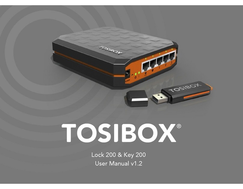
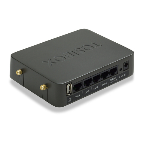
Tosibox Lock 100 User manual

Copyright ©Tosibox Oy 2014
Instrukcja obsługi v2.9

2Table of Contents
Tosibox in brief 3
Tosibox connections - Lock Mode A 4
Tosibox connections - Lock Mode B 5
Tosibox glossary 6
Tosibox products and accessories 7
Key user interface 8
Lock user interface 9
Tosibox Key and Lock serialization 11
Taking the Lock into use - Mode A 13
Taking the Lock into use - Mode B 15
Taking the Key into use 17
Renaming and use of the devices 19
Taking extra Keys into use 21
Remote serialization of extra Keys 23
Creating a Backup Key 25
Connecting Locks 27
Logging in to Lock 28
Software update 30
3G modem for the Lock, Key connection settings for the Lock 31
Industry settings of the Lock 32
Lock Wireless settings 33
Internet connection priorities 34
PUK code for the Key 36
Problem situations 37
Maintenance instructions 38
Tosibox – technical data - Lock 39
Tosibox – technical data - Key 40
Tosibox licences 41
Declaration of Conformity 42
Spis treści
Tosibox w skrócie 3
PołączeniaTosibox – LockTryb A 4
PołączeniaTosibox – LockTryb B 5
Tosibox słownik 6
Tosibox produkty i akcesoria 7
Klucz – interfejs użytkownika 8
Lock – interfejs użytkownika 9
Serializacja Klucza i Lock’aTosibox 11
Pierwsze użycie Lock’a –Tryb A 13
Pierwsze użycie Lock’a –Tryb B 15
Pierwsze użycie Klucza 17
Zmiana nazwy i użycie urządzeń 19
Pierwsze użycie dodatkowych Kluczy 21
Zdalna serializacja dodatkowego Klucza 23
Tworzenie Klucza Zapasowego 25
Podłączanie Lock’ów 27
Logowanie do Lock’a 28
Aktualizacja oprogramowania 30
Modem 3G dla Lock’a, ustawienia połączenia Klucza dla Lock’a 31
Ustawienia przemysłowe Lock’a 32
Ustawienia bezprzewodowe Lock’a 33
Priorytety połączenia Internetowego 34
Kod PUK dla Klucza 36
Sytuacje problemowe 37
Instrukcja obsługi technicznej 38
Tosibox – dane techniczne – Lock 39
Tosibox – dane techniczne – Klucz 40
LicencjeTosibox 41
Deklaracja Zgodności 42

3
Tosibox in brief
Tosibox oers a new, automatic way to establish a remote
connection easily, quickly and securely. Tosibox is a Plug & Go
remote access device. All you need to take it into use is mains
current and an internet connection.The operating principle of
Tosibox resembles that of a mechanical lock and key.
The product consists of a key device (Key) and a locking
device (Lock).The system is brought into use by serializing
the equipment physically through a USB port of the Lock. The
connection to the controlled network devices in the remote
location is opened with a Key that has been serialized to the
Lock.
Tosibox Locks and Keys that have been serialized to each other
will nd each other over internet and from separate local
networks regardless of how they are connected to the internet.
This allows the control of either network devices in the same
local network with the Lock (factory default setting ”Mode A”,
p.12-13) or the network devices directly connected to the Lock
(Lock setting ”Mode B”, p.14-15).
This User Manual is for Lock software version 2.10 and Key
software version 2.10. In case newer software version is used,
download the latest user Manual fromTosibox web site in:
www.tosibox.com/manual
Tosibox w skrócie
Tosibox oferuje nowy automatyczny sposób ustanawiania
łatwych, szybkich i bezpiecznych zdalnych połączeń. Jest
to urządzenie do zdalnego dostępu typu Plug & Go. Do
pracy urządzenia potrzebna jest tylko sieć oraz połączenie
Internetowe. Główna zasada działanieTosibox przypomina
zasadę mechanicznego zamka i klucza.
Produkt składa się urządzenia klucza (Klucz) oraz urządzenia
zamykającego (Lock). System zaczyna działać poprzez
serializację sprzętu zycznie przez port USB Lock’a. Połączenie
do kontrolowanych urządzeń sieciowych w lokalizacjach
zdalnych otwierane jest przez Klucz uprzednio zserializowany
z Lock’iem.
Zserializowane Klucz i Lock połączą się prze Internet z
niezależnych sieci, bez względu na rodzaj połączenia
Internetowego. To pozwala na zarządzanie urządzeniami
sieciowymi zarówno w tej samej sieci lokalnej (domyślne
ustawienie fabryczne„Tryb A”, str. 12-13) lub urządzeniami
sieciowymi podłączonymi bezpośrednio do Lock’a. (ustawienia
Lock’a„Tryb B”, str. 1-15).
Poniższa Instrukcja Obsługi przeznaczona jest do wersji
oprogramowania Lock’a i Klucza 2.10. w przypadku aktualizacji
wersji, najnowszą Instrukcję Obsługi można pobrać z
www.tosibox.com/manual

4
Wejście zasilania DC
Przycisk Reset (nie używany)
Port serwisowy
Port LAN3 (połączenie tylko do
istniejącej sieci LAN)
Nie używany wTrybie A
Port USB (tylko do serializacji)
Modem 3G nie dozwolony w
Trybie A!
LAN3
Serwis
WLAN
Zasilanie
Porty anteny WLAN
LockTryb A

5
Wejście zasilania DC
Przycisk Reset (nie używany)
Port serwisowy
Port LAN3 (połączenie tylko do
istniejącej sieci LAN)
Nie używany wTrybie A
Port USB (tylko do serializacji)
Modem 3G nie dozwolony w
Trybie A!
LAN3
Serwis
WLAN
Zasilanie
LockTryb B
Wejście zasilania DC
Przycisk Reset (nie używany)
Port serwisowy
LAN3 Port
LAN2 Port
LAN1 Port
WAN Port
Port USB (Serializacja
i Modem 3G)
WAN
LAN1
LAN2
LAN3
Serwis
WLAN
Zasilanie
Porty Antenowe WLAN
(Opcja alternatywna to podłączenie do istniejącej

6Tosibox glossary
Key = an intelligent, microprocessor using USB connected key
device that establishes a connection with the locking device.
Sub Key = Accessory Key that has restricted user rights.
Backup Key = a duplicated backup copy of the Key. All serializations
and user rights are automatically synchronized between the original
Key and the Backup Key.
Lock = a locking device that has two dierent modes of operation
(Mode A and Mode B). In Mode A the Lock automatically nds the
network devices in the same local network. In Mode B only the
network devices directly connected to the Lock´s LAN port are
automatically found.The Lock always automatically distributes the
IP-addresses for the Keys and Sub Keys and in Mode B also for the
network devices connected to LAN port of the Lock. The Lock can
also control network devices with xed IP address.
Sub Lock = a Lock that has been converted to Sub Lock mode
of operation.When connecting two Locks with each other one
of them has to be in Sub Lock mode of operation.
Lock Mode A = factory default setting of the Lock. The Lock is
connected to the existing local network via LAN3 -port.
Lock Mode B = Lock mode of operation in which the Lock
enters automatically if an ethernet cable is connected to the
WAN port of the Lock or a 3G modem is connected to the
USB port of the Lock. In Mode B the controlled devices are
connected to LAN1 – LAN3 ports of the Lock (either directly
or via extra switch) or alternatively to the wireless local
network (WLAN)of the Lock.
DHCP-server = Network device or software part of a network
device that distributes IP addresses to the other devices in the same
network
Tosibox słownik
Klucz = inteligentny mikroprocesor korzystający z podłączonego
przez port USB urządzenia klucza, który nawiązuje połączenie z
urządzeniem zamykającym.
Sub-Klucz = Klucz dostępowy z ograniczonymi prawami
użytkownika.
Klucz Zapasowy = zduplikowana kopia zapasowa Klucza.Wszystkie
serializację i prawa użytkownika są automatycznie synchronizow-
ane pomiędzy oryginalnym Kluczem oraz Kluczem Zapasowym.
Lock = urządzenie zamykające, posiadające dwa różne tryby
pracy (Tryb A iTryb B). w Trybie A Lock automatycznie odnajduje
urządzenia sieciowe w tej samej sieci lokalnej.WTrybie B tylko
urządzenia podłączone bezpośrednio do portów sieciowych Lock’a
są automatycznie rozpoznawane. Lock zawsze automatycznie
dystrybuuje adresy IP Kluczy i Sub-Kluczy, a wTrybie B również dla
urządzeń sieciowych podłączonych do portów LAN Lock’a. Lock jest
w stanie również kontrolować urządzenia z ustalonym adresem IP.
Sub-Lock = Lock, który został przekształcony do trybu pracy
Sub-Lock. Przy połączenie dwóch Lock’ów, jeden z nich zostaje
przekształcony do trybu pracy Sub-Lock.
LockTryb A = domyślne ustawienie fabryczne Lock’a. Lock jest
podłączony do istniejącej sieci lokalnej przez port LAN3.
LockTryb B =Tryb pracy Lock’a, w który Lock jest automatycznie
przestawiany, gdy kabel ethernetowy jest podłączony do portu
WAN Lock’a, lub gdy modem 3G jest podłączony do portu USB
Lock’a. wTrybie B kontrolowane urządzenia są podłączone do
portów LAN1 – LAN3 Lock’a (bezpośrednio lub przez dodatkowy
switch), lub alternatywnie do bezprzewodowej sieci lokalnej,
(WLAN) Lock’a.
Serwer DHCP = urządzenie sieciowe lub oprogramowanie
dystrybuujące adresy IP do innych urządzeń tej samej sieci lokalnej.

7
Tosibox products and accessories:
Tosibox Lock Tosibox Key USB Cable
Ethernet Cable AC Adapter Antennas ( 2 )

8Tosibox Key
An intelligent, microprocessor using USB connected key
device that establishes a connection with the locking
device. For more information, please see glossary (page 6).
*Key user interface (installs from the Key). In the
picture on left are TOSIBOX®Lock devices which are
serialized for TOSIBOX® Key and network devices
connected into them. For more options click the
arrow icon button.
Tosibox Klucz
Inteligentny mikroprocesor korzystający z
podłączonego przez port USB urządzenia klucza,
który nawiązuje połączenie z urządzeniem
zamykającym. Więcej informacji w słowniku
(strona 6).
Klucz interfejs użytkownika, (instalowany z Klucza).
Na zdjęciu z lewej strony Lock-i TOSIBOX® które
są zserializowane dla Klucza TOSIBOX®
i podłączone do nich urządzenia sieciowe.
Więcej opcji proszę kliknąć przycisk z ikoną strzałki. Key user interface* / Klucz interfejs użytkownika*

9
Tosibox Lock
A locking device that has two dierent modes
of operation (Mode A and Mode B). For more
information, please see glossary (page 6).
*Web user interface for the Lock.
Changing
the Lock settings via:
• Service port
• Tosibox encrypted VPN connection
• Local network
Tosibox Lock
Urządzenie zamykające posiadające dwa tryby pracy
(Tryb A i Tryb B). Więcej informacji w słowniku (str. 6)
*Webowy interfejs użytkownika dla Lock’a. zmiana
ustawień Lock’a poprzez:
• Port serwisowy
• Szyfrowane połączenie VPN Tosibox
• Sieć lokalną
Web user interface for the Lock* / Webowy interfejs użytkownika dla Lock’a*

10
1. 2.
3.
5.
4.
Serializacja Klucza i Lock’a Tosibox

11
Tosibox Key and Lock serialization
1. Connect theTosibox AC adapter to the Lock and wait
for 2 minutes. Serialize the Key to the Lock by inserting
the Key into the USB port of the Lock. When the LED
on the Key stops blinking, the serialization is complete.
Remove the Key from the Lock.You can also serialize
several Locks to the Key. After the rst Key is serialized
to the Lock, the next Keys (Key or Sub Key) are serialized
with a computer. See section ”Taking extra Keys into
use, p.21”.
2. and 3.Take the Lock into use. Depending on your use
case select the Lock mode of operation Mode A or
mode B. Depending on what is connected to the Lock´s
ethernet ports , the operation mode is determined
automatically. See section ”Taking the Lock into use
-mode A, p.13”or ”Taking the Lock into use -mode B,
p. 14”. Make sure the Lock receives a working internet
connection.
4. Connect the Key to your computer and install the Key.
Follow the section ”Taking the Key into use”.
5. Tosibox connection is ready.You can use, control
and monitor remote objects.
Serializacja Klucza i Lock’a
Tosibox
1. Podłącz zasilacz ACTosiboxa do Lock’a i poczekaj 2
minuty. Zserializuj Klucz do Lock’a wkładając Klucz
do portu USB Lock’a. Kiedy dioda LED na Kluczu
przestanie mrugać, serializacja jest zakończona.Wyjmij
Klucz z Lock’a. Możliwe jest również zserializowanie
kilku Lock’ów do Klucza. Po zserializowaniu
pierwszego Klucza, pozostałe Klucze serializowane
są prze komputer. Zobacz sekcję„Pierwsze użycie
dodatkowych Kluczy”, str. 21
2. i 3. Użycie Lock’a.W zależności od scenariusza wybierz
tryb pracy Lock’a –Tryb A lubTryb B.W zależności od
urządzeń podpiętych do portów ethernetowych Lock’a,
tryb pracy wybierany jest automatycznie. Zobacz sekcję
„Pierwsze użycie Lock’a –Tryb A”, str. 13 lub„Pierwsze
użycie Lock’a –Tryb B”, str. 1. Upewnij się, że Lock jest
podłączony do Internetu
4. Podłącz Klucz do komputera i zainstaluj go. Zobacz
sekcję„Pierwsze użycie Klucza”, str. 17
5. PołączenieTosibox jest gotowe. Możesz używać,
kontrolować oraz monitorować urządzenia

12
LAN
TOSIBOX KEY
COMPUTER 1
COMPUTER 2
PRINTER
LAPTOP !
LAPTOP 2
SERVER
ETHERNET CABLE
TO THE LAN 3 PORT
INTERNET
SERVER
PRINTER
LAPTOP 1
TOSIBOX LOCK
LAPTOP 2
COMPUTER 2
COMPUTER 1
LockTryb A

13
Taking the Lock into use –
Mode A
The Lock has two alternative mode of operation, Mode A
and Mode B.The mode is selected according to what is the
network environment and what is the using purpose of the
Lock. Factory default setting is mode A.
Mode A = Total Plug & Go, factory default setting.Tosibox
Lock is connected to become part of the existing network.
In this case all local network devices with both xed and
dynamic IP-addresses are visible in Lock user interface.
With the Key an access for all these devices can be obtained.
Note: Access to the devices can be limited with separate
MAC-lter functionality (industry setting)
For the Lock only power cord and local network ethernet
cable to Lock´s LAN3 -port is needed. Local network
or Lock settings do not need to be modied. Mode A
requires a DHCP server in the local network. In a functional
local network there is usually always a DHCP server that
distributes IP-addresses to the controlled devices and the
Lock.
Notice: -Do not connect internet to Lock´sWAN Port or a 3G
modem to USB Port. Doing so will automatically switch the
mode of operation to Mode B! From Mode B the Lock does not
automatically return to Mode A.This needs to be done by logging
in to Lock´s user interface with admin user ID (visible in the
bottom of the Lock).
– Do not connect the controlled devices to Lock´s LAN
ports.
– The user of the Key has access to all devices in the local
network. Consider the data security.
– In case access rights need to be restricted, initiate MAC-
ltering (Industry-setting) or use Mode B.
Pierwsze użycie Lock’a –Tryb A
Lock posiada dwa alternatywne tryby pracy –Tryb A i Tryb B.
Tryb pracy wybierany jest zgodnie ze środowiskiem sieciowym
oraz docelowym użyciem Lock’a. Domyślnym ustawieniem
fabrycznym jest Tryb A.
Tryb A = Całkowity Plug & Go, domyślne ustawienie fabryczne.
Tosibox Lock jest podłączony jako część istniejącej sieci.W tym
przypadku wszystkie lokalne urządzenia sieciowe z ustalonymi
jak i dynamicznymi adresami IP są widoczne w interfejsie
użytkownika Lock’a. Dostęp do urządzeń można uzyskać za
pomocą KluczaTosibox.
Uwaga: Dostęp do urządzeń może być ograniczony poprzez
niezależną funkcjonalność ltra MAC (ustawienie przemysłowe).
Dla Lock’a wymagany jest jedynie kabel zasilający oraz kabel
ethernetowy do portu LAN 3 Lock’a. Ustawienia sieci lokalnej
oraz Lock’a nie muszą być zmieniane.Tryb A wymaga serwera
DHCP w sieci lokalnej. W funkcjonalnej sieci lokalnej zwykle
znajduje się serwer DHCP dystrybuujący adresy IP do urządzeń
kontrolowanych oraz Lock’a.
Uwaga: Nie podłączać Internetu do portuWAN Lock’a
lub modemu 3G do portu USB, ponieważ spowoduje to
automatyczne przełączenie wTryb B. Lock nie przełączy się
automatycznie doTrybu A – konieczne jest wtedy zalogowanie
się do interfejsu Lock’a na koncie administratora (widoczne w
dolnej części Lock’a).
– Nie podłączać kontrolowanych urządzeń do portów LAN
Lock’a.
– Użytkownik Klucza ma dostęp do wszystkich urządzeń w
sieci lokalnej. Proszę wziąć pod uwagę temat bezpieczeństwa
danych.
– W przypadku konieczności ograniczenia praw dostępu, należy
użyć ltrowanie MAC (ustawienia fabryczne interfejsu Lock’a /
industrial settings) lub przejść do Trybu B.

14
LAN
TOSIBOX KEY
COMPUTER 2
LAPTOP 2
SERVER INTERNET
SERVER
PRINTER
LAPTOP 1
LAPTOP 2
COMPUTER 2
COMPUTER 1
INTERNET CONNECTION
TO THE WAN PORT OR
3G MODEM
TO THE USB PORT
TOSIBOX LOCK
Taking the Lock into use –
Mode B
Mode B = Mode of operation that the Lock switches into
from Mode A, whenWAN-Port of the Lock is connected
with an internet or a 3G modem is connected into the
USB port of the Lock. In Mode B the Lock creates its own
protected local network from the connected devices. Only
these devices, connected to the Lock directly by cable or
wirelessly, are accessible with the Key
Note:
– Follow the section ”3G modem for the Lock”instructions
when connecting the 3G modem into the Lock´s USB
port.
– Mode B can be switched back to Mode A only with
admin user-ID from the Lock´s user interface.
– In case a Lock which is in mode B is connected from
Lock´s LAN port (LAN1, LAN2 or LAN3) to another local
network that has a working DHCP server, Lock´s own
LAN is disactivated. It is reactivated after the improper
connection is removed.
Taking into use the controlled devices with dynamic IP addresses:
In case all the controlled devices have dynamic IP addresses,
they will automatically connect to the Lock. In this case the LAN-
network is created in Plug & Go principle.
Taking into use the controlled devices with static IP addresses:
Note! When the Lock is in ”Mode A”and when there is a
DHCP service in the network, the Lock will automatically
nd also devices with xed IP address in the same network.
In other case:
1. Connect the computer into Lock´s Service Port. Type
“http://service.tosibox”or“172.17.17.17”into the web browser.
The user ID is ”admin”and the password is visible inthe bottom
of the Lock.
2. Go to Network > LAN and see the IP address of the Lock
from ”Ipv4 address”. Check also that the network mask in
”Ipv4 netmask”is set to 255.255.255.192.
3. Go to the settings of the controlled device. Set the device
into the same IP-address space than the Lock.
LockTryb B

15
The fourth number of the IP address of the controlled
device shall be 1-9 upwards from the Lock´s IP addresses
fourth number. Set the network mask 255.255.255.192.
An example: Lock´s LAN address is 10.25.15.193.
In this case the rst controlled device´s IP address is
10.25.15.194.The next shall be 10.25.15.195 and so on.
4. Go to Lock settings. Set the controlled device´s IP
address (eg. 10.25.15.194) into Lock´s user interface with
”new network device”option. If needed, the device can
be renamed.You can also use ”Scan for LAN devices”
option to make the Lock immediately and automatically
nd the devices in the same network address space
Pierwsze użycie kontrolowanych urządzeń z dynamicznym
adresem IP:
W przypadku, gdy wszystkie kontrolowane urządzenia posiadają
dynamiczne adresy IP, zostaną automatycznie podłączone do
Lock’a.Tak utworzona sieć LAN działa w trybie Plug & Go.
Pierwsze użycie kontrolowanych urządzeń ze statycznym
adresem IP:
Uwaga! Kiedy Lock pracuje wTrybie A, i serwer DHCP jest obecny
w sieci, Lock automatycznie znajdzie urządzenia ze statycznym
adresem IP. W innym przypadku:
1. Podłącz komputer do portu serwisowego Lock’a. W
przeglądarce wpisz“http://service.tosibox”lub“172.17.17.17”.
Podaj„Admin”jako ID, a hasło jest widoczne w dolnej części
Lock’a.
2. Przejdź do Sieć > LAN i sprawdź adres IP Lock’a z„IPv4 adres”.
Sprawdź również, czy maska sieci w„IPv4 netmask”jest
ustawiona na 255.255.255.192.
3. Przejdź do ustawień kontrolowanego urządzenia. Ustaw
urządzenie na ten sam zakres adresów IP, w jakim znajduje się
Lock.
Czwarty numer adresu IP kontrolowanego urządzenia
powinien być pomiędzy 1 i 9 w górę od czwartego numeru
adresu IP Lock’a. Maska sieci powinna być ustawiona na
255.255.255.192.
Przykład: adres LAN Lock’a to 10.25.15.193. W tym przypadku
adres IP pierwszego kontrolowanego urządzenia to
10.25.15.194. Następne urządzenie to 10.25.15.195, itd.
4. Przejdź do ustawień Lock’a. Ustaw adres IP kontrolowanego
urządzenia (np. 10.25.15.194) w interfejsie Lock’a przy opcji
„New Network Device”.W razie potrzeby można zmienić nazwę
urządzenia. Możliwe jest również użycie opcji„Scan for LAN
devices”aby Lock automatycznie wyszukał urządzenia w tym
samym zakresie adresów IP.
Pierwsze użycie Lock’a –Tryb B
Tryb B = tryb pracy, w który Lock przechodzi zTrybu A kiedy do
portu WAN Lock’a podłączony jest Internet, lub gdy modem 3G
jest podłączony do portu USB Lock’a.W Trybie B Lock tworzy
własną chronioną sieć lokalną z połączonych urządzeń.Tylko te
urządzenia, które są podłączone do Lock’a bezpośrednio kablem
lub bezprzewodowo, są dostępne przy użyciu Klucza.
Uwaga:
–Przejdź do sekcji„Modem 3G dla Lock’a”po instrukcję
podłączenia modemu 3G do portu USB Lock’a.
– Lock może przejść wTryb A z Trybu B tylko na numerze ID
administratora, poprzez interfejs Lock’a.
– W przypadku, gdy Lock będący wTrybie B jest połączony
z portu LAN (LAN1, LAN2 lub LAN3) do innej sieci lokalnej
z serwerem DHCP, sieć własna Lock’a jest dezaktywowana.
Sieć będzie przywrócona po usunięciu nieprawidłowego
połączenia.

16
1. Pierwsze użycie klucza.
2. Ustaw hasło.
3. Interfejs użytkownika Klucza

17
Taking the Key into use
1. Insert the serialized Key into the USB -port of your computer.
Start“Setup_Tosibox”executable from the“Autoplay window
that opens on the desktop. If your computer asks whether you
allow tosibox to make changes, click allow. Key setup starts.
After the setup close the setup window by choosing ”close”.
2. The Key will ask for a password which you can enter, if
you wish (recommended). By entering a password, you
can prevent the unauthorized use of the Key. Store the
password safely.
3. Key opens up a window that shows the Locks that have
been serialized to the Key. Connect the Key with the
wanted Lock by clicking the“Connect”icon of this Lock.
4. Key info dialogue shows the status of the connection
establishment between the Key and the Lock.
Taking the Key into use is ready.
The Lock symbol is shown with dierent colour according
to the operating status of the Lock:
– Red = Lock is not connected to the internet
– Yellow = Lock and Key have detected each other but
the connection with the Lock and Key has not yet been
established
– Green = Encrypted connection between Key and Lock is
ready
The Key symbol in the task bar of the computer is shown
withdifferentcolouraccordingtothe operatingstatus oftheKey:
– Red = Key has not reached a connection to the internet
– Yellow = Key has access to internet and found at least one
Lock but none of the Locks are yet connected to the Key
– Green = Key has made an encrypted connection to at least
one Lock
Pierwsze użycie Klucza
1. Włóż zserializowany Klucz do portu USB komputera. Uruchom
aplikację„Setup_Tosibox”z menu„Autoplay”otwartego na
pulpicie. Jeśli komputer zapyta o zgodę na dokonanie zmian,
kliknij„Zezwól”. Uruchomi się program instalacyjny Klucza. Po
zakończonej instalacji zamknij okno instalatora klikając„Close”.
2. Klucz zapyta o hasło (opcjonalne, choć rekomendowane).
Ustalenie hasło zapobiegnie nieautoryzowanemu użyciu Klucza.
3. Pojawi się okno pokazujące Lock’i zserializowane do Klucza.
Połącz Klucz z żądanym Lock’iem klikając w ikonę„Connect”na
Lock’u.
4. Okno dialogowe Klucza pokaże stan połączenia pomiędzy
Kluczem a Lock’iem.
Konguracja Klucza została zakończona.
Symbol Lock’a wyświetla różne kolory w zależności od stanu pracy
Lock’a:
– Czerwony = Lock nie podłączony do Internetu
– Żółty = Lock i Klucz wyszukały się, ale połączenie między nimi
nie zostało jeszcze nawiązane.
– Zielony = Szyfrowane połączenie pomiędzy Kluczem i Lock’iem
jest gotowe.
Symbol Klucza wyświetla różne kolory w zależności od stanu pracy
Klucza:
– Czerwony = Klucz nie podłączony do Internetu
– Żółty = Klucz ma połączenie z Internetem, i znalazł przynajmniej
jeden Lock, ale żaden Lock nie jest jeszcze połączony z Kluczem.
– Zielony = Klucz nawiązał szyfrowane połączenie z przynajmniej
jednym Lock’iem.

18 Interfejs użytkownika Klucza
Zdjęcie 1 Zdjęcie 2
Zdjęcie 3

19
Zmiana nazwy i użycie urządzeń.
Zdjęcie 1.
Widok startowy interfejsu Klucza. Po dwukrotnym
kliknięciu na ikonę Lock’a, interfejs Lock’a otwierany jest w
domyślnej przeglądarce.
Zdjęcie 2.
Klikając ikonę :…”otwiera się dodatkowe menu.
1. W interfejsie Klucza można ustawić, aby interfejs
otwierał się automatycznie w domyślnej przeglądarce,
ustawiając„Open browser automatically when con-
nected”
2. Obejrzyj szczegóły urządzeń w“Show all details”
3. Zmień nazwę Lock’a klikając w„Rename device”.Ta
nazwa widoczna jest tylko dla Klucza.
Zdjęcie 3.
1. Można uruchomić przeglądarkowy interfejs
użytkownika kontrolowanego urządzenia poprzez
„Open with browser (http)”.
2. Można połączyć serwer do współdzielenia sieci poprzez
„Open windows network share”.
3. Można otworzyć zdalne połączenie poprzez„Open
Remote Desktop Connection (RDP), if available”.
4. Można sprawdzić funkcjonalność kontrolowanego
urządzenia komendą PING poprzez„Check if host avail-
able (PING)”.
Renaming and use of the devices
Picture 1.
Start view of Key user interface. By double clicking
the Lock icon, the Lock user interface opens in the
default browser.
Picture 2.
By clicking the arrow icon, an extra menu opens.
1. In Key user interface you can choose the Lock user
interface to open automatically in default browser
in“Open browser automatically when connected”
2. See details of the devices in“Show all details”.
3. Rename the Lock by clicking“Rename device”.
Please note that this name is visible only for this
Key.
Picture 3.
1. You can open the browser user interface of the
controlled device in“Open with browser (http)”
2. You can connect the server to network sharing in
“Open windows network share”
3. You can open the remote desktop connection in
“Open Remote Desktop Connection (RDP), if avail-
able”
4. You can check the functionality of the controlled
device with PING command in“Check if host avail-
able (PING)”

20
Taking extra Keys into use / Pierwsze użycie dodatkowych Kluczy
Zdjęcie 1 Zdjęcie 2
Zdjęcie 3 Zdjęcie 4
Other manuals for Lock 100
6
Table of contents
Other Tosibox Wireless Access Point manuals
Popular Wireless Access Point manuals by other brands

P2 MOBILE TECHNOLOGIES LIMITED
P2 MOBILE TECHNOLOGIES LIMITED Z100 manual
ZComax
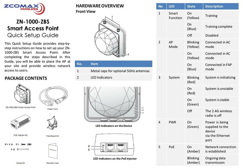
ZComax ZN-1000-ZBS Quick setup guide
IPmitter
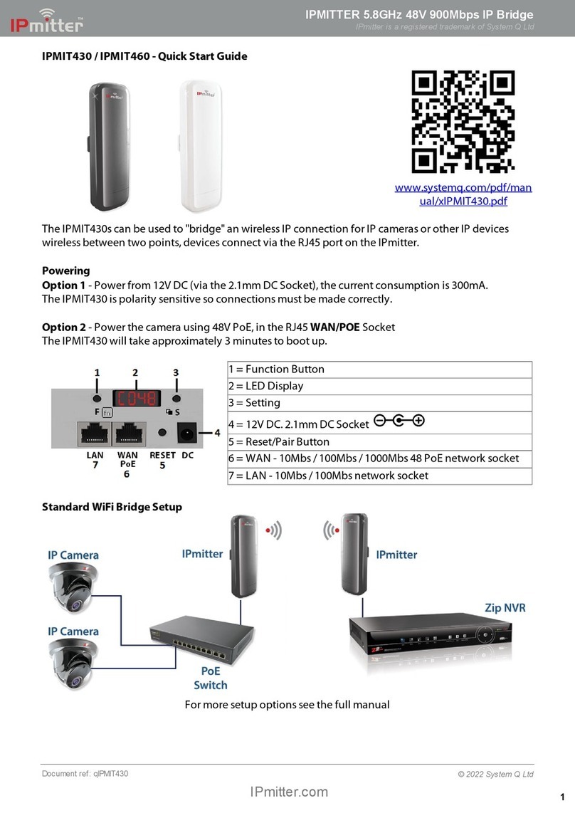
IPmitter IPMIT430 quick start guide

Meru Networks
Meru Networks AP433e installation guide
OTC Wireless
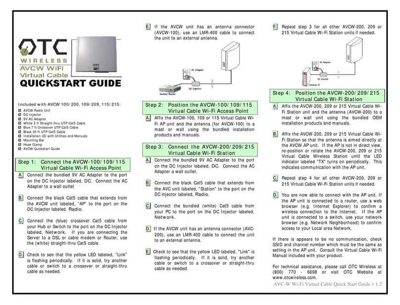
OTC Wireless AVCW 100 quick start guide
Draytek
Draytek VigorAP 910C quick start guide
