TOSO CREATY CORD TWIN KIT User manual

TOSO
ROMAN SHADE
CREATY CORD TWIN KIT
NO.S – 07091406
Instruction Manual
Thank you for purchasing TOSO products. To ensure safe use of this product,
please read this manual carefully before use.
■Caution …………………………………………………………………..2
■Product View and Part Names…………………………………………4
■Style ………………………………………………………………………6
■Assembling……………………………………………………………….6
■Installation and Detaching……………………………………………..12
■How to Operate…………………………………………………………14
■Cleaning…………………………………………………………………15
■Adjustment Method for Leveling Top Right and Left of Screen……17
■Disposal of Packing Materials………………………………………...17
This manual contains information for a user to safely operate this product.
Please provide this manual to a customer.
Guide for Distributors and Installation Contractors
Index
-1-

*This manual contains cautions and instructions for safe use of the product.
Please read it carefully before use and ensure appropriate use.
●This document illustrates the dangers of using this product without taking
necessary precautions. Please refer to below symbols for different types of
safety points.
●This document illustrates safety points to be kept using below symbols.
■
Precautions upon installing the product (Please read before installation.)
■Safety in Use (Please read thoroughly)
ATTENTION
When there is strong wind,
please either close the
window or have the screen
completel
y
opened up.
Please do not dismantle
the mechanical assembly
nor lubricate the moving
parts of this product. This
will ensure physical
damage or malfunction of
the product.
Please do not use it
around open flames.
Please remember to always
use the cord or wand when
handling this product. Please
do not attempt to handle the
screen directl
y
.
A
round the area where the
screen is to open and close,
please remember to clear all
objects which may break
when placed around the
screen.
CAUTION
illustrates when misused, there are dangers of serious
injuries or possible fatal accidents.
CAUTION
illustrates when misused, there are dangers of casualties or
possible physical damage of the product.
ATTENTION
Illustrates specific conducts which are prohibited.
Illustrates specific guidelines which are enforced.
Illustrates specific conducts which are prohibited.
Screws provided are for xylem only. Do not use on materials other than
xylem.
Check the foundation base and strength of the material before
installing this product. If not installed properly to the foundation base,
there are dangers of it falling.
Install a product as instructed with necessary quantity of brackets. If
not the product may fall.
CAUTION
This product is intended for indoor use. Please do not use
it for exterior purpose.
Locations subject to high temperatures and high humidity,
or areas where water may leak, should be avoided.
Make sure to install a product horizontally.
ATTENTION
Please avoid conduct which may result in the
cord or the chain entangling the body or hooked
onto something. This may cause accident..
CAUTION
Please do not treat the
product with rapid or drastic
motion. This may damage
the product or cause for it
fall down.
JAPAN Blind Industrial Association
Please do not hang nor
dangle from this product. This
may damage the product or
cause for it fall down.
ATTENTION
When there is strong wind,
please either close the
window or have the screen
completel
y
opened up.
Please do not dismantle
the mechanical assembly
nor lubricate the moving
parts of this product. This
will ensure physical
damage or malfunction of
the product.
Please do not use it
around open flames.
Please remember to always
use the cord or wand when
handling this product. Please
do not attempt to handle the
screen directl
y
.
A
round the area where the
screen is to open and close,
please remember to clear all
objects which may break
when placed around the
screen.
-2- -3-
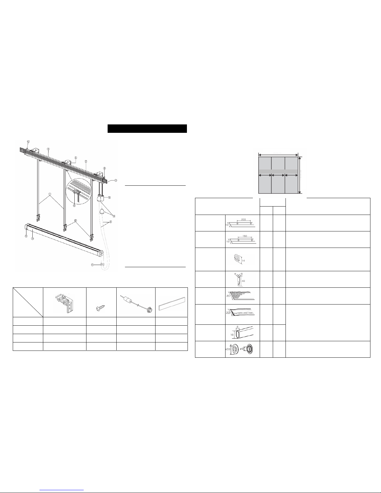
■Number of Components
Bracket
(Universal Bracket)
Bracket
Fixing Screw
(∅3.5×20)
Operation Cord Weight Flat
Bar
900 2 pieces 2 pieces 1 set 450mm 1pc
1400 3 pieces 3 pieces 1 set -
1900 3 pieces 3 pieces 1 set -
2400 4 pieces 4 pieces 1 set -
■Product Weight 2.3kg (Plain Style + Plain Style: Width2,000mm × Height 2,000mm)
*Weight of screen is not included.
■Parts for Sewing (sold separately)
▪In addition too the kit, necessary sewing parts are available for purchase.
See the table below and decide what you need to buy.
Style
Part Name (mm)
Plain
Sharp
Sample quantity to be used
Looped Tape
200 ○ - (Product height + 100) mm × (Number of swags + 1) pcs.
Looped Tape ○ - (Product height + 100) mm × (Number of swags + 1) pcs.
Ring for Tape ○ -
To be attached to “Loop Tape”
●In the case of Looped Tape 200,
(Product height ÷ 200mm) pcs. × (Number of swags + 1)pcs.
●In the case of Looped Tape,
(Product height ÷ 150mm) pcs. × (Number of swags + 1)pcs.
Cord Adjuster
○ ○ (Number of swags + 1) pcs.
Velcro Tape
For Screen
(female side) ○ ○ (Product width) mm
Shaper Tape
2
White, beige, brown, gray
- ○
Shaper 10 - ○
●In the case of a product height up to 1,500mm,
(120-mm pitch in the direction of product height) pcs.
×
(product width mm) pcs.
●In the case of product height of 1,510 to 3,000mm,
(150-mm pitch in the direction of product height) pcs.
×
(product width mm) pcs.
Twin Ring ○ ○ (Number of swags + 1) pcs.
Product View and Part Names
Part Names
①Head Rail
②Slide-in Velcro Tape
③Bracket
④Stopper Case
(Stopper Main Body)
⑤Cord Guide
(Cord Guide A/B)
⑥Cap
⑦Lift Cord
⑧Cord Stop
⑨Operation Cord
⑩Cord Separator
⑪Safety Joint
⑫Cord Adjuster
⑬Return (Option)
⑭Weight Bar
Components
Product
Width
(
mm
)
Product Width
Swa
g
Swa
g
Swa
g
Product Heigh
t
-4- -5-
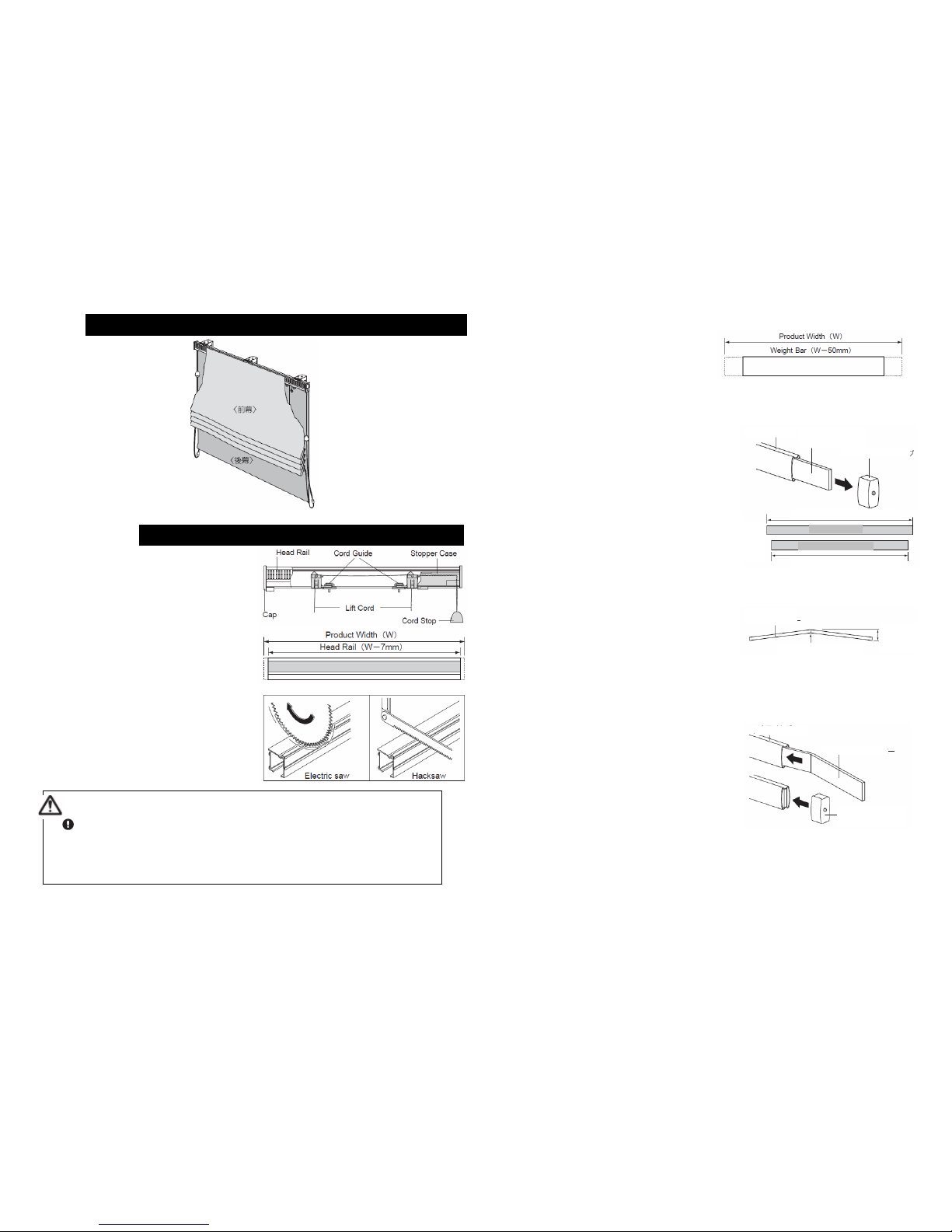
■Flat Window
●In the case of operation
on both sides
* The parts come preassembled as shown at right.
* To change the product to the left-hand operation
type, assemble the stopper case on the
left-hand side, the cap of the right-hand side,
and the cord guide with its right and left
reversed, as viewed facing the product.
1 Remove the stopper case, cord guide, cap,
and slide-in Velcro tape from the head rail,
and cut the head rail to the necessary size.
(Determine the cutting size by referring to the
illustration at right.)
* After removing the parts, use caution not to
allow the lift cord to come out the stopper and
stopper case.
* When cutting the head rail, be sure to remove
the slide-in Velcro tape in advance from the rail.
2 Cut the weight bar to the necessary size.
(Determine the cutting size by referring to the
illustration at right.)
<In the case of a kit with a product width of 900 mm>
*To allow lowering the screen completely to the
bottom, kits with a product width of 900 mm
come with weight flat bars inserted. Follow the
procedure below to cut the weight bar.
1) Remove the weight bar cap from the weight
bar and draw out the weight flat bars.
2) Cut the weight bar and weight flat bars of
the rear screen as illustrated at right.
3) Bend the center of the weight flat bars by
hand (by approximately 20 to 30 mm),
insert them into the weight bar, then attach
the weight bar cap.
*The weight flat bars are bent, such that they
can be retained inside the weight bar.
*After you have completed assembly, make sure
to check if the fabric comes down to its
lowermost position.
Style
Assembling
Cut the head rail before assembling the stopper case, stopper, and cord
guide. After cutting the rail, completely remove any loose cutting chips from
the inside of the head rail. The presence of cutting chips in the stopper
case, stopper, or cord guide might prevent the product from functioning
normally.
ATTENTION
Wei
g
ht Ba
r
Wei
g
ht Bar Cap
Wei
g
ht Flat Ba
r
Wei
g
ht Ba
r
Wei
g
ht Flat Ba
r
Wei
g
ht Bar Cap
Weight Flat
Ba
r
Approx
20-30 mm
Bend in the cente
r
Product Width
(
W
)
–
72 mm
Product Width
(
W
)
–
70 mm
Weight Bar
Weight Flat Bar
〈
Rea
r
Screen〉
-6- -7-

3 Install the stopper case on the head rail.
* Accommodate the front screen lift cords inside
the head rail. However, leave the rear screen lift
cords exposed in front of the head rail.
* Be careful not to let the lift cords become
caught in the stopper case.
4 Separate the cord guide into two parts: cord
guide A and cord guide B.
5 With the head rail groove in the up position,
insert cord guide A into the groove while
twisting the cord by 45 degrees.
* Install cord guide A with the △mark directed
toward the stopper case.
6 Pass the front screen lift cord through cord
guide A.
* Pass the front screen lift cords through cord
guide A on the stopper-case side sequentially
from the one on the rear.
* Pass the front screen lift cord through the
outside of the metal pin of cord guide A.
7 Place the rear screen lift cord on cord guide A.
8 Direct the knob of cord guide B toward the
stopper case side and fasten it to cord guide
A.
* Pass the rear screen lift cords through cord
guide B on the stopper-case side sequentially
from the one on the front side.
* Pass the front screen lift cord and rear screen
lift cord through the outside of the metal pin.
9 Only the cord guide B adjacent to the stopper
case, direct the knob toward the cap side and
remove the lift cord from between the knob
and the metal pin. After removing the Lift
cord, attach it to the cord guide.
10 Insert the cap into the head rail.
11 Install the fabric (optional purchase) on the
head rail.
* Attach the fabric by following the method
described for each style.
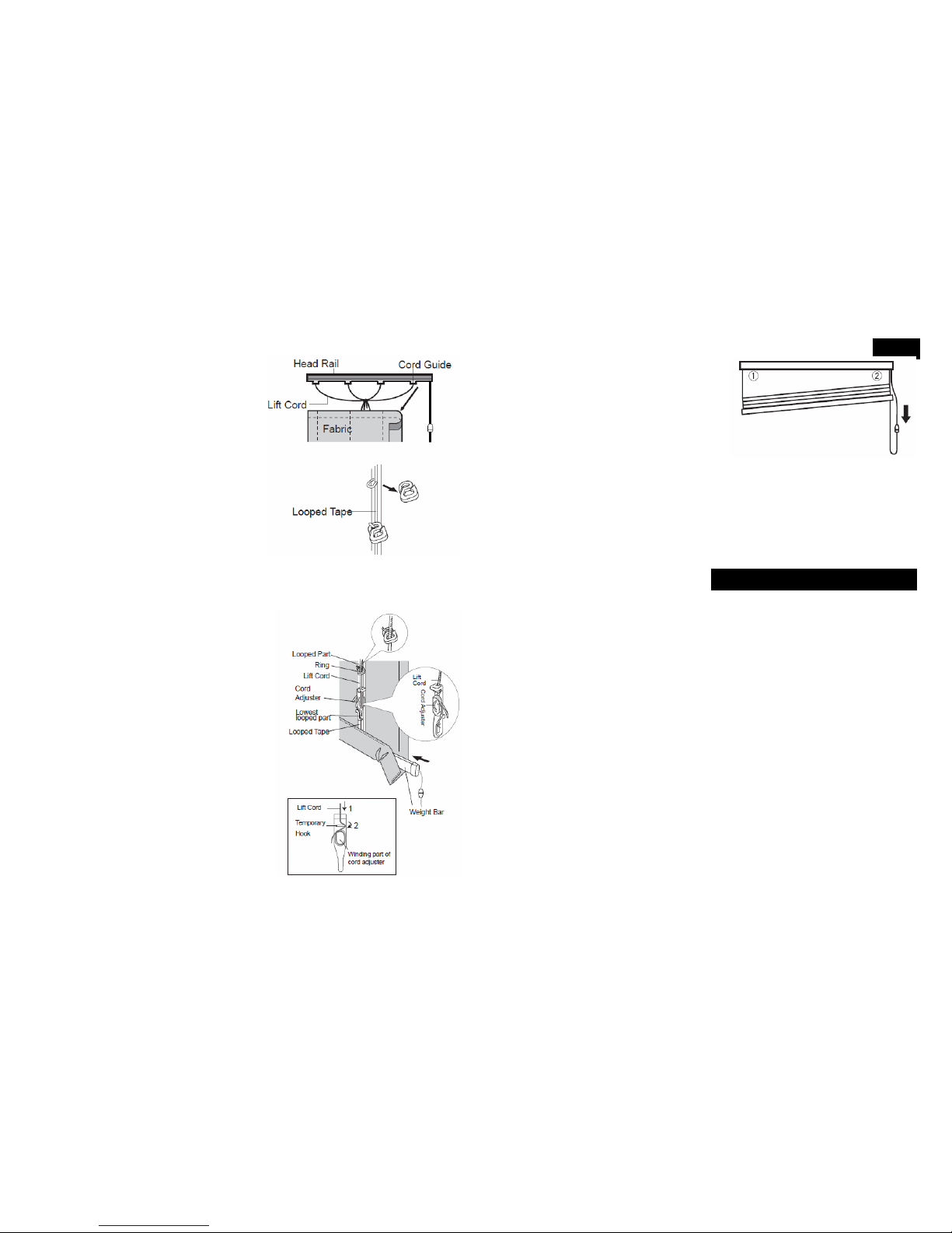
■How to Install the Front Screen
1 Install the fabric (optional purchase) on the
head rail.
2 Align the cord guide to the position of the
looped tape and fasten.
(1) Slide cord guide B, fasten to cord guide A, to
the looped tape.
(2) Twist the knob of the cord guide again by 90
degrees and fasten it in place.
3 Tack the lift cords with clothespins or other
clips such that the cord stop will be positioned
approximately 15 cm from the top of the head
rail (or in a position at which the cord can be
gripped easily for operation). (Remove the
temporary tacking when operating the
screen.)
* Trim the lift cords leaving a length equivalent
to the product height + approx. 10cm.
When fastening the stopper case, tighten the fixing screw just enough to
leave the stopper fastened securely. Excessive tightening of the screw
might prevent the product from functioning normally.
ATTENTION
Stopper CaseHead Rail
Lift Cord
Lift Cord
Sto
pp
er Case
Lift Cord
Lift Cord Metal Pin
Cord Guide A
Cord Guide B Stopper Case
Lift Cord
Lift Cord
Head Rail
Front Screen
(Option)
Head Rail
Approx 15cm
Cord Stop
Approx 10cm
Product
Width
Clothes pin or other clip
Cap Cord Guide A Stopper Case
Cord Guide B
Metal pin
Lift Cord for
Front Screen Lift Cord for
Rear Screen
-8- -9-

4 Hook the smaller hole of the ring onto the
looped part of the looped tape.
5 Attach the cord adjuster to the lowest looped
part of the looped tape.
* If the ring cannot be detached, attach the cord
adjuster directly to the ring.
6 Pass the lift cord through the large hole of the
ring, starting from the top of the fabric. If you
happen to omit a ring, the lift cord can be
inserted through the notch in the rings.
7 Pass the lift cord through the top of the cord
adjuster (1) and align the fastened position to
the top of the cord adjuster. The cord can be
fastened temporarily by hanging it on the
temporary hook and swinging the cord to the
opposite side (2). While adjusting the
balance between the right and left top edges
of the fabric, wind the lift cord around the cord
adjuster, ensuring that the tensions in the lift
cords remain roughly equal. (At this time,
trim the surplus of the cords.)
8 After passing the operation cord (safety joint
side) through the weight bar cap, tie the end
part to fasten it to the weight bar.
9 Insert the weight bar into the fabric.
10 Adjust the length of the operation cord such
that the safety joint will be situated in the
position shown at right (approximately 10 cm
below the lowest point of the operation cord.)
Then attach the lower part of cord stop to the
upper part.
■How to Install the Rear Screen
1 Install the fabric (optional purchase) on the
head rail.
2 Pass the lift cord (for the rear screen) through
the rear screen ring and take it out to the rear.
3 For attaching the weight bar and cords to the
screen, see “How to Install the Front Screen”
on page 9 (3) to page 10 (9).”
Head Rail
Fabric (option)
Ring
Front
Screen
Rear
Screen
Lift Cord
-10- -11-

■Installation Type
■Installation Diagram (mm)
* In the case of a bay window, only the ceiling attachment is available.
* Place the fixing screw in either of the position shown above, according to the condition of the
underlying backing material.
* Fasten the front attachment of a product exceeding 2,010 mm in width through the upper screw
hole in the bracket.
■Position of Bracket
●Install the brackets on both sides
approximately 10 cm from both ends of the
head rail using fixing screws (pan-head, ∅3.5 ×
20).
Product Width (mm) Number of Bracket
~ 1200 2 pcs.
~ 2000 3 pcs.
~ 2400 4 pcs.
* In the case of a product of 1,210 mm or more
in width, three or more brackets will be required.
Install them at even intervals.
■How to attach and detach a head rail
〈Attaching〉
1 Hook a head rail on temporal hook of bracket.
2 Push main body into the bracket until it firmly
fixed.
〈Detaching〉
1 Pull out a head rail while pressing release
button of bracket.
2 Take main body off from temporal hook of
bracket.
Installation and Detaching
The attached screw for installing the bracket is for xylem section. Please do
not use other than xylem section.
ATTENTION
〈
C
e
ili
ng
A
ttac
h
ment
〉
〈
F
ront
A
tt
a
〈
F
ront
A
Fixing Scre
w
Fixing Scre
w
〈
F
ront
A
ttac
h
ment
〉
〈
F
ront
A
Fixing Scre
w
After installing the brackets, check
to ensure that they are fastened
securely to the main body.
CAUTION
-12- -13-
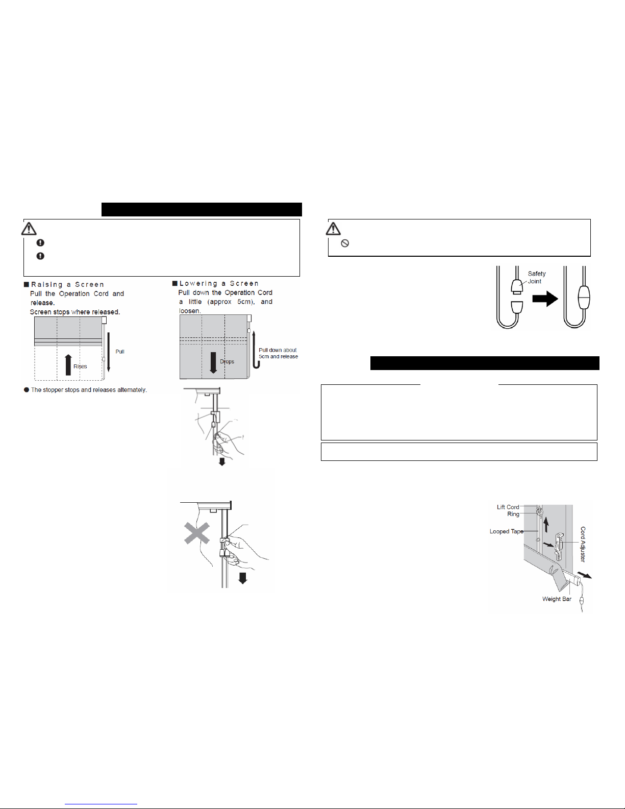
* To operate the screen, hold the cord
stopper or operation cord and pull it
directly downward.
■Safety Joint
●The safety joint is intended to release the
operation cord to avoid danger in the event that the
cord becomes caught around the child’s neck or
body.
●The safety joint will come apart if force is applied
to the cord or if the cord is held near the joint in
operation. If the safety joint comes apart for any
reason, do not leave it in this condition, but instead
of make sure to reconnect it before using the
screen.
■Removing Fabric
* Before removing the lift cord from the cord adjuster, place a mark on the cord (at the
top end of the cord adjuster) using a pen. The mark will serve as a guide when
winding up the cord later, allowing for easy reinstallation. Be very careful not to stain
the fabric with the pen.
1 Lower the fabric fully.
2 Unwind the lift cord from the cord adjuster
at the bottom and remove the cord
adjuster from the looped tape.
* Keep the cord adjuster in a safe place to
avoid loosing it.
How to Operate
Be sure to raise and lower the screen using the operation cord.
When lowering the screen, make sure to hold the cord by hand. If you
release your hand from the cord, the screen may drop abruptly, posing a
danger.
ATTENTION
Do not allow children to play with the operation cords. An accident may
occur in the event the cord is caught around the child’s neck or body.
WARNING
Cleaning
●Check the label for handling instructions affixed to the back of the fabric.
●I the fabric comes with a label of pictorial washing instructions, follow the
instructions provided on the label
●If the fabric comes with a label indicating method for care, follow the instructions
provided on the label.
Care of the fabric
* After removing the fabric from the head rail, be sure to bundle and tie the cords
to ensure that the
y
will not fall out of the cord
g
uides.
Lift Cord
(Front Screen)
Lift Cord
(Rear Screen)
Cord Stop
(Front Screen)
Cord Stop
(Rear Screen)
Operation Cord
Cord Separator
Cord Separator
Do not operate holding cord separator
in order to operate normally.
-14- -15-
3 Remove the weight bar from the fabric.
4 Detach fabric from the head rail.
5 Tie the lift cords together so that they
won’t come off from the cord guides.
6 Remove the rings from the looped tape.
* Keep the rings in a safe place to avoid
losing them.
■How to Install Screens
* Follow the same procedure for both the front
screen and the rear screen.
1 Install the fabric on the head rail.
2 Hook the smaller hole of the ring onto the
looped part of the looped tape
3 Attach the cord adjuster to the lowest looped
part of the looped tape.
4 Insert the weight bar into the fabric.
5 Pass the lift cord through the large hole of the
ring, starting from the top of the fabric. If you
happen to omit a ring, the lift cord can be
inserted through the notch in the rings.
6 Pass the lift cord through the top of the cord
adjuster (1) and align the fastened position to
the top of the cord adjuster. The cord can be
fastened temporarily by hanging it on the
temporary hook and swinging the cord to the
opposite side (2). While adjusting the
balance between the right and left top edges
of the fabric, wind the lift cord around the cord
adjuster, ensuring that the tensions in the lift
cords remain roughly equal. (At this time,
trim the surplus of the cords.)
*Determine the location where the lift cord is to be wound by using the position that originally
came with the cord wound or marked with a pen as the guide. Note that pulling the cord out
forcibly might prevent normal operation.
1 After installing the fabric, raise it to check to
see if its right and left top edges are equal.
2 If the heights are not equal, bring down the
fabric and adjust the heights using procedure
described below, such that the tensions of the
lift cords remain equal.
(1) Redo the winding of the lift cord that is
wrapped around the cord adjuster of the
lowered side to make it somewhat
shorter.
(2) Redo the winding of the lift cord that is
wrapped around the cord adjuster of the
raised side to make it some what longer.
●Dispose of the packing materials after separating burnable and non-burnable
materials.
●Follow local waste management law..
Adjustm
e
nt Method for Leveling Top Right and Left of Scree
n
Disposal of Packing Materials
-16- -17-
Table of contents


