manuals.online logo
Brands
  1. Home
  2. •
  3. Brands
  4. •
  5. Total Protection Solutions
  6. •
  7. Surge Protector
  8. •
  9. Total Protection Solutions ComTrack TK-CT2-190TLP4-RJ-T1/E1-C User manual

Total Protection Solutions ComTrack TK-CT2-190TLP4-RJ-T1/E1-C User manual

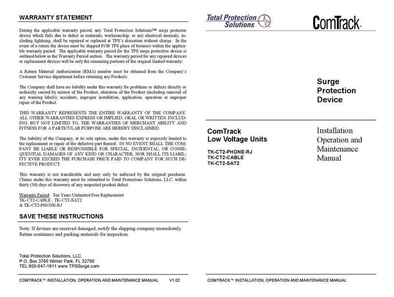
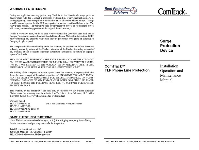
WARRANTY STATEMENT
During the applicable warranty period, any Total Protection Solutions™ surge protector
device which fails due to defect in materials, workmanship, or any electrical anomaly, in-
cluding lightning, shall be repaired or replaced at TPS’s discretion without charge. The ap-
plicable warranty period for the TPS surge protective device is outlined below in the War-
ranty Period section. The warranty period for any repaired devices or replacement devices
will be only the remaining portions of the original limited warranty.
Within a reasonable time, but in no case to exceed forty-five (45) days, user shall contact
Company's customer service department and obtain a Return Material Authorization (RMA)
before returning any products. User shall ship the product(s), with proof of purchase, to
Company freight prepaid.
The Company shall have no liability under this warranty for problems or defects directly or
indirectly caused by misuse of the Product, alteration of the Product (including removal of
any warning labels), accidents, improper installation, application, operation or improper
repair of the Product.
THIS WARRANTY REPRESENTS THE ENTIRE WARRANTY OF THE COMPANY.
ALL OTHER WARRANTIES EXPRESS OR IMPLIED, ORAL OR WRITTEN, INCLUD-
ING, BUT NOT LIMITED TO, THE WARRANTIES OF MERCHANT ABILITY AND
FITNESS FOR A PARTICULAR PURPOSE ARE HEREBY DISCLAIMED.
The liability of the Company, at its sole option, under this warranty is expressly limited to
the replacement or repair of the defective part thereof. IN NO EVENT SHALL THE COM-
PANY BE LIABLE OR RESPONSIBLE FOR SPECIAL, INCIDENTAL, OR CONSE-
QUENTIAL DAMAGES OF ANY KIND OR CHARACTER, NOR SHALL ITS LIABIL-
ITY EVER EXCEED THE PURCHASE PRICE PAID TO COMPANY FOR SUCH DE-
FECTIVE PRODUCT.
This warranty is not transferable and may only be enforced by the original purchaser.
Claims under this warranty must be submitted to Total Protections Solutions, LLC. within
thirty (30) days of discovery of any suspected product defect.
Warranty Period
TK-CT2-190TLP1-TB Ten Years Unlimited Free Replacement
TK-CT2-190TLP2-TB
TK-CT2-190TLP4-RJ-T1/E1-C
TK-CT2-190TLP4-TB, TK-CT2-190TLP5-TB
SAVE THESE INSTRUCTIONS
Note: If devices are received damaged, notify the shipping company immediately.
Retain containers and packing materials for inspection.
ComTrack™
TLP Phone Line Protection
COMTRACK™ INSTALLATION, OPERATION AND MAINTENANCE MANUAL V1.02 COMTRACK™ INSTALLATION, OPERATION AND MAINTENANCE MANUAL
C
om
T
rack
™
Surge
Protection
Device
Installation
Operation and
Maintenance
Manual
Total Protection Solutions, LLC.
P.O. Box 3760, Winter Park, FL 32790
TEL: 800-647-1911 www.TPSSurge.com
Page: 2
1. Never install telephone wiring during a lightning storm.
2. This product is for INDOOR USE ONLY.
3. TLP Series suppressors are intended for use on the equipment side of UL 497 listed
Primary Protectors.
4. Read and understand all instructions prior to installation and operation.
CAUTION - IMPORTANT SAFETY INSTRUCTIONS
INSTALLATION
WARNING
Should your equipment or building be subject to a direct lightning strike, this product may not
provide complete protection.
Page: 3
The TLP Series of products is easy to install. The following instructions clearly explain each step:
NOTE: Make sure you follow the installation instructions exactly; if the suppressor is improper-
ly installed, the current limiting feature could be rendered inoperable.
A. TLP Modular Jack Interface Models:
1. Connect the Load (protected) Side of the TLP Series product to your communications
equipment using a straight through modular, twisted pair, cable of the shortest possible
length.
Note: RJ Jacks used on the TLP-RJ Series are 8 position RJ45.
2. Connect your incoming (unprotected) telephone cable to the Line (unprotected) Side of the
TLP Series product.
3. Connect a #14 AWG ground wire from one of the unit's securing screws and secure
it to the nearest available chassis ground.
B. TLP Terminal Block Interface Models:
1. Connect the Load (protected) Side of the TLP Series product to your communications
equipment using straight wire hookups as short as possible.
2. Connect your incoming (unprotected) telephone cable to the Line (unprotected) Side of the
TLP Series product.
3. Connect a #14 AWG ground wire from the unit's ground stud and secure it to the near
est available chassis ground.
GROUNDING
NOTE: If you have any questions as to how your equipment is grounded, consult the
manufacturer’s user manual(s).
The unit's ground stud must be connected to the ground reference used by the system being pro-
tected. In a computer room environment this grounding point may be the ground bar in the AC
power panel. Ground leads longer than 12" are not recommended.
PERFORMANCE NOTE
The grounding wire must be as short as possible. Minimize length to the centimeter/inch and use
a minimum of No.14 AWG wire.
INDEPENDENT GROUNDS
Surge protection devices must not be connected to ground points that are independent of AC
ground. NOTE: The protected device/equipment should also have AC protection because it is still
vulnerable to transients on the power lines. Omitting AC protection poses a continued threat of
failures at the communication interface.
CASE B
The TLP Series is offered in 2 Case Sizes. Each unit is provided with a universal mounting
bracket and a Din Rail clip(s). The bracket enables units to be mounted in several different
planes as shown in the drawings.
The Din Rail clip is not necessary when mounting units to hard surfaces, however should you
want to mount the device to a din rail, the clip mates to a standard DIN 35 Rail.
MOUNTING INFORMATION
Grounding is accomplished via any of the four corner securing screws on the units. When the
din rail clip is used it will pick up a ground connection becoming part of the unit’s ground. A
ground lug is also provided and can accomodate up to a #10 AWG ground wire. The ground lug
can be secured to any one of the four corner screws in order to obtain a ground point. NOTE: It
is always best to test grounds to verify their existence before relying on them to protect sensitive
equipment.
CASE A
Mounting
Bracket
Attaching The Din
Rail Mounting
Clip:
1. Remove Nut From Desired
Stud Location.
2. Spin Din Clip on to the Stud.
3. Replace Nut & Secure.
Attaching The
Mounting Bracket:
1. Remove Nuts From Case Studs.
2. Place Bracket on to Studs.
3. Replace Nuts & Secure.
Combination Use:
Mounting Bracket
& Din Rail Clip:
1. Secure Din Clip To
Mounting Bracket
With Hardware
Provided
2. Remove Nuts From
Case Studs.
3. Place Bracket onto
Studs.
3. Replace Nuts &
Secure.
MATERIALS
1 TLP Unit
1 Din Clip
1 Mounting Bracket
1 Screw
MATERIALS
1 TLP Unit
2 Din Clips
1 Mounting Bracket
2 Screws
Din Clips
Combination Use: Mounting
Bracket & Din Rail Clip:
1. Secure A Din Clip To The Mounting
Bracket With Hardware Provided
2. Remove Nuts From Case Studs.
3. Place Bracket onto Studs.
4. Replace Nuts & Secure.

This manual suits for next models

4

Other Total Protection Solutions Surge Protector manuals

Total Protection Solutions 160 User manual

Total Protection Solutions

Total Protection Solutions 160 User manual

Total Protection Solutions ServiceTrack ST 080 User manual

Total Protection Solutions

Total Protection Solutions ServiceTrack ST 080 User manual

Total Protection Solutions ComTrack TK-CT2-DB9 User manual

Total Protection Solutions

Total Protection Solutions ComTrack TK-CT2-DB9 User manual

Total Protection Solutions 80 User manual

Total Protection Solutions

Total Protection Solutions 80 User manual

Total Protection Solutions 200 User manual

Total Protection Solutions

Total Protection Solutions 200 User manual

Total Protection Solutions LoadTrack TK-LTL120P-30A User manual

Total Protection Solutions

Total Protection Solutions LoadTrack TK-LTL120P-30A User manual

Total Protection Solutions ComTrack TK-CT2-PHONE-RJ Manual

Total Protection Solutions

Total Protection Solutions ComTrack TK-CT2-PHONE-RJ Manual

Total Protection Solutions TK-CT2-190TLP1-TB User manual

Total Protection Solutions

Total Protection Solutions TK-CT2-190TLP1-TB User manual

Total Protection Solutions 80 User manual

Total Protection Solutions

Total Protection Solutions 80 User manual

Total Protection Solutions LoadTrack LTE AC Series User manual

Total Protection Solutions

Total Protection Solutions LoadTrack LTE AC Series User manual

Popular Surge Protector manuals by other brands

Philips Resettable SPP7354WA Specifications

Philips

Philips Resettable SPP7354WA Specifications

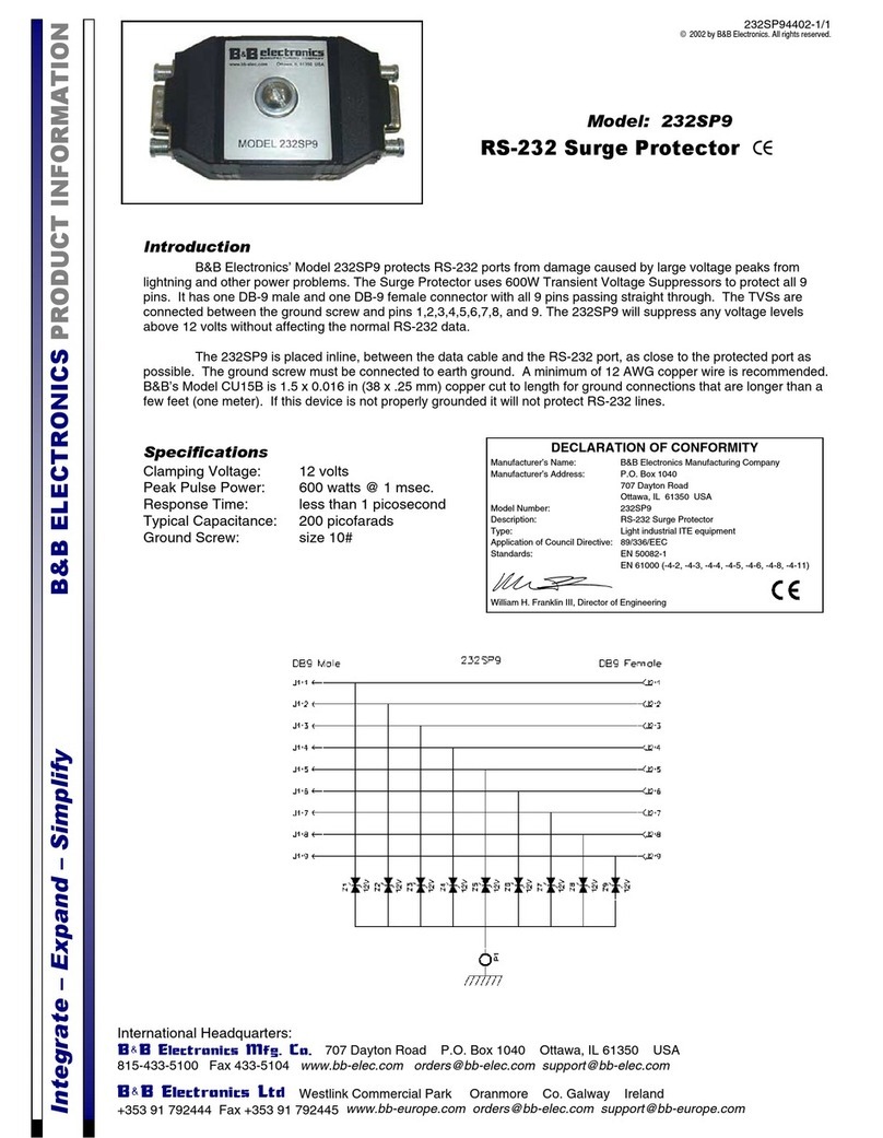
B&B Electronics 232SP9 Product information

B&B Electronics

B&B Electronics 232SP9 Product information

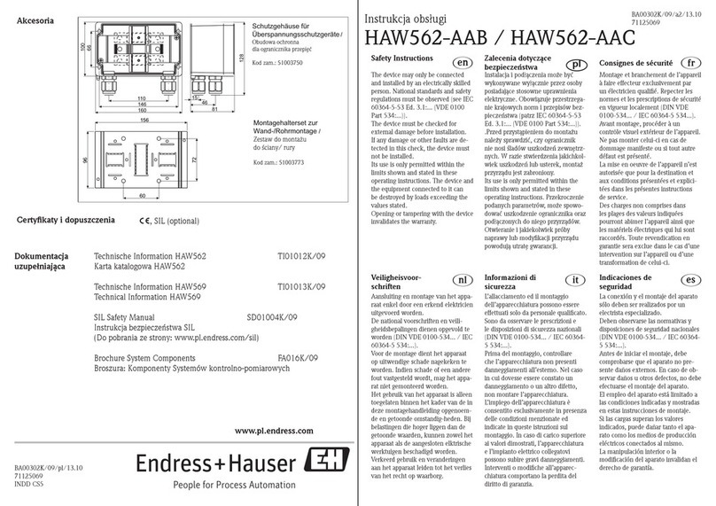
Endress+Hauser HAW562-AAB quick start guide

Endress+Hauser

Endress+Hauser HAW562-AAB quick start guide

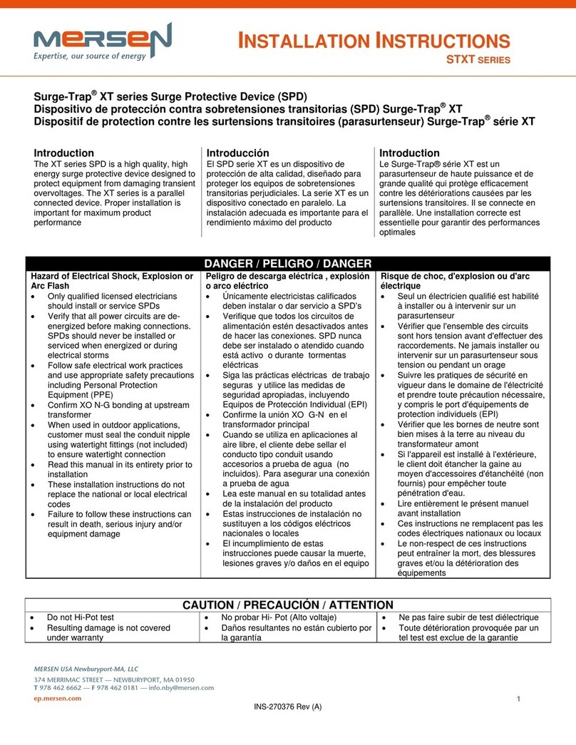
Mersen STXT Series installation instructions

Mersen

Mersen STXT Series installation instructions

Ilsco SSI SpecPRO CSM 52 Series manual

Ilsco

Ilsco SSI SpecPRO CSM 52 Series manual

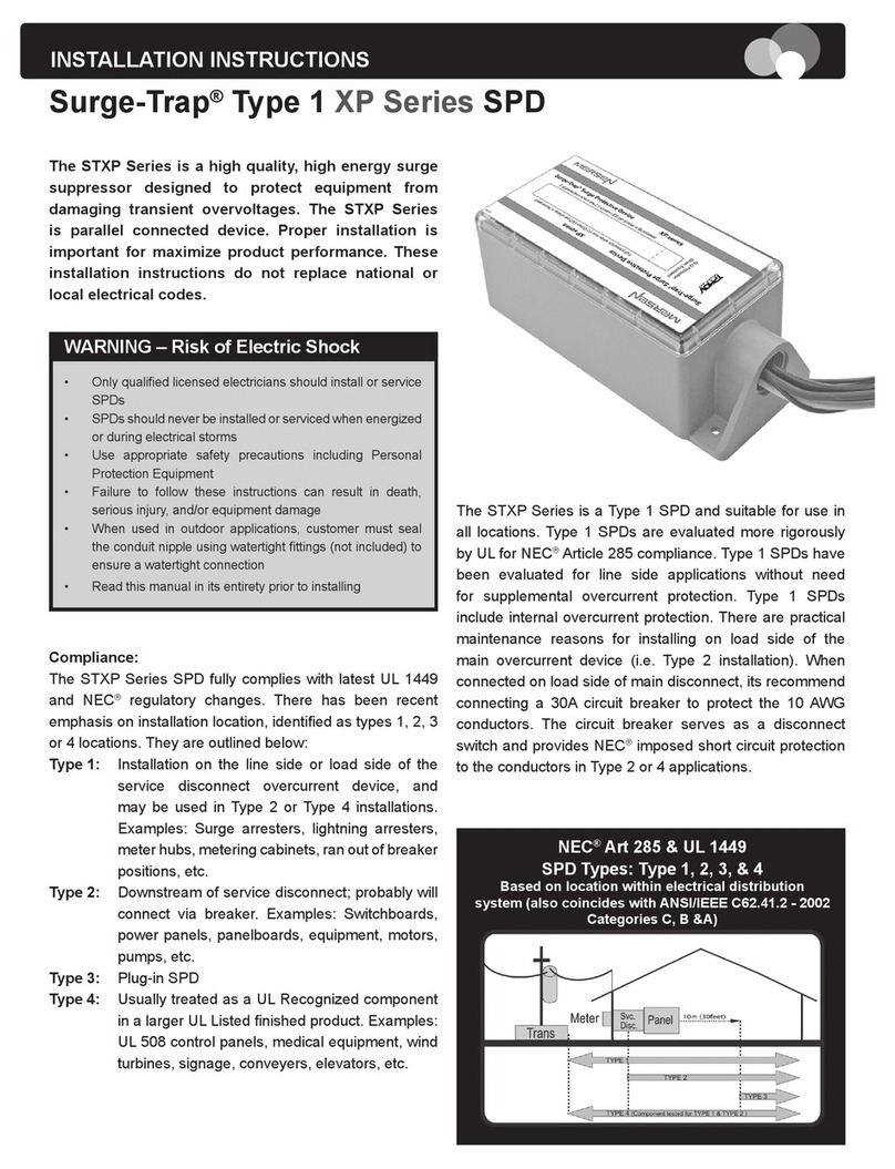
Mersen Surge-Trap XP Series installation instructions

Mersen

Mersen Surge-Trap XP Series installation instructions

Tripp Lite SK30USB owner's manual

Tripp Lite

Tripp Lite SK30USB owner's manual

Rocket Fish RF-PCS12ES13 Quick setup guide

Rocket Fish

Rocket Fish RF-PCS12ES13 Quick setup guide

Tripp Lite TLP82F Specifications

Tripp Lite

Tripp Lite TLP82F Specifications

Rocket Fish RF-HTS100 Guide d'installation rapide

Rocket Fish

Rocket Fish RF-HTS100 Guide d'installation rapide

Tripp Lite SUPER6OMNI Series owner's manual

Tripp Lite

Tripp Lite SUPER6OMNI Series owner's manual

Rocket Fish RF-HTS4018 Quick setup guide

Rocket Fish

Rocket Fish RF-HTS4018 Quick setup guide

Tripp Lite HT706TV owner's manual

Tripp Lite

Tripp Lite HT706TV owner's manual

Tripp Lite DEU2 TEL Specification sheet

Tripp Lite

Tripp Lite DEU2 TEL Specification sheet

Tripp Lite TLP725 Specifications

Tripp Lite

Tripp Lite TLP725 Specifications

M-TI BPT Series quick start guide

M-TI

M-TI BPT Series quick start guide

Rocket Fish RF-HTS115 Guide d'installation rapide

Rocket Fish

Rocket Fish RF-HTS115 Guide d'installation rapide

Tripp Lite TLP810SAT Specifications

Tripp Lite

Tripp Lite TLP810SAT Specifications

manuals.online logo
manuals.online logoBrands
  • About & Mission
  • Contact us
  • Privacy Policy
  • Terms and Conditions

Copyright 2025 Manuals.Online. All Rights Reserved.