2. Wiring Connection Diagrams
Figure 3 shows the electrical relationship between owProfile and these three basic service configurations:
Split phase, 3-wire, Three-phase, 4-wire WYE, and Three-phase, 4-wire high-leg Delta.
Connections to the SPD are clearly identified. Connections are made via pigtail leads supplied with the unit. For 3 phase
units phases A, B and C are black wires, which are marked “Phase A”, “Phase B” and “Phase C” respectively. For split phase
units, the phase connections are marked “Phase A” and “Phase B”. The neutral is a white wire and the ground is a
green/yellow wire.
3. Upstream Over-Current Protection Devices
The owProfile has been listed to U 1449 as a Type 1 SPD. Type 1 SPDs can be used in Type 1 or Type 2 SPD applications,
which means that the owProfile does not need to be connected behind an upstream over current protection device and can
be connected on either the line or load side of the main service disconnect. The owProfile must be connnected in parallel
with the electrical system. All owProfile units come standard with component-level over-current fusing rated at 200,000 rms
symmetrical amperes at 600VAC.
. Conductor Routing
The factors listed above should be addressed during the design of an installation to reserve a suitable place for owProfile
next to its point of connection to the electrical system. The selected mounting location should allow for the shortest possible
conductor runs and a direct route with a minimum of bends. If bends are required, they should be sweeping bends. Do not
make sharp 90° bends for appearance purposes because they will severely decrease the effectiveness of owProfile.
Braiding or twisting conductors together using tie-wraps or electrical tape increases the protection performance of the device.
One or two twists or braids of all conductors per foot and securely tie-wrap when conductor lengths must exceed 12”.
5. Conduit Openings
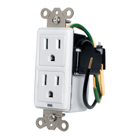
All P units come with a 3/4” conduit hub and chase nipple. There are three conduit openings located in top, top left, and
top right sides of the enclosure. The hub can be installed in any of the three openings. The remaining unused openings can
be covered with supplied knock-out seals.
LOWPROFILE™InstaLLatIOn, OPERatIOn and MaIntEnancE ManuaL
4
Fig. 1: Split Phase, 3-Wire
SPD
CAUTION: Do not splice Low Profile conductorswithin the unit’s enclosures or Manufacturer’s warranty will
be void. LowProfile’s performance will be limited severely if the conductors are (a) too long, (b) are of too small
a wire gauge, (c) have too many bends or (d) have sharp bends.
Fig. 2: 3-Phase, -Wire WYE
SPD
WARNING: Check to ensure that a proper bond is installed between neutral and ground at the transformer
upstream from all 3-phase WYE or split-phase LowProfile PD ( ee NEC Article 250). If the transformer is not
accessible, check the main service disconnect/panel for the N-G bond. Lack of a proper bond will damage
LowProfile and void the warranty.
Fig. 3: 3-Phase, -Wire High-Leg DELTA
SPD


