manuals.online logo
Brands
  1. Home
  2. •
  3. Brands
  4. •
  5. Total Protection Solutions
  6. •
  7. Surge Protector
  8. •
  9. Total Protection Solutions LoadTrack LTE AC Series User manual

Total Protection Solutions LoadTrack LTE AC Series User manual

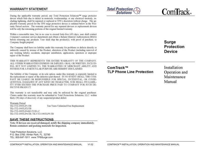
WARRANTY STATEMENT
During the applicable warranty period, any Total Protection Solutions™ surge protector
device which fails due to defect in materials, workmanship, or any electrical anomaly, in-
cluding lightning, shall be repaired or replaced at TPS’s discretion without charge. The ap-
plicable warranty period for the TPS surge protective device is outlined below in the War-
ranty Period section. The warranty period for any repaired devices or replacement devices
will be only the remaining portions of the original limited warranty.
Within a reasonable time, but in no case to exceed forty-five (45) days, user shall contact
Company's customer service department and obtain a Return Material Authorization (RMA)
before returning any products. User shall ship the product(s), with proof of purchase, to
Company freight prepaid.
The Company shall have no liability under this warranty for problems or defects directly or
indirectly caused by misuse of the Product, alteration of the Product (including removal of
any warning labels), accidents, improper installation, application, operation or improper
repair of the Product.
THIS WARRANTY REPRESENTS THE ENTIRE WARRANTY OF THE COMPANY.
ALL OTHER WARRANTIES EXPRESS OR IMPLIED, ORAL OR WRITTEN, INCLUD-
ING, BUT NOT LIMITED TO, THE WARRANTIES OF MERCHANT ABILITY AND
FITNESS FOR A PARTICULAR PURPOSE ARE HEREBY DISCLAIMED.
The liability of the Company, at its sole option, under this warranty is expressly limited to
the replacement or repair of the defective part thereof. IN NO EVENT SHALL THE COM-
PANY BE LIABLE OR RESPONSIBLE FOR SPECIAL, INCIDENTAL, OR CONSE-
QUENTIAL DAMAGES OF ANY KIND OR CHARACTER, NOR SHALL ITS LIABIL-
ITY EVER EXCEED THE PURCHASE PRICE PAID TO COMPANY FOR SUCH DE-
FECTIVE PRODUCT.
This warranty is not transferable and may only be enforced by the original purchaser.
Claims under this warranty must be submitted to Total Protections Solutions, LLC. within
thirty (30) days of discovery of any suspected product defect.
Warranty Period
TK-LTExxx-yyA-DIN2, Fifteen Years Unlimited Free Replacement
(xxx is the voltage, yy is the amperage)
SAVE THESE INSTRUCTIONS
Note: If devices are received damaged, notify the shipping company immediately.
Retain containers and packing materials for inspection.
LoadTrack™ LTE Models
AC & DC Series/Parallel
Power Applications
LOADTRACK™ INSTALLATION, OPERATION AND MAINTENANCE MANUAL LOADTRACK™ INSTALLATION, OPERATION AND MAINTENANCE MANUAL
L
oad
T
rack
™
Surge
Protection
Device
Installation
Operation and
Maintenance
Manual
Total Protection Solutions, LLC.
TEL: 800.647.1911 www.TPSsurge.com
P.O. Box 3760 Winter Park, FL 32790
NOTICE: All instructions and measurements must be completed by a qualified electrician in
accordance with the National Electric Code and/or other applicable state and local codes. The U.S.
National Electric Code and/or applicable state/local requirements supersede these instructions.
IMPORTANT SAFETY INSTRUCTIONS
Page: 3
CAUTION: HAZARDOUS VOLTAGES PRESENT
Improper installation or misapplication of these devices may result in serious injury to the installer
and/or damage to electrical system(s) or related equipment. Read and understand all instructions
before commencing with the installation. Protective eyewear should be worn during the installa-
tion process.
Page: 2
Units must be connected to the electrical service with appropriate ampacity Class T Fuse,
rated 300 V, or with a breaker with appropriate ampacity for the specific unit.
Equipment Safety Grounds MUST be run separately - not through the traces of the Surge
Protection Device.
INSTALLATION
1) This document provides detailed information on how to install and operate the LoadTrack of
Surge Protective Devices (SPDs).
2) Units should be installed per the information and illustrations provided herein. See above
WARNING.
3) The LoadTrack Series of Surge Protective Devices are installed/connected in either series or
parallel with the line and the equipment to be protected.
4) Identified or indicated Leads/Wires must be connected exactly with respect to the power
feeding/supplying the SPD and equipment. Failure to do so may result in damage to the SPD,
the equipment/system or pose a danger to personnel.
5) Incorrect installation may significantly impair the performance of the SPD. It is particularly
important that all installation procedures and guidelines be followed exactly.
6) Before starting any installation procedures, verify service voltages (AC or DC) with a volt
meter to ensure that the correct model has been selected for the supply voltage.
7) DO NOT INSTALL THE SPD IF MEASURED VOLTAGE EXCEEDS UNIT RATINGS.
8) The SPD MUST BE mounted in an enclosure to assure personnel safety from exposed
terminals.
9) REMOVE POWER FROM ELECTRICAL SYSTEM PRIOR TO INSTALLATION.
10) The SPD should be positioned as the last device in the circuit prior to protected
equipment.
11) The SPD Line/Load designations are for orientation purposes only and do not effect the
install.
ANY ALTERATIONS, TAMPERING, MISUSE OR UNAUTHORIZED REPAIRS OF THIS PRODUCT
WILL VOID ITS ORIGINAL FACTORY WARRANTY.
WARNING
WIRING DIAGRAMS
NOTE: Circuit Protection NOT required for neutral application.
If two (2) hots are used a second interrupt device is required.
Load out
Line in
Load out
Line2 / N in
Line2 / N out
Line2 / N out
Ground out
Ground out
Not a safety
Ground
Not a safety
Ground
Ground
Ground
Ground
Ground
Series
Series
Parallel
Parallel
(Fuse incoming lines)
(Fuse incoming
lines) Line in
Line2 / N in
(Fuse incoming lines)
Line
Line2 / N
(Fuse incoming lines)
Line
Line2 / N
12) Mechanically mount the SPD utilizing the mounting tabs or attach to din rail.
13) For Series (AC) Applications
a) Connect "LINE" Side:
∗System Ground to the terminal labeled "G".
* Neutral or Line 2 wire to the terminal labeled "L2" .
* HOT wire to the terminal labeled "L1".
b) Connect "LOAD" Side:
* System Ground to the terminal labeled “G" (connect safety ground directly to enclosure
ground).
* Neutral or Line 2 wire to the terminal labeled "L2".
* HOT wire to the terminal labeled “L1".
14) For parallel (AC) Applications, keeping leads as short as possible -
∗System Ground, to the terminal labeled "G".
* Neutral or Line 2 wire to the terminal labeled "L2".
* HOT wire to the terminal labeled "L1".
Note: In parallel applications, units are not current limited as they are in series applications.
For parallel applications, unused output terminals are left empty, no plugs are provided.
15) ENSURE THAT ALL CONNECTIONS ARE CORRECT BEFORE ENERGIZING.
16) Apply power (energize). LED indicator should illuminate. If light fails to illuminate contact
supplier. If LED is out, unit requires service.
17) Keep this MANUAL in a safe dry place for future reference.

This manual suits for next models

1

Other Total Protection Solutions Surge Protector manuals

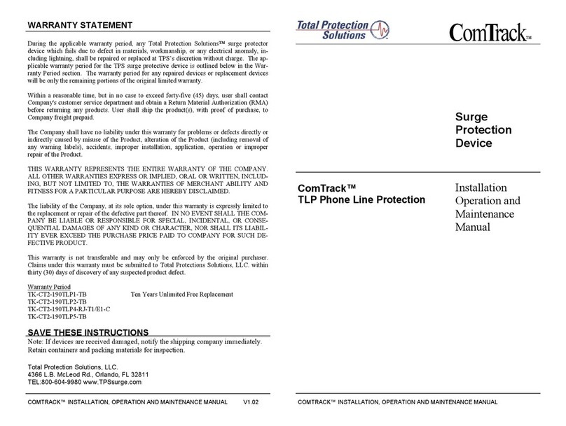
Total Protection Solutions ComTrack TK-CT2-PHONE-RJ Manual

Total Protection Solutions

Total Protection Solutions ComTrack TK-CT2-PHONE-RJ Manual

Total Protection Solutions ComTrack TK-CT2-DB9 User manual

Total Protection Solutions

Total Protection Solutions ComTrack TK-CT2-DB9 User manual

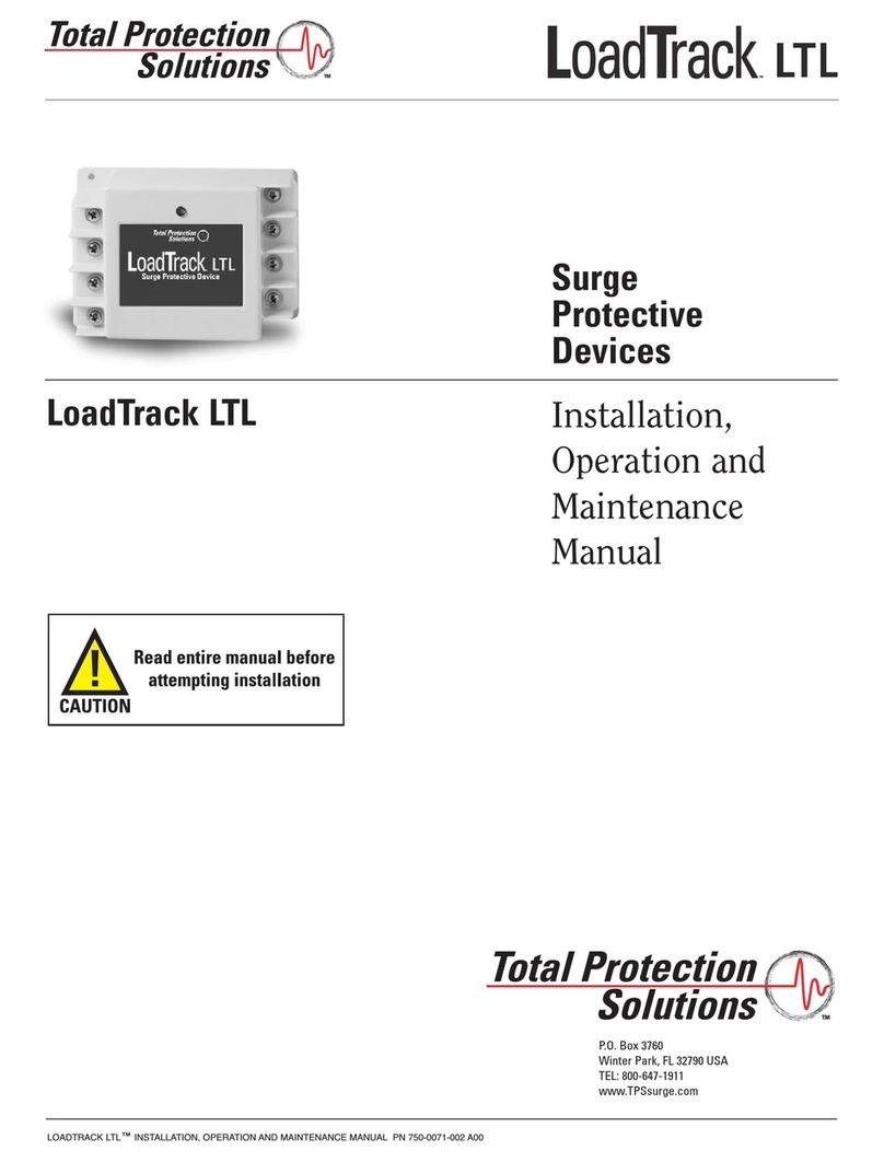
Total Protection Solutions LoadTrack TK-LTL120P-30A User manual

Total Protection Solutions

Total Protection Solutions LoadTrack TK-LTL120P-30A User manual

Total Protection Solutions 200 User manual

Total Protection Solutions

Total Protection Solutions 200 User manual

Total Protection Solutions 160 User manual

Total Protection Solutions

Total Protection Solutions 160 User manual

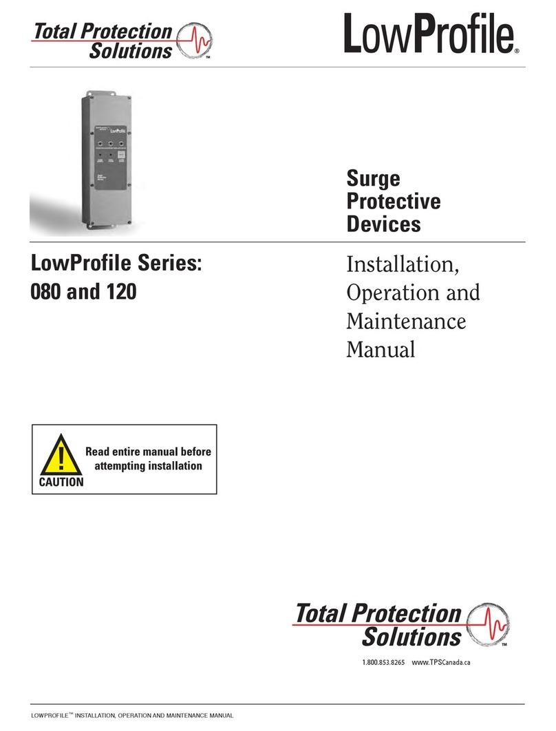
Total Protection Solutions 80 User manual

Total Protection Solutions

Total Protection Solutions 80 User manual

Total Protection Solutions ServiceTrack ST 080 User manual

Total Protection Solutions

Total Protection Solutions ServiceTrack ST 080 User manual

Total Protection Solutions TK-CT2-190TLP1-TB User manual

Total Protection Solutions

Total Protection Solutions TK-CT2-190TLP1-TB User manual

Total Protection Solutions 80 User manual

Total Protection Solutions

Total Protection Solutions 80 User manual

Total Protection Solutions ComTrack TK-CT2-190TLP4-RJ-T1/E1-C User manual

Total Protection Solutions

Total Protection Solutions ComTrack TK-CT2-190TLP4-RJ-T1/E1-C User manual

Popular Surge Protector manuals by other brands

Monster Power Home Theatre In-Wall PowerCenter 15 AMP owner's manual

Monster Power

Monster Power Home Theatre In-Wall PowerCenter 15 AMP owner's manual

Siemens 5SD7483-6RC operating instructions

Siemens

Siemens 5SD7483-6RC operating instructions

Ditek D200-347/6003Y Install instructions

Ditek

Ditek D200-347/6003Y Install instructions

PS Audio Ultimate Outlet Operation manual

PS Audio

PS Audio Ultimate Outlet Operation manual

Outback Power Systems FLEXWARE FW-SP-250 user guide

Outback Power Systems

Outback Power Systems FLEXWARE FW-SP-250 user guide

Clamper Solar SB 1040V 16A 4E/2S P18 installation guide

Clamper

Clamper Solar SB 1040V 16A 4E/2S P18 installation guide

Joslyn JSP series Installation, operation and maintenance guide

Joslyn

Joslyn JSP series Installation, operation and maintenance guide

Newpoint RX50TA operating manual

Newpoint

Newpoint RX50TA operating manual

dehn DEHNbox DBX TC 180 manual

dehn

dehn DEHNbox DBX TC 180 manual

TrickleStar TS1205 manual

TrickleStar

TrickleStar TS1205 manual

PROCET PT-PR01G-DIN Quick installation guide

PROCET

PROCET PT-PR01G-DIN Quick installation guide

ABB REU615 Applications manual

ABB

ABB REU615 Applications manual

Eaton BSPM2275TN instruction sheet

Eaton

Eaton BSPM2275TN instruction sheet

Dynex DX-S114251 Quick setup guide

Dynex

Dynex DX-S114251 Quick setup guide

Malmbergs EMP306SA instruction manual

Malmbergs

Malmbergs EMP306SA instruction manual

M-system MDK-24 instruction manual

M-system

M-system MDK-24 instruction manual

CablesPlus GoldX PowerCore user guide

CablesPlus

CablesPlus GoldX PowerCore user guide

RectorSeal RSH-50 installation instructions

RectorSeal

RectorSeal RSH-50 installation instructions

manuals.online logo
manuals.online logoBrands
  • About & Mission
  • Contact us
  • Privacy Policy
  • Terms and Conditions

Copyright 2025 Manuals.Online. All Rights Reserved.