manuals.online logo
Brands
  1. Home
  2. •
  3. Brands
  4. •
  5. Mersen
  6. •
  7. Surge Protector
  8. •
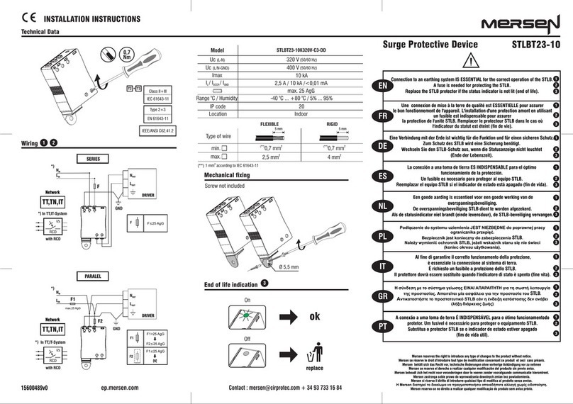
  9. Mersen Surge-Trap XP Series User manual

Mersen Surge-Trap XP Series User manual

The STXP Series is a Type 1 SPD and suitable for use in
all locations. Type 1 SPDs are evaluated more rigorously
by UL for NEC®Article 285 compliance. Type 1 SPDs have
been evaluated for line side applications without need
for supplemental overcurrent protection. Type 1 SPDs
include internal overcurrent protection. There are practical
maintenance reasons for installing on load side of the
main overcurrent device (i.e. Type 2 installation). When
connected on load side of main disconnect, its recommend
connecting a 30A circuit breaker to protect the 10 AWG
conductors. The circuit breaker serves as a disconnect
switch and provides NEC®imposed short circuit protection
to the conductors in Type 2 or 4 applications.
The STXP Series is a high quality, high energy surge
suppressor designed to protect equipment from
damaging transient overvoltages. The STXP Series
is parallel connected device. Proper installation is
important for maximize product performance. These
installation instructions do not replace national or
local electrical codes.
Compliance:
The STXP Series SPD fully complies with latest UL 1449
and NEC®regulatory changes. There has been recent
emphasis on installation location, identied as types 1, 2, 3
or 4 locations. They are outlined below:
Type 1: Installation on the line side or load side of the
service disconnect overcurrent device, and
may be used in Type 2 or Type 4 installations.
Examples: Surge arresters, lightning arresters,
meter hubs, metering cabinets, ran out of breaker
positions, etc.
Type 2: Downstream of service disconnect; probably will
connect via breaker. Examples: Switchboards,
power panels, panelboards, equipment, motors,
pumps, etc.
Type 3: Plug-in SPD
Type 4: Usually treated as a UL Recognized component
in a larger UL Listed nished product. Examples:
UL 508 control panels, medical equipment, wind
turbines, signage, conveyers, elevators, etc.
WARNING – Risk of Electric Shock
• Only qualied licensed electricians should install or service
SPDs
• SPDs should never be installed or serviced when energized
or during electrical storms
• Use appropriate safety precautions including Personal
Protection Equipment
• Failure to follow these instructions can result in death,
serious injury, and/or equipment damage
• When used in outdoor applications, customer must seal
the conduit nipple using watertight ttings (not included) to
ensure a watertight connection
• Read this manual in its entirety prior to installing
NEC®Art 285 & UL 1449
SPD Types: Type 1, 2, 3, & 4
Based on location within electrical distribution
system (also coincides with ANSI/IEEE C62.41.2 - 2002
Categories C, B &A)
Surge-Trap®Type 1 XP Series SPD
INSTALLATION INSTRUCTIONS
2
V
Hazardous voltage.
Will cause death or serious injury.
KEEP OUT.
Qualied personnel only.
Disconnect and lock off all power before working
on this equipment.
VDANGER
Figure 2 Dimensions & Weight
Device Operation
SPDs sense overvoltage conditions and create a momentary
short circuit to redirect harmful surge energy to earth ground,
resetting automatically waiting for the next surge. Operation
is similar to a pressure relief valve on a water heater: pressure
builds, valve opens to relieve pressure, resets when pressure
drops. SPDs are capable of repeating this function thousands
of times before needing replacement.
Voltage Rating & Application:
Before installing your STXP, verify by nameplate voltage or
model number that it has the same voltage rating as the
power distribution system. DO NOT INSTALL ANY LOWER
VOLTAGE RATED PRODUCT. See attached Advisor Data
Sheet or call Mersen Technical Services at (978) 465-4853
for help.
The system conguration is dened by the secondary
windings of the transformer supplying the service entrance
main or load. This includes whether or not the transformer
windings are referenced to earth via a grounding conductor.
The system conguration is not based on any specic load
or equipment connection. SPDs should be installed per
the distribution system, not per a load or motor’s wiring
connection. For example: A 480V three phase motor
appears to be connected in 480V Delta. In reality, the
distribution system is congured as a 480Y/277V grounded
Wye, with or without a neutral pulled to the motor or MCC.
The system is a 480Y/277V Wye, even though the load
is connected as a Delta. A grounded Wye has a dened
reference to ground (i.e., neutral is bonded to ground). In
contrast, some Delta systems are ungrounded, which have
no reference to ground.
WARNING SPDs on Ungrounded Systems
Caution – Ungrounded systems are inherently unstable
and can produce excessively high line-to-ground voltages
during certain fault conditions. During these fault conditions,
any electrical equipment including SPDs, may be subjected
to voltages which exceed their designed ratings. This
information is being provided to the user so that an informed
decision can be made before installing any electrical
equipment on an ungrounded power system.
STXP Series SPDs have high SCCR (short circuit
current ratings) capacity including the lead conductors.
Supplemental overcurrent protection is not required to
protect your STXR SPD. However, NEC®convention
requires that connecting conductors have overcurrent
protection in Type 2 or 4 applications. Follow applicable
codes. Your STXP device features internal overcurrent and
over temperature protection that will disconnect effected
surge suppression components at end of life. Power to the
load is maintained but unprotected and the STXR should
be replaced as soon as possible. The STXP SPD is factory
sealed and contains no serviceable parts.
3.00
(76.20)
0.19
(4.83)
8.28
(210.31)
3.67
(93.22)
2.21
(56.13)
7.41
(188.21)
Weight: 3lbs (1.4kg)
3
Typical Panel Installation
(Type 1 or individual equipment installations may vary)
Use closest breaker to SPD Locate
SPD close to intended breaker
Keep Leads Short as Possible
Avoid Sharp Bends
Rotate XP Series
such that LED
indicator is most
visible
Outdoor installation requires
appropriate weather sealing
at the nipple
To Protected Loads
Figure 3
Leads: Short & Straight:
Cut excess; Do not coil or loop
Not Good
GOOD
XCut off Excess
Length
Do Not Loop
or Coil
Short &
Straight
Figure 4
INSTALLATION:
Plan your installation and accomplish the following:
• Meet all National and Local codes (NEC®Article 285
and UL 1449 address SPDs).
• Conrm System voltage to SPD voltage (120V SPD will
fail instantly on 240V, 277V, etc.).
• Mount STXP as close to panel or equipment as possible,
keeping leads as short as possible.
• Ensure leads are as short and straight as possible,
including neutral and ground. If using a breaker, use a
breaker position closest to SPD and panel’s neutral &
ground.
• If using a breaker, recommended breaker size is 30A
due to 10 AWG conductor.
• Make sure system is grounded per NEC®and clear of
faults before energizing SPD.
• Never Hi-Pot test any SPD. Product will fail prematurely.
• Do not install the STXP through the bottom of a NEMA
3R panel. Dripping water will prematurely fail the SPD.
(A sealed pipe nipple installed in the SPD may be a
solution.)
1. Use voltmeter to check voltages and ensure correct
SPD. See Data Sheet for specs & wire-outs.
2. Determine mounting method (See Figure 3) – weather
resistant equipment may be required.
3. If SPD has optional Dry Contact, pre-plan its installation.
4. Remove power from panel/source. Conrm panel and
all sources are de-energized.
5. Identify breaker location and SPD location. Position
SPD such that LED is best visible.
6. Mount SPD – weather resistant applications require
additional sealing, o-rings, etc. (not included).
• Remove an appropriately sized knockout from panel.
• Connect conductors as appropriate – short and
straight as possible (Hi-Legs are Phase B).
7. Label or mark conductors as appropriate (Neutral: White,
Ground: Green, Energized: Black, Hi-Leg: Orange).
8. Make sure system is bonded per NEC®and is clear of
hazards or faults before energizing (N-G bonding not
per NEC®will fail SPDs: #1 cause of SPD failures).
9. Energize and conrm proper operation of green LED
indicator and/or options.
Figure 5
VWARNING
• Conrm XO N-G Bonding at Upstream Transformer
• Do Not Hi-Pot Test
• Resulting Damage is not Covered Under Warranty
SPD
Hex Standoff
(4 Provided)
Mounting Surface
Mounting Screws
(4 Places, Not Provided)
Flush Mount Kit Screws
(8 Provided)
Phase,Ground,
Neutral Wires
Flush Mount Plate
Removed Material
European Authorized Representative
Obelis s.a.
Boulevard Général Wahis 53
1030 Brussels, BELGIUM
Tel: +(32) 2. 732.59.54
Fax: +(32) 2. 732.60.03
E-Mail: [email protected]
Conrm XO N-G Bonding at Upstream Transformer
Do Not Hi-Pot Test
Resulting Damage is not Covered Under Warranty
WARNING
V
WARNING
!
VERIFY THAT ALL POWER CIRCUITS ARE DE-ENERGIZED BEFORE
MAKING CONNECTIONS
All electrical connections should be performed by a qualied (licensed) electrician or
technician. All wiring must comply with the National Electrical Code (NEC®) and applicable
local codes.
Normally Closed (suggested):
Use Gray and Red
Normally Open:
Use Gray and Blue
© 2010 Mersen USA Newburyport-MA, LLC. All rights reserved.
USA T 978 462 6662 F 978 462 0181 [email protected]
CANADA T 416 252 9371 F 416 252 6572 [email protected]
ep-us.mersen.com
Connecting Optional Form C Dry Contact &
Audible Alarm
Three (3) 3’ (~1m) 18 AWG wires are included through
the nipple with this option. (These are smaller than
the 10 AWG SPD conductors.) Gray is Common, Blue
is Normally Open and Blue is Normally Closed. (We
generally recommend the Normally Closed conguration
because it detects disconnected or failed wiring
whereas Normally Open does not.) If the Dry Contacts
are not utilized, insulate lead ends, coil and secure.
Audible Alarm will still function correctly. The contact
is rated 250V, 5A. Higher energy applications require
supplemental relaying. This option monitors suppression
element condition and is not intended for use as phase
loss or phase detection monitoring.
NORMAL OPERATION
Green LED Indicator:
LED indicator illuminates when SPD is energized and
operating correctly. Every suppression component
is connected via logic to the green LED. Should any
suppression component fail, green LED will extinguish.
Form C Dry Contact and Audible Alarm Option
Dry Contact will change state and Audible Alarm will sound
upon any suppression component failure. The Audible
Alarm will be silenced by removing power to the SPD.
Maintenance:
SPDs require minimal maintenance. Periodic inspection
of diagnostic indicator is suggested to ensure proper
operation.
Troubleshooting & Service
Please contact Mersen Technical Services for any service
related issues.
#9009
Blue Gray
Red
Dry Contact
Leads
(18 AWG)
Power Leads
(10AWG)
Figure 6

This manual suits for next models

4

Other Mersen Surge Protector manuals

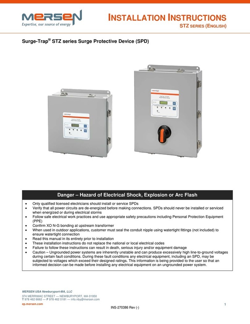
Mersen Surge-Trap STZ series User manual

Mersen

Mersen Surge-Trap STZ series User manual

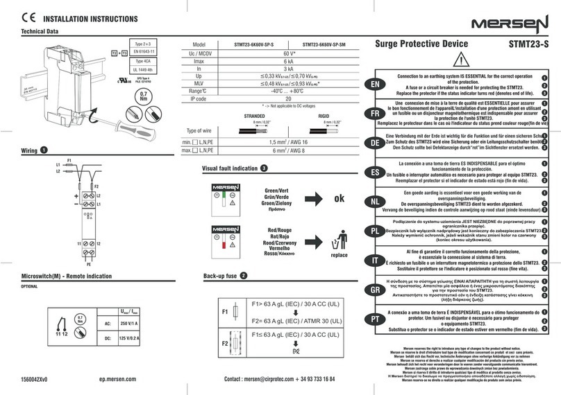
Mersen STMT23-S Series User manual

Mersen

Mersen STMT23-S Series User manual

Mersen Surge-Trap User manual

Mersen

Mersen Surge-Trap User manual

Mersen Surge-Trap STP Series User manual

Mersen

Mersen Surge-Trap STP Series User manual

Mersen Surge-Trap User manual

Mersen

Mersen Surge-Trap User manual

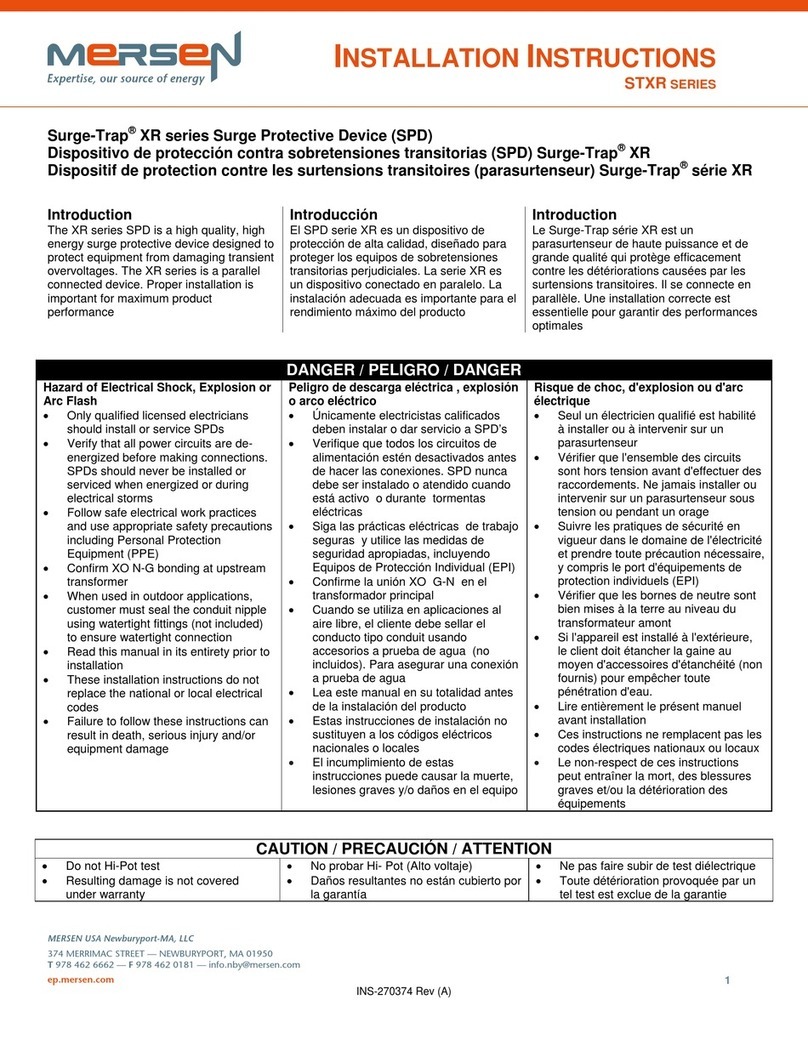
Mersen Surge-Trap XR Series User manual

Mersen

Mersen Surge-Trap XR Series User manual

Mersen Surge-Trap User manual

Mersen

Mersen Surge-Trap User manual

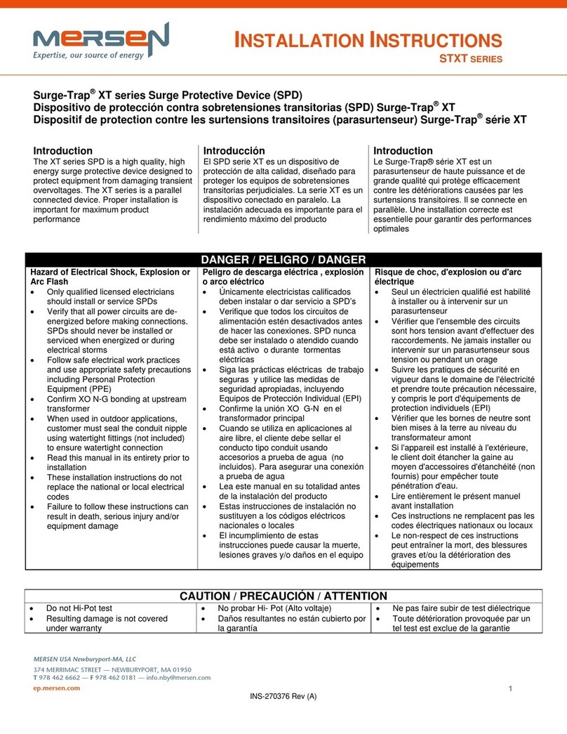
Mersen STXT Series User manual

Mersen

Mersen STXT Series User manual

Mersen Surge-Trap ST-50 Series User manual

Mersen

Mersen Surge-Trap ST-50 Series User manual

Mersen STLBT23-10 User manual

Mersen

Mersen STLBT23-10 User manual

Popular Surge Protector manuals by other brands

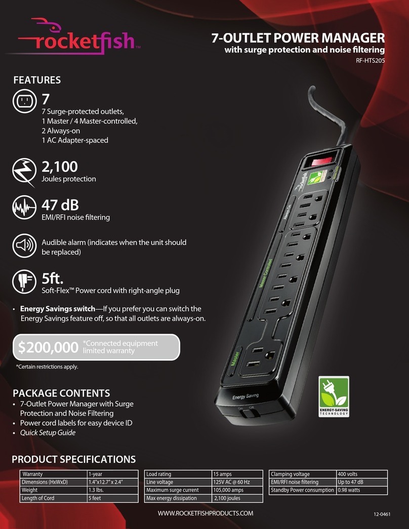
Rocket Fish RF-HTS205 specification

Rocket Fish

Rocket Fish RF-HTS205 specification

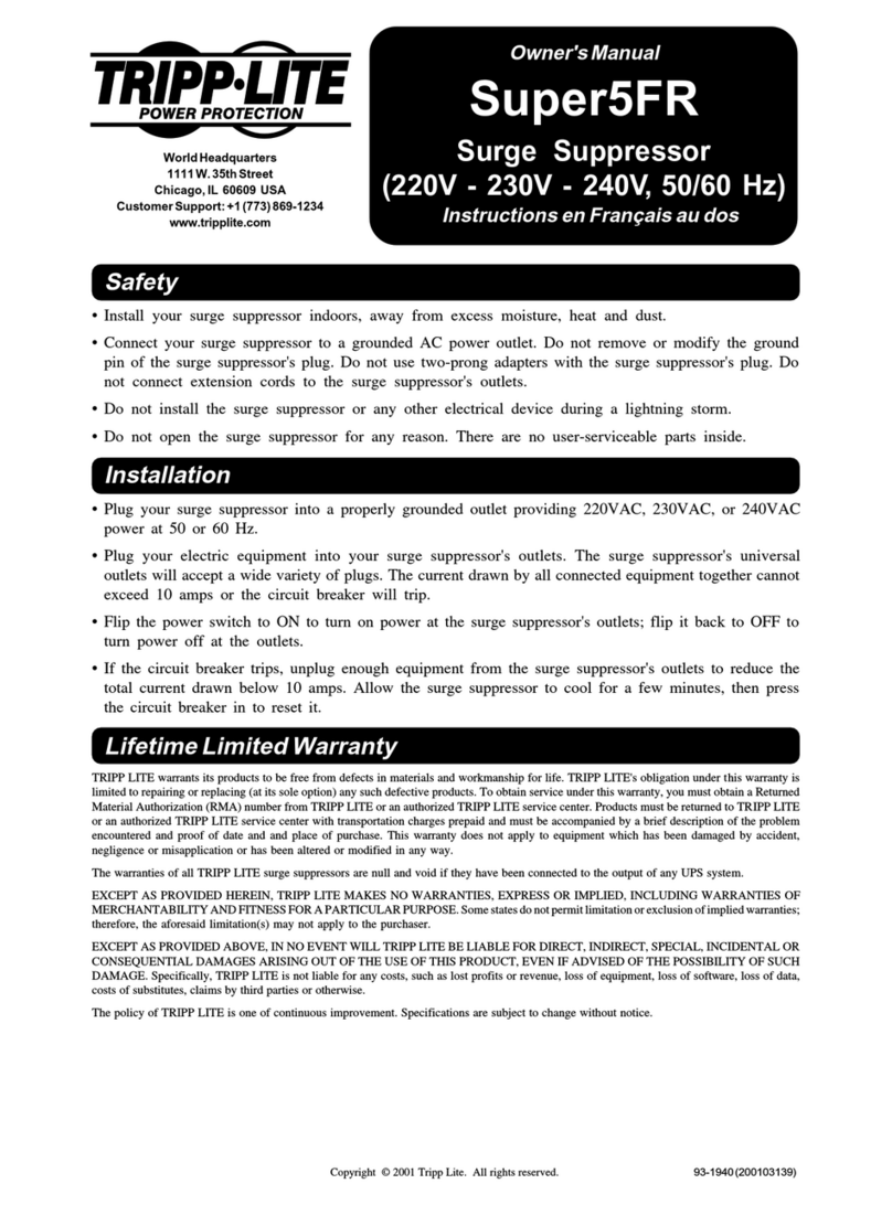
Tripp Lite Super5FR owner's manual

Tripp Lite

Tripp Lite Super5FR owner's manual

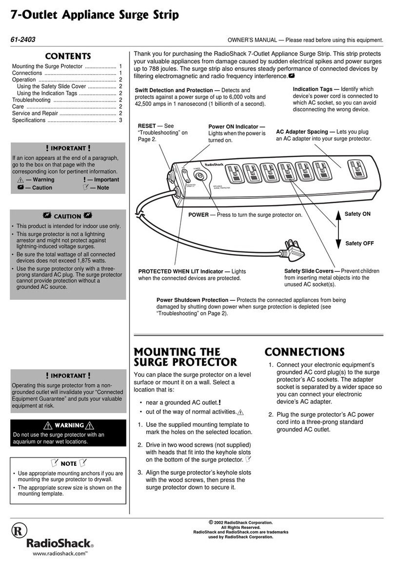
Radio Shack Surge Protector owner's manual

Radio Shack

Radio Shack Surge Protector owner's manual

Monster Power Professional PowerCenter Pro 2500 owner's manual

Monster Power

Monster Power Professional PowerCenter Pro 2500 owner's manual

Philips Xtreme Surge Protector I Design-in guide

Philips

Philips Xtreme Surge Protector I Design-in guide

SurgeX XQ515 user manual

SurgeX

SurgeX XQ515 user manual

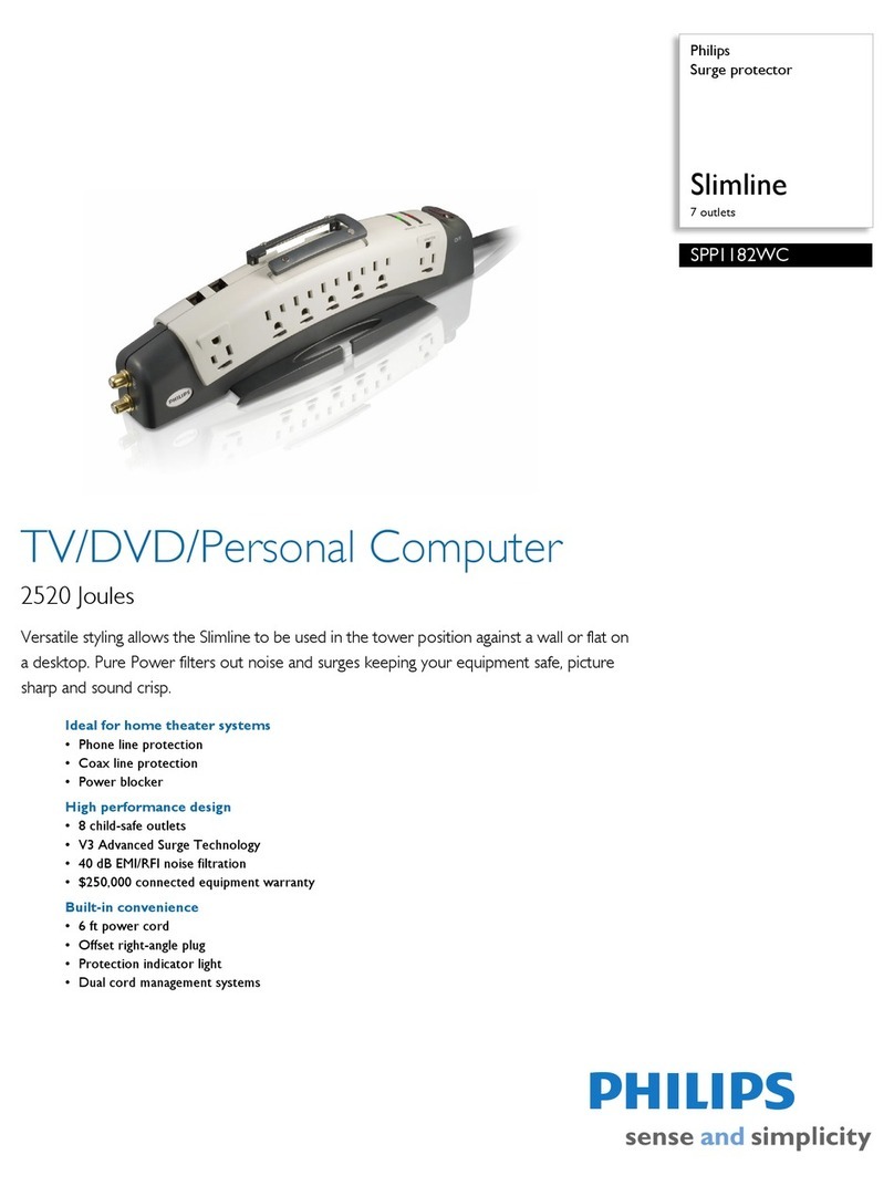
Philips SPP1182WC Specifications

Philips

Philips SPP1182WC Specifications

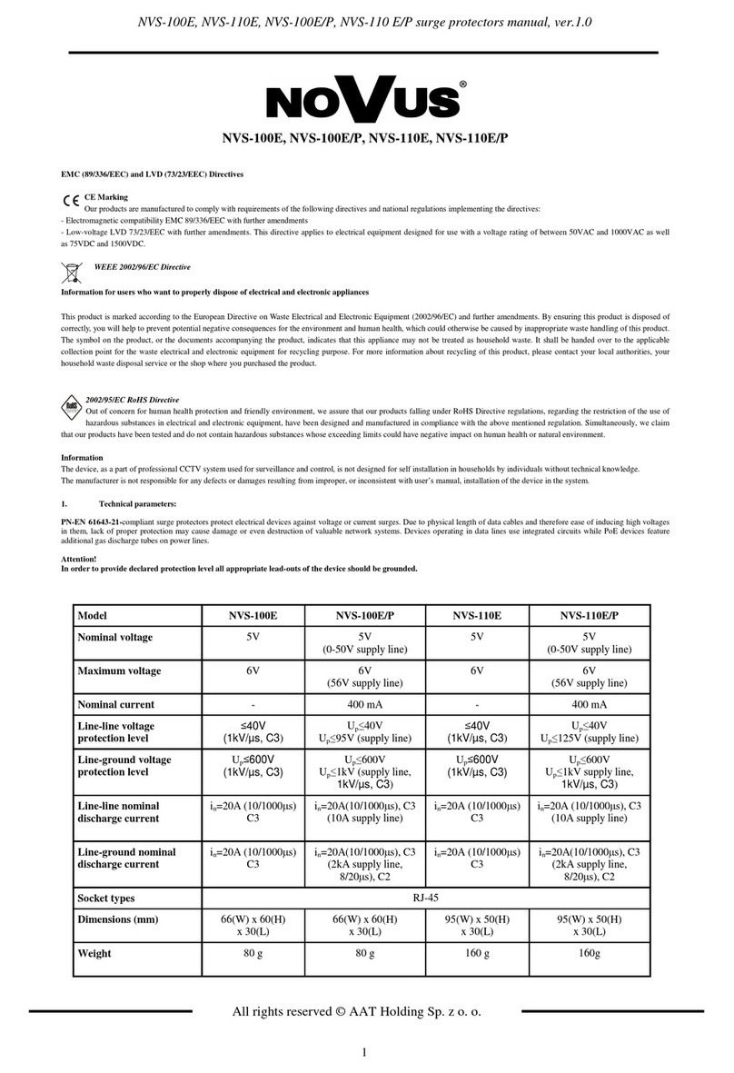
Novus NVS-100E manual

Novus

Novus NVS-100E manual

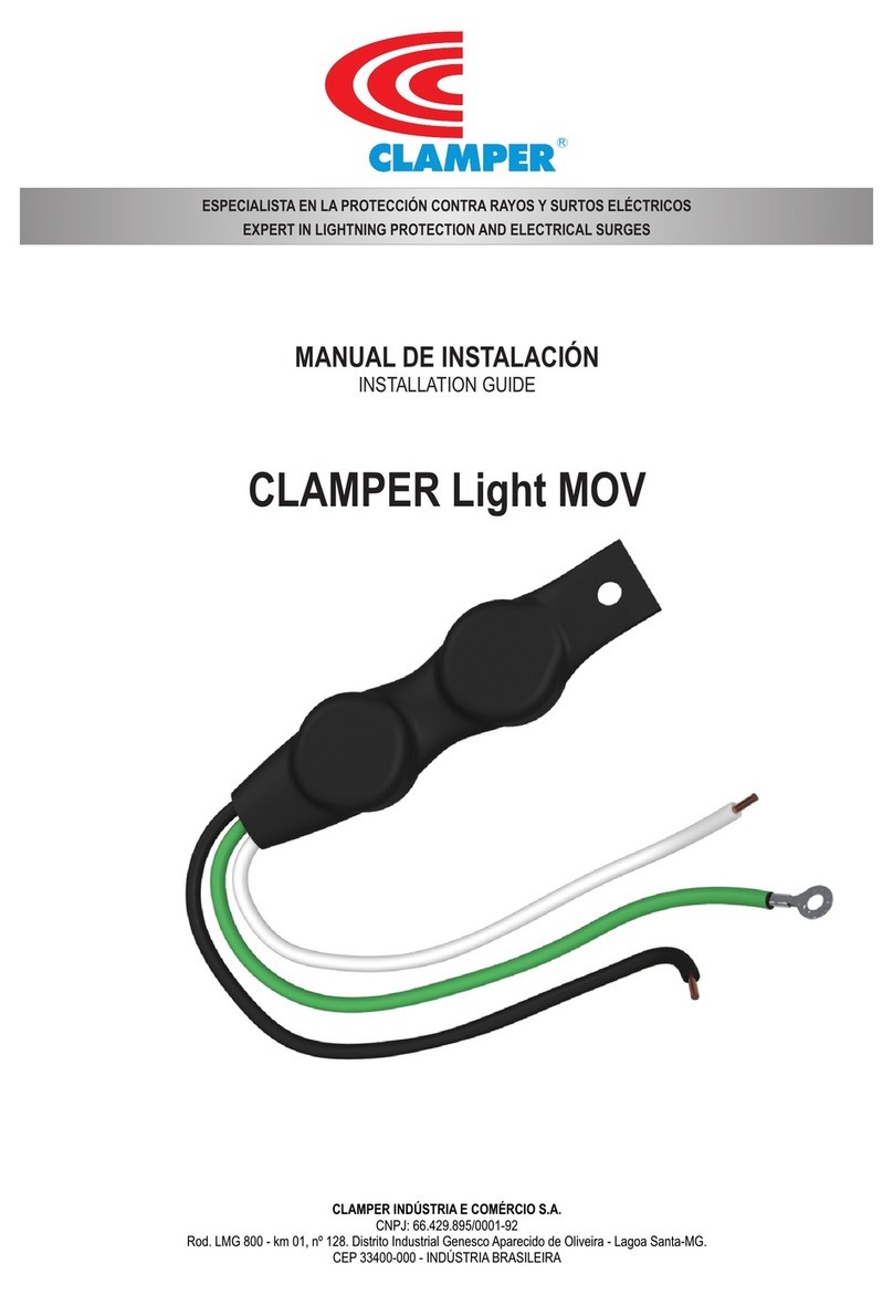
Clamper Light MOV 12P installation guide

Clamper

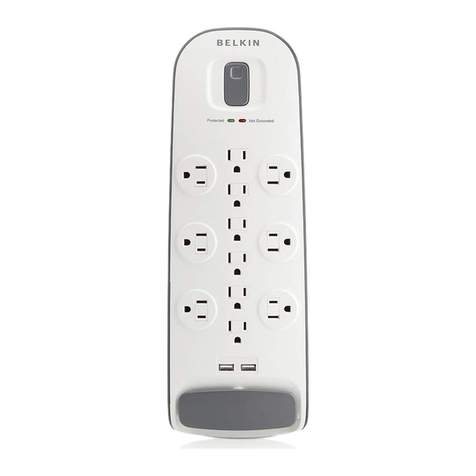
Clamper Light MOV 12P installation guide

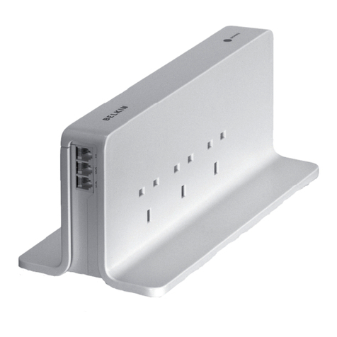
Belkin BZ106200IR2M user manual

Belkin

Belkin BZ106200IR2M user manual

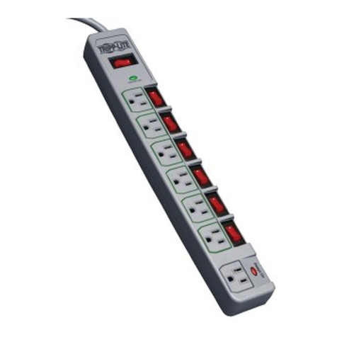
Tripp Lite TLP76MSG Specifications

Tripp Lite

Tripp Lite TLP76MSG Specifications

QVS PP135 Specification sheet

QVS

QVS PP135 Specification sheet

Eaton SPBT12-280/3 Instruction leaflet

Eaton

Eaton SPBT12-280/3 Instruction leaflet

Belkin BV101 Series Basic installation instructions

Belkin

Belkin BV101 Series Basic installation instructions

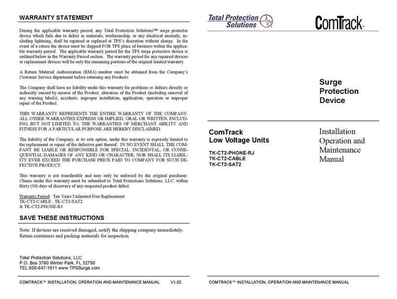
Total Protection Solutions ComTrack TK-CT2-PHONE-RJ Installation, operation and maintenance instructions

Total Protection Solutions

Total Protection Solutions ComTrack TK-CT2-PHONE-RJ Installation, operation and maintenance instructions

Panamax In-Wall Home Theater Power Management Specification sheet

Panamax

Panamax In-Wall Home Theater Power Management Specification sheet

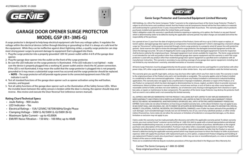
Genie GSP manual

Genie

Genie GSP manual

Siemens HNM3M120 manual

Siemens

Siemens HNM3M120 manual

manuals.online logo
manuals.online logoBrands
  • About & Mission
  • Contact us
  • Privacy Policy
  • Terms and Conditions

Copyright 2025 Manuals.Online. All Rights Reserved.