6. Conduit Openings
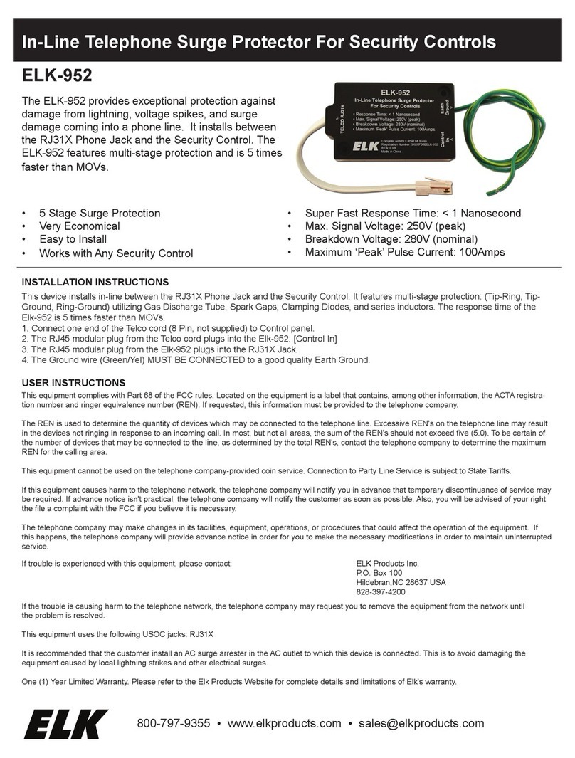
Note the hub supplied with the unit, when properly installed, ensures the enclosure maintains its NEMA 4 rating.
All conduits and fittings must be rated and properly installed such that the final installation maintains a NEMA 4 rating.
Punch holes in locations indicated in Figure 6 for the conduit hub.
7. Mounting
ServiceTrack ST SPD
For convenience all units are shipped with a mounting kit consisting of a hub, chase nipple, offset nipple, lock washers
and wire bushing. Use the construction methods and hardware appropriate for your site. Install the conduit hub and other
supplied hardware. Install conductors according to sections 4, 5 and 6, herein. See Figure 6 for enclosure and mounting
dimensions.*
ServiceTrack ST Disconnect Switch Options
See the ServiceTrack ST Disconnect Switch Installation and Operations Manual for the proper mounting methods.
*Recommen avoi ing wire-pulling lubricant ue to potential for insulation eterioration, especially on such a short, small con uctor installation.
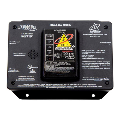
1. Phase, Neutra , and Ground Connections
NOTE: In order to connect the ServiceTrack ST, the cover of the unit must be removed. Use care when removing the cover,
on the backside of the cover) has a cable harness which routes into the enclosure. Additionally there is a ground jumper
between the enclosure and the cover. Units supplied with a surge counter have a harness, which runs from the surge counter
display to a core inside the unit.
Following all applicable National Electrical Code standards as well as state and local codes, connect phase, neutral* and
ground to ServiceTrack ST. If suppressor is being installed on a breaker, installation electrician should install device directly
adjacent to the breaker feeding the device to insure conductor length is kept to a minimum. The 80ka is supplied with #10
AWG conductors permanently attached. hould mounting conditions require extension of the supplied conductor(s), installa-
tion electrician may use a butt-splice or parallel solder with shrink-tube installation. In no event shall the electrician use a
wire nut to make the extension as this will result in loss of suppressor’s performance. Ensure that the conductor lengths are
kept as short and straight as possible. The 120kA to 400kA units come with lugs that can be rotated to face in the direction of
the cable exit by loosening the nut on the input terminal lugs in the SPD. Tighten all lugs to 20in-lb (2.2Nm). On all high-
leg delta systems, the high-leg (color-coded orange according to NEC) must be connected to the Phase B of the SPD.
* The 3-wire plus groun Delta ServiceTrack ST oes not have a neutral con uctor.
CONNECTION AND WIRING INSTRUCTIONS
sERVICEtRaCk st®InstallatIon, opERatIon and MaIntEnanCE Manual 7
rating of the erviceTrack T unit being installed. Do not splice erviceTrack T conductors within the unit’s
enclosure or Manufacturer’s warranty will be void.
!
The 80kA unit comes with a 3/4” conduit hub. This hub requires a 1- 1/8” diameter hole for proper installation.
Note the hub supplied with the unit, when properly installed, ensures the enclosure maintains its NEMA 4 rating.
The 120kA to 400kA units come with a 1”conduit hub. This hub requires a 1-11/32” diameter hole for proper installation.
CAUTION: Prior to installation ensures the system configuration and voltage are equivalent to the voltage
as there are wires which run from components on the cover to inside the enclosure of the SPD. The monitor board (located
There are no position-oriented components. Unit may be installed in whatever position allows shortest conductor length
to point of termination
Note: Disconnect SPD from electrical system prior to and during any Hipot testing


