TOTALINE P102-12 Manual
Manufacturer reserves the right to
discontinue, or change at any time,
specifications or designs without notice
and without incurring obligations.
REPLACEMENT COMPONENTS DIVISION LITERATURE NUMBER P102-2SI
© CARRIER CORPORATION 2002 3/02 REPLACES: EAC-50SI
PRINTED IN U.S.A. CATALOG NUMBER 570-476
Part Numbers: P102-12, P102-14A, P102-14B, P102-20
IF YOU NEED HELP call toll free: 1-800-267-8305
CONTENTS
SAFETY CONSIDERATIONS . . . . . . . . . . . . . . . . . . . . . . 1
GENERAL . . . . . . . . . . . . . . . . . . . . . . . . . . . . . . . . . . . . . . . . 1
COMPONENTS . . . . . . . . . . . . . . . . . . . . . . . . . . . . . . . . 1,2
Cabinet. . . . . . . . . . . . . . . . . . . . . . . . . . . . . . . . . . . . . . . . . . . 1
Power Box . . . . . . . . . . . . . . . . . . . . . . . . . . . . . . . . . . . . . . . 2
Air Proving Switch (APS) . . . . . . . . . . . . . . . . . . . . . . . . . 2
High Voltage Tray. . . . . . . . . . . . . . . . . . . . . . . . . . . . . . . . . 2
Collecting Cells . . . . . . . . . . . . . . . . . . . . . . . . . . . . . . . . . . 2
Prefilters . . . . . . . . . . . . . . . . . . . . . . . . . . . . . . . . . . . . . . . . . 2
Carbon Filters . . . . . . . . . . . . . . . . . . . . . . . . . . . . . . . . . . . . 2
INSTALLATION . . . . . . . . . . . . . . . . . . . . . . . . . . . . . . . . . 2-4
Location . . . . . . . . . . . . . . . . . . . . . . . . . . . . . . . . . . . . . . . . . 2
Electronic Air Cleaner Installation. . . . . . . . . . . . . . . . 2
Wiring. . . . . . . . . . . . . . . . . . . . . . . . . . . . . . . . . . . . . . . . . . . . 4
SYSTEM CHECK . . . . . . . . . . . . . . . . . . . . . . . . . . . . . . . . . 5
OPERATION. . . . . . . . . . . . . . . . . . . . . . . . . . . . . . . . . . . . . . 5
Ozone . . . . . . . . . . . . . . . . . . . . . . . . . . . . . . . . . . . . . . . . . . . . 5
Dust . . . . . . . . . . . . . . . . . . . . . . . . . . . . . . . . . . . . . . . . . . . . . 5
MAINTENANCE . . . . . . . . . . . . . . . . . . . . . . . . . . . . . . . . . . 5
Cell and Prefilter Cleaning . . . . . . . . . . . . . . . . . . . . . . . 5
Carbon Filter Replacement . . . . . . . . . . . . . . . . . . . . . . . 5
SERVICE . . . . . . . . . . . . . . . . . . . . . . . . . . . . . . . . . . . . . . . 5-9
Testing Air Proving Switch (APS). . . . . . . . . . . . . . . . . 5
Replacing an Air Proving Switch (APS). . . . . . . . . . . 6
Testing for High Voltage at Power Board . . . . . . . . . 6
Replacing Performance Light . . . . . . . . . . . . . . . . . . . . 6
Replacing a Power Board . . . . . . . . . . . . . . . . . . . . . . . . 6
Testing the 24-V Transformer. . . . . . . . . . . . . . . . . . . . . 6
Replacing the 24-V Transformer . . . . . . . . . . . . . . . . . . 7
Testing Voltage of Power Board . . . . . . . . . . . . . . . . . . 7
Testing Cell for Bad Contacts . . . . . . . . . . . . . . . . . . . . 8
Removing Power Box . . . . . . . . . . . . . . . . . . . . . . . . . . . . 8
Removal of High Voltage Contact Tray. . . . . . . . . . . . 8
Replacing a Tungsten Ionizing Wire . . . . . . . . . . . . . . 9
TROUBLESHOOTING. . . . . . . . . . . . . . . . . . . . . . . . . . . . 10
SAFETY CONSIDERATIONS
Read and follow manufacturer instructions carefully. Fol-
low all local electrical codes during installation. All wiring
must conform to local and national electrical codes. Improper
wiring or installation may damage air cleaner.
Recognize safety information. This is the safety alert sym-
bol . When the safety alert symbol is present on equipment
or in the instruction manual, be alert to the potential for person-
al injury.
Understand the signal words DANGER, WARNING, and
CAUTION. These words are used with the safety alert symbol.
DANGER identifies the most serious hazards which will result
in severe personal injury or death. WARNING signifies a haz-
ard which could result in personal injury or death. CAUTION
is used to identify unsafe practices which would result in minor
personal injury or property damage.
Installation and servicing of air-conditioning equipment can
be hazardous due to system pressure and electrical compo-
nents. Only trained and qualified service personnel should
install, repair, or service air-conditioning equipment.
Untrained personnel can perform the basic maintenance
functions of cleaning and replacing filters. All other operations
should be performed by trained service personnel. When work-
ing on air-conditioning equipment, observe precautions in the
literature, tags and labels attached to the unit, and other safety
precautions that may apply.
Follow all safety codes. Wear safety glasses and work
gloves.
GENERAL
The electronic air cleaner is designed to remove atmospher-
ic and household dust, pollen, mold spores, bacteria, insecticide
dust, animal dander, coal dust, cooking smoke and grease, and
tobacco smoke particles down to 0.01 micron.
First the prefilter removes all large visible particles such as
lint or hair. Then the electronic air cleaner ionizes the particles
in the air (the particles are given a strong positive electrical
charge). The particles are then attracted to grounded plates and
collected. Pollutants are held onto the plates like a magnet until
cleaning when they are washed away. Optional carbon filter(s)
then remove the odors from the air.
The electronic air cleaner is available in 4 different models
and 3 different airflow capacities: 1200, 1400, and 2000 cfm.
See Table 1. The electronic air cleaner is adaptable to all
residential forced air furnace or cooling systems. It must be
installed in the return air duct, as close to the blower compart-
ment as possible. This location provides the most even airflow
across the collecting cells and allows the electronic air cleaner
to keep the system motor and blower clean.
Regular maintenance (cleaning of cells and filters) is
required by the home owner.
COMPONENTS
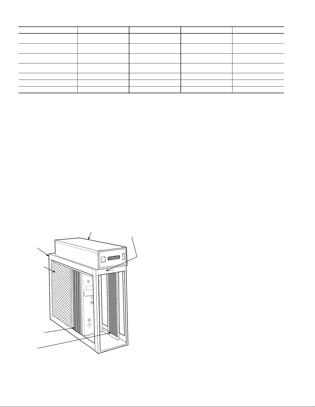
See Fig. 1 for a description of the electronic air cleaner.
Cabinet — The cabinet is constructed of heavy gage galva-
nized steel. Holes are provided in the cabinet for easy mounting
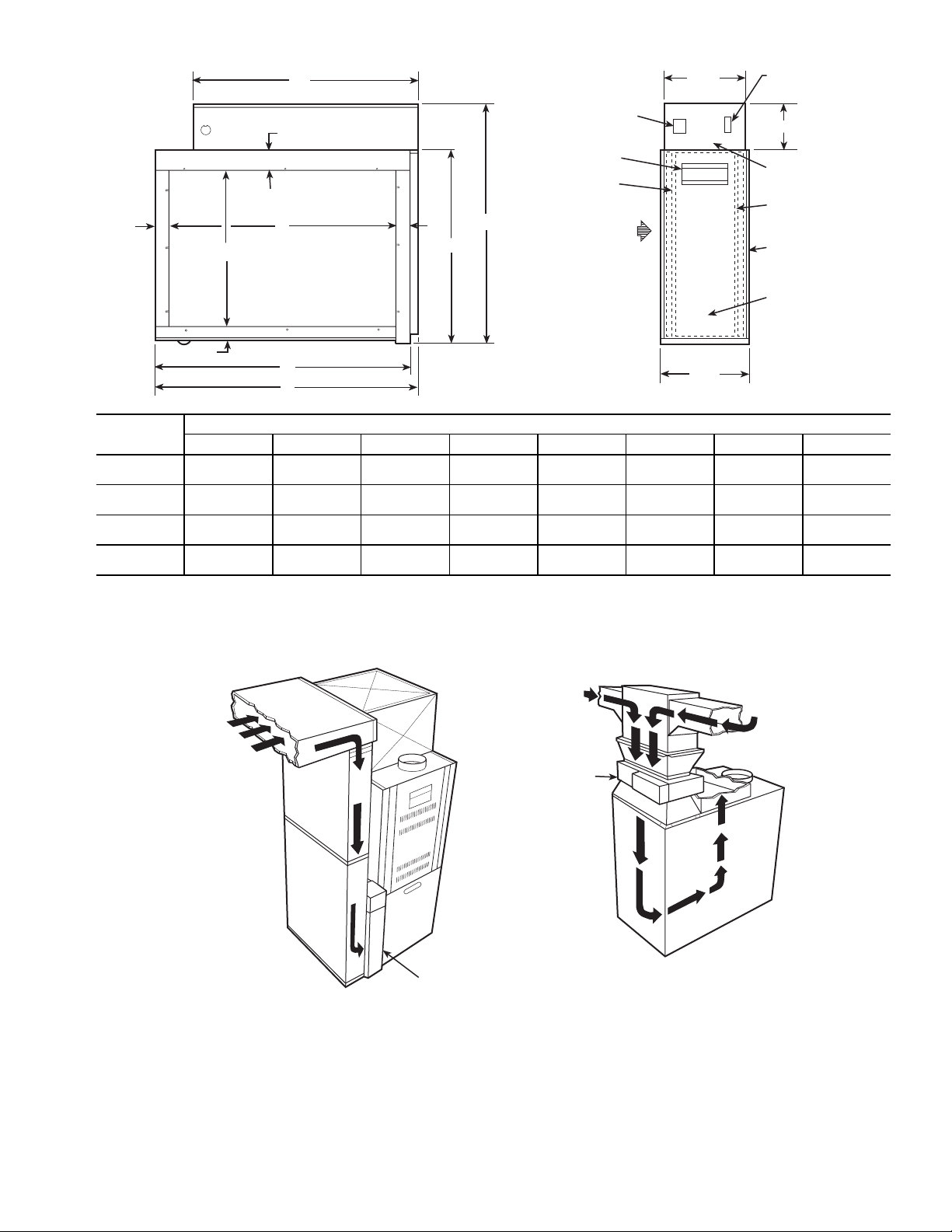
in the ductwork or air-handling equipment. See Fig. 2 for cabi-
net dimensions.
IMPORTANT: Read entire instructions before install-
ing the air cleaner.
Before beginning any installation or modification, be cer-
tain that the main line electrical disconnect switch is in the
OFF position. Electric shock could result. Tag disconnect
switch with suitable warning labels.
INSTALLATION,
OPERATION, AND
MAINTENANCE
INSTRUCTIONS
Residential Duct Mount
Electronic Air Cleaner
2
Table 1 — Specifications
Power Box — The removable power box contains the
power switch, performance indicator light, safety interlock
switch, high voltage power board, and air proving switch.
Air Proving Switch (APS) — An integrated air prov-
ing switch automatically cycles the electronic air cleaner on
and off with the furnace fan. The APS will detect airflow (fan
on) and energize the electronic air cleaner.
High Voltage Tray — The high voltage tray contains the
contacts and wires to supply high voltage to the collecting
cells.
Collecting Cells — The collecting cells consist of an
ionizing section and a plate section. The arrow on the cell must
point toward the furnace fan.
Prefilters — The prefilters are constructed from aluminum
mesh and prevent lint and other large particles from entering
the collecting cells.
Carbon Filters — The carbon filters are used to remove
odors. They are not washable and should be replaced every
six months. No more than 3 carbon filters should be used at the
same time.
INSTALLATION
Location — The electronic air cleaner must be installed in
the return air duct, as close to the blower compartment as possi-
ble. This location provides the most even airflow across the
collecting cells and allows the electronic air cleaner to keep the
system motor and blower clean. See Fig. 3. When choosing
location, there must be adequate room to wire the air cleaner
and remove prefilters, cells, and power box.
NOTE: Be sure to notify home owner not to install any device
within 2 ft from the top of the air cleaner after installation is
complete. Regular servicing of the electronic air cleaner is
required. A 2 ft clearance is required to remove filters for
cleaning.
INSTALLATION LOCATION WITH HUMIDIFIER — If a
separate humidifier is purchased, it should be installed in the
furnace warm air duct. However, a humidifier may be installed
in the return air duct without causing problems to the air clean-
er. Care must be taken to ensure that the humidifier does not
leak, as this may cause arcing at the electronic air cleaner and
mineral deposits on the collecting cells.
An atomizing-type humidifier should only be installed
downstream of the electronic air cleaner. If the atomizing-type
humidifier is installed upstream, high humidity, salts, and
minerals may decrease the efficiency of the collecting cells and
cause service problems.
If the atomizing-type humidifier must be installed upstream,
the following precautions should be taken:
1. Atomizing-type humidifier must be installed as far
from the electronic air cleaner as possible.
2. The collecting cells on the electronic air cleaner must
be washed frequently to prevent a mineral deposit
build up.
INSTALLATION LOCATION WITH AIR CONDI-
TIONER — Whenever possible, the electronic air cleaner
should be installed upstream of the cooling coil. This location
will clean the air before it reaches the evaporator coil.
Electronic Air Cleaner Installation — Perform the
following to install the electronic air cleaner:
1. Remove the existing furnace filter. Thoroughly clean
the blower compartment and ductwork where the air
cleaner is to be installed.
2. Open access door. Slide the prefilters and collecting
cells out of the cabinet.
3. Place cabinet in ductwork. Holes are provided to
attach cabinet to ductwork or equipment. If the adjoin-
ing ductwork is flanged, install the screws so that the
screw heads are inside the cabinet. This will help pre-
vent damage to prefilters and optional carbon filters
during removal for cleaning. Never put screws or
rivets into the removable power box.
PART NUMBER P102-12 P102-14A P102-14B P102-20
House Size Area < 2400 ft2
< 222.96 m2
< 3000 ft2
< 278.70 m2
2400-3000 ft2
222.96-278.70 m2
> 3000 ft2
> 278.70 m2
Airflow up to 1200 CFM
up to 2039 m3/hr
up to 1400 CFM
up to 2379 m3/hr
up to 1400 CFM
up to 2379 m3/hr
up to 2000 CFM
up to 3398 m3/hr
Duct Size 16 x 20 in.
405 x 510 mm
16 x 25 in.
405 x 635 mm
20 x 20 in.
510 x 510 mm
20 x 25 in.
510 x 635 mm
Unit Weight 28 lbs
12.9 kg
30 lbs
13.5 kg
33 lbs
15.3 kg
38 lbs
17.5 kg
Input Voltage 120 V 60 Hz 120 V 60 Hz 120 V 60 Hz 120 V 60 Hz
Power Consumption 30 Watts 30 Watts 30 Watts 30 Watts
Options Available Activated Carbon Filters Activated Carbon Filters Activated Carbon Filters Activated Carbon Filters
HIGH VOLTAGE
TRAY (HIDDEN)
CABINET
PREFILTERS
COLLECTING
CELLS
CARBON
FILTERS
POWER BOX
Fig. 1 — Electronic Air Cleaner
3
G
C
F
D
E
B
H
FA
F
20"
7 1/2"
COLLECTOR
CELLS
ACCESS DOOR
AIR PROVING
SWITCH
CARBON FILTERS
3 7/8"
PERFORMANCE
INDICATOR
(NORMALLY ON)
7 1/8"
POWER SWITCH
HANDLE
PREFILTERS
LEFT TO RIGHT
OR
RIGHT TO LEFT
AIR FLOW
RETURN AIR
RETURN AIR
ELECTRONIC
AIR CLEANER
RETURN AIR
ELECTRONIC
AIR CLEANER
RETURN AIR
Fig. 2 — Dimensions
HI BOY FURNACE LO BOY FURNACE
UNIT DIMENSIONS — in. (mm)
ABCDEFGH
P102-12 21
(530)
17
(435)
231/4
(590)
131/8
(335)
203/4
(530)
11/4
(30)
233/4
(605)
23/8
(60)
P102-14A 21
(530)
17
(435)
26
(660)
135/8
(345)
24
(610)
1
(25)
261/2
(675)
21/8
(55)
P102-14B 257/8
(660)
22
(560)
211/4
(540)
18
(460)
183/4
(475)
11/4
(30)
213/4
(550)
23/8
(60)
P102-20 257/8
(660)
22
(560)
26
(660)
18
(460)
231/2
(595)
11/4
(30)
261/2
(675)
23/8
(60)
NOTE: 22 in. (560 mm) clearance required for cleaning air cleaner. 6-in. (150 mm) clearance around power box for
removal.
Fig. 3 — Electronic Air Cleaner Installation Location
4
When the air duct does not fit the air cleaner opening,
a gradual transition is recommended to reduce air tur-
bulence through the air cleaner and to increase its effi-
ciency. There should not be more than 20 degrees of
expansion used on each side of the transition fitting.
Do not reduce ductwork to a smaller air cleaner or it
will increase the velocity of airflow.
4. If the air cleaner is installed adjacent to an elbow or
angle fitting, turning vanes are recommended to
improve air distribution across the collecting cells.
5. After electronic air cleaner has been secured, seal
seams airtight with duct tape or caulking to prevent
dust from entering the system.
6. Replace prefilters and collecting cells. Make sure
arrow on cell is pointing towards the fan. The cell han-
dle may need to be repositioned if the airflow is in a
different direction than the left to right set up. The
handle should face the door. Close access door.
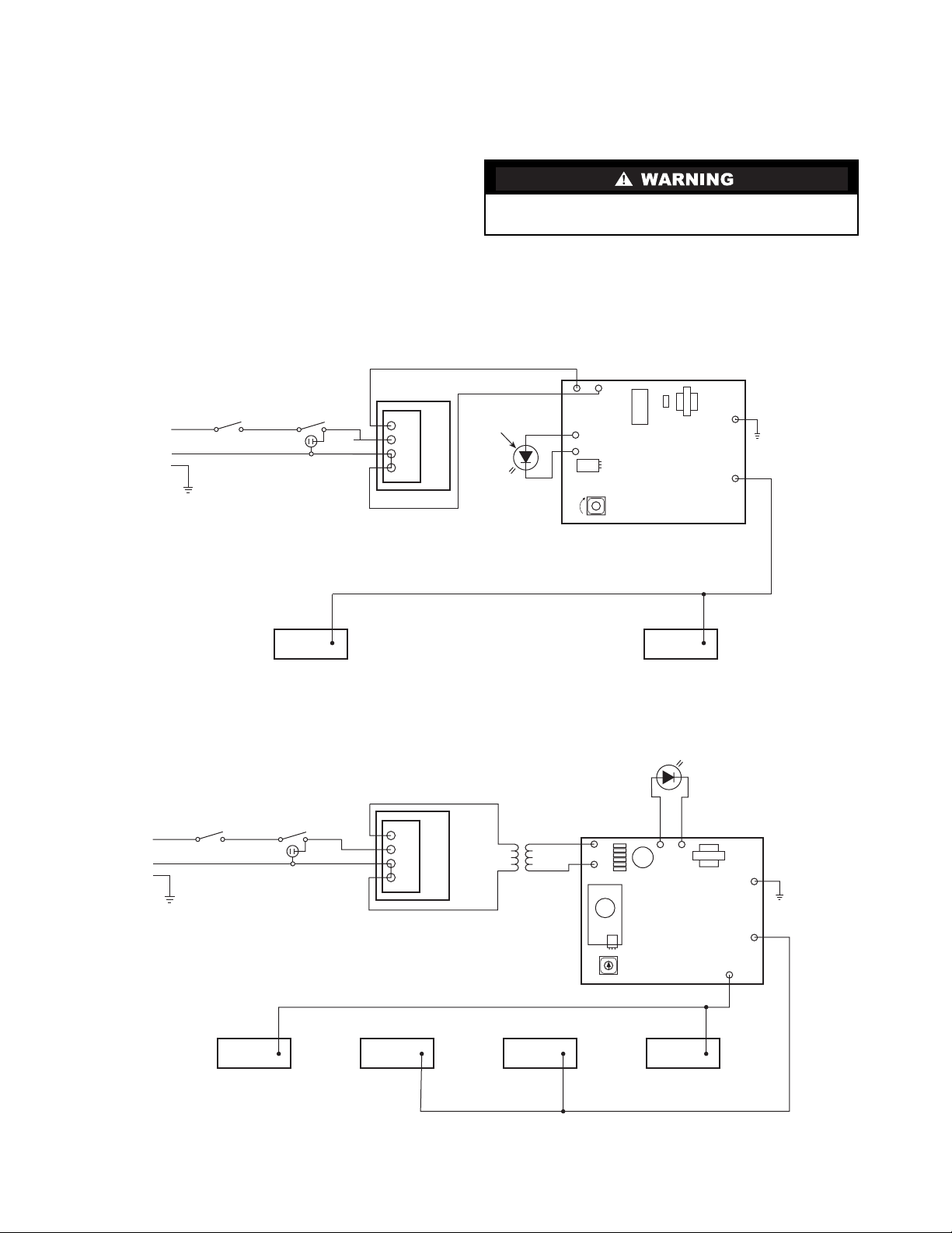
Wiring — Wiring should be performed by qualified person-
nel only. All wiring must comply with all applicable codes and
standards. The voltage of the power source must match the
voltage indicated on the electronic air cleaner. The electronic
air cleaner should operate ONLY when the fan is running.
Make sure the electronic air cleaner is properly grounded.
Wire the electronic air cleaner directly to the 120-v power
source. The APS will power the electronic air cleaner when
there is sufficient airflow to activate the sensor. See Fig. 4
and 5.
NOTE: The power switch will belit even if there is no airflow.
Electrical shock can cause injury or death. Be certain main
line disconnect switch is off before wiring.
T
12
6300-6600 VDC ON CONTACTS
POWER
SW2
INTERLOCK
SW1
GND
INPUT
PERFORMANCE
LIGHT
(NORMALLY ON)
120 VAC
LN
HV1
CLR
POWER
BOARD
H.V. ADJ.
617
(REV.01)
+
-
4
3
2
1
APS
AIR PROVING SWITCH
2V LED
P7 (RED)
P5 (BLK)
TR1
24V
HV2
HV1
BLK
BLK
CLR
CONTACTS 1 & 4 - 7200-7800 VDC
1234
H.V. ADJ.
CONTACTS 2 & 3 - 4800-5200 VDC
4
3
2
1
APS
AIR PROVING SWITCH
POWER
SW2
INTERLOCK
SW1
GND
PERFORMANCE
LIGHT
(NORMALLY ON)
INPUT
P3 (RED)
P4 (BLK)
2V LED
CLR
POWER
BOARD
618
(REV. 01)
Fig. 4 — Electronic Air Cleaner Wiring — P102-12 and P102-14A Units
Fig. 5 — Electronic Air Cleaner Wiring — P102-14B and P102-20 Units
NOTE: If APS is not
used, Wires 1 & 2
and 3 & 4 are con-
nected together.
NOTE: On the 220-240 volt version of the 16x20 and
the 16x25, the 618 power board is used. Only the HV1
output terminal of the power board is used.
NOTE: If the APS is not
used, Wires 1 & 2 and 3 & 4
are connected together.

5
SYSTEM CHECK
Perform the following system check before operation.
1. Make sure all electronic air filter components are in
place and that access door is closed.
2. Turn electronic air cleaner power switch to ON.
Ensure system blower fan is operating. Both power
switch light and the performance indicator light should
be lit. The power switch light indicates the electronic
air cleaner has unit voltage. The performance indicator
light shows that the electronic air cleaner is operating.
NOTE: There may be some arcing or snapping sounds from
the cells or some odor of ozone. This is normal when the unit is
new. In about 2 weeks, as the sharp edges of the collecting
cells become smoother, the arcing and odor will disappear.
OPERATION
The electronic air cleaner will run as long as there is
airflow through the ducts. The electronic air cleaner will not
run if the blower fan is off.
For proper operation of the electronic air cleaner, these steps
should be followed:
• run your heating/cooling system fan continuously and on
low speed if available
• remove furniture or carpets which block return air grilles
throughout your house, so that air moves freely to the
furnace
• check for proper operation of the blower fan on the
furnace
• ensure that the prefilters are cleaned on a regular basis.
Ozone — The electronic air cleaner emits less than
0.005 ppm of ozone. Ozone may be noticeable in ex-
tremely dry environments and can be prevented with proper
humidification.
Dust — After installation of the electronic air cleaner, you
may notice some white dust on table tops and shelves. Most
heavy particles (such as lint) settle quickly and do not get
filtered through the electronic air cleaner. To reduce lint and
dust, use continuous fan operation and keep return vents
unrestricted to create an efficient airflow.
Lint dust, which is too heavy to remain airborne, will be
cleaner as the darker, staining particles have been removed by
the electronic air cleaner. Lint will be more noticeable against
dark furnishings. The electronic air cleaner does not produce
more lint or dust.
MAINTENANCE
It is very important that the scheduled maintenance be done
by the home owner. If cells and filters are not cleaned and
changed on a regular basis, the electronic air cleaner will not
operate effectively.
Cell and Prefilter Cleaning — The collecting cells
and prefilters must be cleaned on a regular basis for the air
cleaner to function at its peak efficiency. The frequency of
cleaning will vary from one house to another. On average, the
cells should be cleaned every 3 months. To clean cells:
1. Remove door, cells, and prefilters.
2. Place cells in a laundry tub. Rinse cells with hot water
and spray completely with a non-chlorine, noncorro-
sive, non-abrasive liquid household detergent. (DAX
detergent is recommended.) Allow detergent to run
down both sides of plates and ionizing wires. Let stand
for 5 minutes.
3. 3. Rinse cells with hot water (maximum 120 F [49 C]).
4. If dirt remains, let cells soak in solution of DAX deter-
gent and water for 30 minutes.
5. Tilt cells on a 45 degree angle on their short side and
allow to dry completely (approximately 8 to 10 hours).
A hair dryer may be used to speed up drying time.
6. Wash prefilters. Do not wash in the same water as col-
lecting cells. Spray prefilters with DAX detergent,
rinse, and let dry.
7. Place cells and prefilters back into cabinet. Close
access door and turn unit on. If the performance indi-
cator light does not come on or arcing occurs, turn the
electronic air cleaner off and allow the furnace fan to
dry the cells completely.
Carbon Filter Replacement — If the air cleaner has
optional carbon filters, they should be replaced every 3 to
6 months. Carbon filters remove odors from the air. Filters are
NOT washable. To replace filters, perform the following:
1. Turn off power switch on electronic air cleaner.
2. Turn off furnace fan.
3. Open electronic air cleaner access door.
4. Remove cells from electronic air cleaner.
5. Pull out the used carbon filters. If the carbon filters do
not slide out easily, tilt them at a 45-degree angle and
they will fall out.
6. Put new carbon filters into electronic air cleaner. Space
filters evenly across face of air cleaner. Never put
more than 3 carbon filters in the electronic air cleaner
as this may cause a problem with airflow.
7. Reinstall cells. Close access door.
8. Turn on power to furnace fan and electronic air
cleaner.
SERVICE
Testing Air Proving Switch (APS) — The APS sen-
sor must protrude through the plastic bushing to work effec-
tively. The sensor is very sensitive and operation may be
affected by cold basement temperatures, an air exchanger, or a
fresh air duct connected to the cold air return just upstream of
the electronic air cleaner.
The APS uses a Triac in its output circuit which affects the
voltage sine wave. Using a regular digital voltmeter will give a
false reading. To check the output from the APS, use a true
RMS (root mean square) meter to measure the output at termi-
nals 1 and 4 of the APS. The output should be between 105 and
115 VAC, depending on the airflow across the sensor.
Make sure to turn electronic air cleaner off before perform-
ing any maintenance or removing any components.
Damage to cells may occur if improperly handled or
washed. Do not wash cells in a dishwasher. Never use any
object to clean between the cell plates as this may cause
damage to plates or ionizing wires. Never place cell in
oven to dry. The edges of the cell may be sharp — handle
with care.
Electronic air cleaners use high voltage. Use extreme
caution when performing service on electronic air cleaner.
Only trained personnel should perform service. Electric
shock can cause injury or death.

6
A neon lamp may be used to test the output of the APS.
Place the leads of the lamp across terminals 1 and 4 of the APS,
or across the 120 v input of the single output power board. If
the lamp lights, the voltage is sufficient for operation.
When the electronic air cleaner is turned on without air-
flow, the APS sensor heats up and, after 30 seconds, opens the
circuit to turn off the power board. When the fan starts up (the
sensor is cooled), the circuit will close, the power board is
turned on, and the performance light will come on.
The light on the power switch will be lit even when the APS
is open.
If the power board fails to come on with the blower on,
check that the sensor is properly set down, through the plastic
bushing, in front of the power box. To check the APS for prop-
er operation, turn the unit on and activate. The power board
should come on immediately, and then turn off in 30 seconds as
the sensor heats up. To check sensor, blow directly on it lightly.
This should activate the power board within 10 seconds.
Service the sensor carefully; the sensor leads are 120 V.
Replacing an Air Proving Switch (APS) — Before
replacing the APS, turn off the power to the electronic air clean-
er. Perform the following procedure to replace the APS:
1. Disconnect wiring from terminals 1, 2, 3, and 4 on the
APS. See Fig. 4 and 5.
2. Release circuit board from plastic spacers by pinching
end of spacer and pulling board out.
3. Install new APS on plastic spacers. Ensure sensor pro-
trudes slightly through plastic bushing.
4. Connect wiring to terminals on APS. See Fig. 4 and 5.
Wiring from power source is connected to terminals 2
and 3. Wiring to power board is connected to termi-
nals 1 and 4.
5. Test the new APS. See procedure on page 5.
Testing for High Voltage at Power Board — A
high voltage meter capable of measuring up to 10,000 VDC is
required to test the voltage. Perform the following procedure to
test for high voltage at the electronic air cleaner power board:
1. The air cleaner should be on with the door closed. The
unit fan should be running. The electronic air cleaner
should be on at least 5 minutes to allow voltage to
stabilize.
2. Remove cover from power box.
3. Connect the ground of the high voltage meter to an
unpainted surface in the power box.
4. Check terminals HV1 and HV2 (where applicable) on
the power board to determine if voltage is present.
5. If no voltage present, remove both cells from the air
cleaner and replace door.
a. Check the voltage at HV1 and HV2 (where appli-
cable) again.
b. If voltage is present, the problem is with one of the
cells or the copper contact on the high voltage tray.
c. With a flashlight, look into the cabinet to check
condition of the copper contacts.
d. If the contacts are not bent, replace one cell and
retest voltage. If cell is OK, test the other cell. If
the problem is with a cell, see troubleshooting
guide.
e. Check the APS to make sure that it is functioning
correctly.
f. Check the transformer to make sure power is being
supplied to the electronic air cleaner.
6. If there is voltage present but the performance light
does not come on, replace light.
7. High voltage can be adjusted with high voltage poten-
tiometer if required.
Replacing Performance Light — Before replac-
ing performance light, turn off power to the electronic air
cleaner at the source. Perform the following procedure:
1. Remove the power box cover.
2. Disconnect the performance light wiring connected to
the LED terminals on the power board.
3. Push the light out through the front of the power box.
4. Push the new light into the power box.
5. Connect the wiring to the LED terminals on the power
board. See Fig. 4 and 5.
6. Replace cover.
7. Return power to electronic air cleaner. Test light.
Replacing a Power Board — Before replacing pow-
er board, turn off power to the electronic air cleaner at the
source. Perform the following procedure:
1. Remove the power box cover.
2. Disconnect wiring from the LED, HV1, and 120 VAC
power board terminals (P102-12 and P102-14A) or
LED, HV1, HV2, and 24 v terminals (P102-14B and
P102-20) and ground. See Fig. 4 and 5.
3. Remove the hex nut from the power board.
4. Release the power board from the three plastic board
spacers by pinching the end of the spacers and pulling
the board out.
5. Push new board onto spacers. Make sure spacers click
into place to hold down board.
6. Screw on the hex nut saved from Step 3. Ensure the
star washer is in place over the steel spacer for proper
grounding.
7. Reconnect wiring to LED, HV1, and 120 VAC (P102-
12 and P102-14A) terminals or LED, HV1, HV2, and
24 v terminals (P102-14B and P102-20) and ground on
the new power board.
8. Replace power box cover.
9. Return power to electronic air cleaner. Test power
board.
NOTE: Although the power board has been set before ship-
ping, it may be necessary to reset the voltage to the correct load
for optimum efficiency. Refer to Testing Voltage of Power
Board section for more information.
Testing the 24-V Transformer (P102-14B and
P102-20 Only) — To test the 24-v transformer, perform
the following procedure:
1. The electronic air cleaner should be on. The unit fan
should be running. The electronic air cleaner door
should be closed.
2. Remove power box cover.
3. Disconnect the leads of the 24-v transformer from the
power board. See Fig. 5.
4. Measure voltage across leads with a voltmeter. Voltage
should read 24 to 27 VAC.
5. If no voltage present, check the operation of the APS.
6. Before replacing transformer, check the resistance of
the power board input. Input should read above
40 Kohm. If resistance is below 40 Kohm, the power
board may be the cause of the transformer failure.
7. Reconnect leads to power board.
8. Replace power box cover.

7
Replacing the 24-V Transformer (P102-14B
and P102-20 Only) — Before replacing 24-v transform-
er, turn off power to the electronic air cleaner at the source.
Perform the following procedure:
1. Remove power box cover.
2. Disconnect the secondary leads from the transformer
to the 24 v terminals on the power board. See Fig. 5.
3. Cut the primary leads (to the APS) close to the
transformer.
4. Remove the two hex head nuts from the transformer
studs.
5. Remove transformer.
6. Place new transformer over studs and re-install two
hex head nuts to lock into place.
7. Connect secondary leads (white) to the 24 v terminals
on the power board.
8. Wire nut primary leads from APS (cut in Step 3) to pri-
mary leads from transformer.
9. Replace power box cover.
10. Turn on power to electronic air cleaner and test.
Testing Voltage of Power Board — Voltage on the
power board may drop below required level when installation
area is too damp, too cold, or if there is a leakage of water from
a humidifier. Voltage on power board may be too high when
installation area is too dry or too hot. By adjusting the HV
ADV potentiometer, the voltage can be set to optimum level. A
high voltage meter capable of measuring 10,000 VDC is re-
quired. To test and adjust voltage level, perform the following
procedure:
1. Turn the electronic air cleaner off.
2. Remove the power box cover.
3. Connect the ground of the high voltage meter to an
unpainted surface in the power box.
4. Turn on the electronic air cleaner and wait 5 minutes
before checking voltages to allow voltages on cells to
stabilize.
5. Measure the voltages at HV1 and HV2 (where applica-
ble) on the power board. See Fig. 6.
6. Adjust the HV ADV potentiometer until the voltage
reading matches the voltage in Table 2.
7. Turn off the electronic air cleaner.
8. Remove the high voltage meter.
9. Replace the power box cover.
10. Turn on electronic air cleaner.
Table 2 — Power Board Voltage Settings
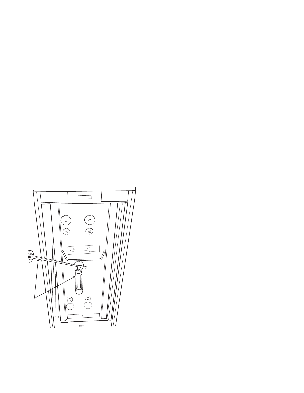
TESTING VOLTAGE AT CELL — To test the voltage at the
cell, perform the following procedure:
1. Open the door to the air cleaner. Air cleaner will shut
off.
2. Insert a thin shafted screwdriver 2 to 3 inches into the
hole in the round end plate insulator. See Fig. 7.
3. Attach the ground of the high voltage meter on to a
grounded area of the cell.
4. Place the tip of the high voltage probe on the shaft of
the screwdriver. Press down the safety interlock.
Power to electronic air cleaner will come on.
UNIT MAXIMUM VOLTAGES
ON PLATES (K VDC)
MAXIMUM VOLTAGE ON
IONIZER (K VDC)
P102-12,
P102-14A 6.2 - 6.5 (HV1) 6.2 - 6.5 (HV1)
P102-14B,
P102-20 4.8 - 5.2 (HV1) 7.2 - 7.8 (HV2)
HIGH VOLTAGE
PROBE GROUND
PROBE
SAFETY
INTERLOCK
PROBE
GROUNDED
AREA
SCREWDRIVER
Fig. 6 — Testing Voltage at Power Board
Fig. 7 — Testing Voltage at Cell
8
5. Wait until the voltage stabilizes then take a reading.
Adjust the HV ADV potentiometer until the voltage
reading matches the voltage in Table 2. If the voltage
fails to stabilize or jumps up and down by more than
100 v, there may be a bad contact in the cell or a bad
contact between the cell contacts and the high voltage
contacts on the contact tray.
6. Let up on the safety interlock. Remove high voltage
meter.
7. Remove screwdriver and close access door.
SET APPROXIMATE VOLTAGE WITHOUT HIGH
VOLTAGE METER — A high voltage meter should be used.
If one is not available, this method can be used. This will only
set an approximate voltage. After using this method, the
voltage should be reset with a high voltage meter as soon as
possible.
1. Remove power box cover.
2. Turn the HV ADV potentiometer fully clockwise.
Electronic air cleaner may arc or snap at this point.
3. Turn the HV ADV potentiometer counterclockwise
slowly until the arcing and snapping stops.
4. Replace power box cover.
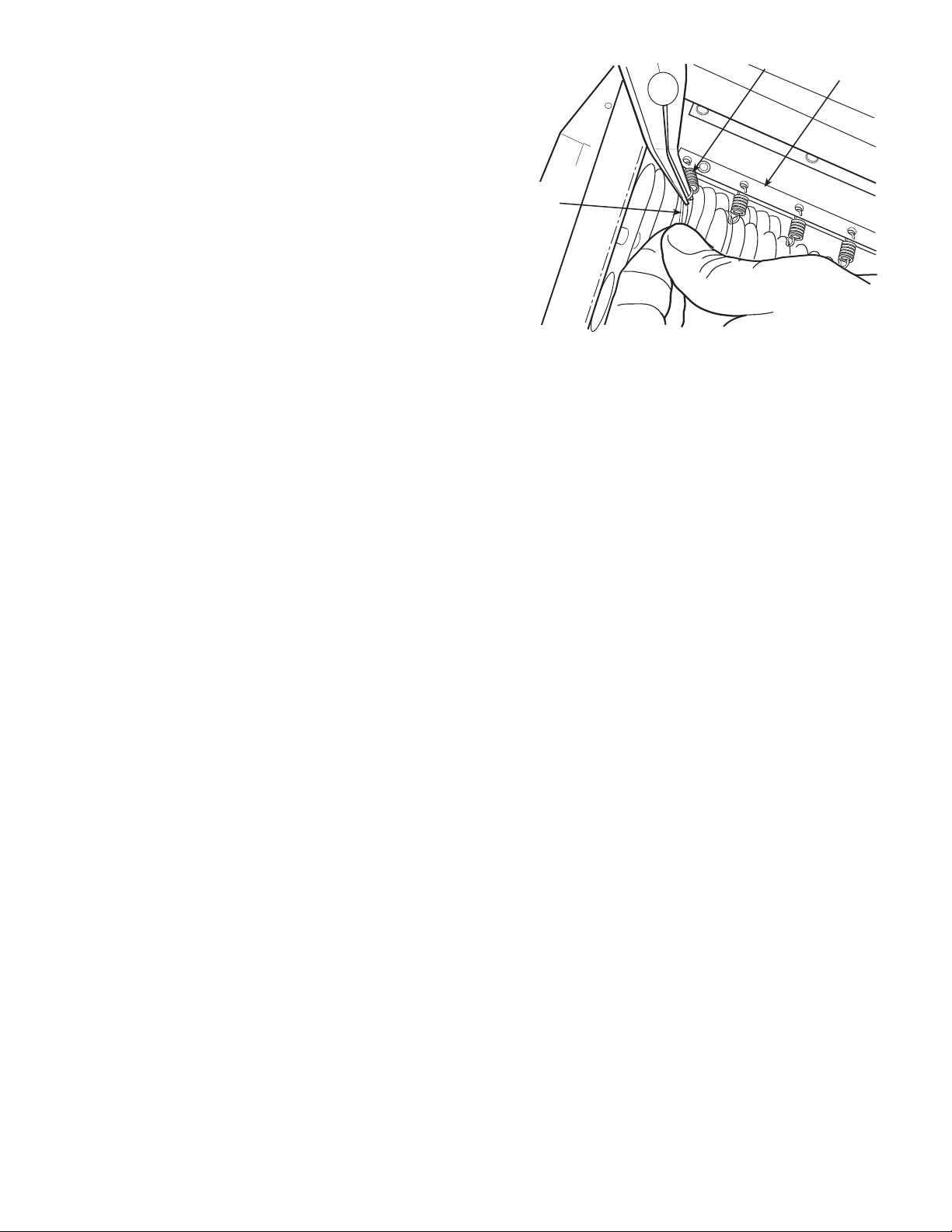
Testing Cell for Bad Contacts — To test a cell for
bad contacts, perform the following procedure:
1. Open access door to air cleaner.
2. Place a screwdriver between plates of the cell, or place
a small screwdriver into the hole in the end plate insu-
lator and short with another screwdriver to cell end
plate. See Fig. 8.
3. Press safety interlock switch to start electronic air
cleaner. There should be an initial snap when the plates
are shorted, then no sound. If a hissing occurs, then
there is a bad contact. Look along the top of the cell,
with the short still in place. If there is a small arc
between the cell top and copper contact, then that is
the bad contact. Pull cell out and gently pull copper
contact down.
If an arc is not seen and there is a bad contact, then the
problem may be the internal contact of the cell. With
an ohmmeter, check continuity between the top disc
contact and the first plate. The reading should be close
to 0 ohms. If not, bend the contact to touch the plate.
On dual voltage units (three disc contacts), there
are two internal contacts, one on each side. Test each
contact.
4. Let up on safety interlock.
5. Remove screwdrivers.
6. Close access door.
Removing Power Box — To remove the power box,
perform the following procedure:
1. Turn the main furnace switch off or disconnect the
power source.
2. Remove the power box cover.
3. Disconnect the source wires to the electronic air
cleaner. Cap off the wires so the furnace can still be
operated.
4. Disconnect high voltage leads from power board.
5. Remove three nuts holding the power box to the
cabinet.
Removal of High Voltage Contact Tray — To re-
move the high voltage contact tray, perform the following
procedure:
1. Turn off power to electronic air cleaner.
2. Remove cells, prefilters, and carbon filters from elec-
tronic air cleaner.
3. Remove the high voltage wires from the power board.
4. Remove the 4 screws that hold the high voltage contact
tray in place. Two screws are located at the top, rear
section of the cabinet. The other two screws are
located in the front, top section of the cabinet (behind
the door). Lower the tray into the cabinet area while
feeding the high voltage wires down through the plas-
tic wire bushing. The wire with clear or no sleeving is
connected to terminal HV1 on the power board. The
wire with black sleeving is connected to terminal HV2
on the power board.
5. To remove the tray, slide the tray forward and release
the tab at the rear end of the cabinet.
6. To reinstall high voltage contact tray, reverse above
procedure.
SCREWDRIVER
Fig. 8 — Bad Contact Test
9
Replacing a Tungsten Ionizing Wire — Replace-
ment wires are cut to the correct length and have eyelets at each
end for easy replacement. To replace an ionizing wire, perform
the following procedure:
1. Turn off power to electronic air cleaner.
2. Remove cell from electronic air cleaner.
3. Remove all parts of broken wire, as well as spring and
S-hook. If necessary, cell may be used temporarily
with one wire missing until a replacement is received.
4. Using needle nose pliers, place spring hook in the hole
of the ionizing bar near cell top.
5. Place eyelet of wire over the S-hook and place S-hook
into hole on ionizing bar on other side of cell. Keep
wire tight to ensure S-hook remains in hole.
6. Using the needle nose pliers, grab the end of the spring
and stretch towards loop in wire. Place eyelet in wire
over spring hook and release spring. See Fig. 9.
7. Install cell in electronic air cleaner.
8. Return power to electronic air cleaner.
9. Test cell for proper operation.
WIRE
IONIZING
BAR
SPRING
Fig. 9 — Replacing an Ionizing Wire

10
TROUBLESHOOTING
Refer to Table 3 for troubleshooting information.
Table 3 — Troubleshooting
PROBLEM PROBABLE CAUSE REMEDY
Unit does not function correctly.
Power light and performance
indicator light are off.
Fan is not on. Turn furnace fan on.
Wiring improperly connected. Check wiring.
Defective power switch. Check power switch for continuity with multimeter. Replace
if defective.
Defective safety interlock. Remove door and press safety interlock with a screwdriver.
If lights come on, bend interlock lever towards front and
close door.
Power (120 v) is not provided to device. Check power wiring with multimeter.
Power light is off and per-
formance indicator light is on.
Defective power light. Replace power switch.
Unit does not function correctly.
Power light is on and per-
formance indicator light is off.
Short in cells. Due to:
1. Broken ionizing wire(s).
2. Large particles wedged between cell plates.
3. Cells washed recently and are still wet.
4. Round end plate insulator is burnt or melted.
5. Cell plates are bent.
1. Remove wire or wire fragments, spring and S-hook.
Replace.
2. Shake large particles out or wash cell.
3. Allow cells to dry completely.
4. Replace end plate insulator.
5. Straighten plates with pliers.
Defective performance indicator light. Determine whether high voltage is present by testing power
box. If present, replace indicator light.
Defective power board. Adjust high voltage potentiometer on power board clock-
wise. If high voltage is not present, replace power board.
Air proving switch sensor is burnt out. Remove power box and connect with 120 v. Lightly blow on
air switch at the bottom of power box. If light does not come
on, replace switch.
Off board 24-v transformer is not working. Verify output of transformer. Replace if necessary.
Cell makes loud hissing noise or
causes radio interference.
Internal cell contacts are not touching plates. Test contact and repair.
Copper contacts on high voltage tray not mak-
ing good connection on cell.
With needle-nose pliers, gently pull contacts down or
replace contacts.
Cells arcing excessively (power
light and performance indicator
light on)
Cells wet from washing. Allow cells to dry completely.
Particle lodged in cell or broken ionizing wire. Wash cell. Shake particle out of cell. Replace wire, if
necessary.
Ducts were not cleaned prior to installation of
electronic air cleaner.
Clean ducts.
Cell plates are bent. Remove cells and adjust to original spacing using needle
nose pliers.
Voltage is too high. Adjust high voltage potentiometer on power board
counterclockwise.
Humidifier (if installed) is leaking water on air
cleaner.
Repair humidifier. If possible, move humidifier to different
location.
Cells arcing excessively at top of
cell near copper contacts (power
light and performance indicator
light on)
Contacts on high voltage tray are broken or
bent upward.
If possible, pull down contacts with needle nose pliers or
remove high voltage tray and replace contacts.
Cells not collecting dirt (power
light and performance indicator
light on)
Arrow on cell(s) not pointing towards fan blower. Reposition cells.
Furnace fan is on ‘‘Automatic’’ setting (air
cleaner not on continuously)
Use ‘‘Fan On’’ furnace fan setting for continuous fan
operation.
Not enough voltage on collecting cells. Adjust high voltage potentiometer clockwise on power
board.
Ozone odor Cell plates are bent. Straighten with needle nose pliers.
Loose or broken ionizing wires. Replace wires.
Dirty cells. Wash cells.
Electronic air cleaner is on when system fan is
not running. Air switch not activated, or elec-
tronic air cleaner wired incorrectly.
Check operation and wiring of air switch and electronic air
cleaner.
Incoming voltage is higher than 120 v. Adjust high voltage potentiometer counterclockwise on
power board.
Air cleaner is oversized for house. Not enough
airflow to cover surface area of cells.
Use correct size of electronic air cleaner.
Home is extremely dry. Repair or install central humidifier.
More dust after installation than
before
Lint dust too heavy to remain airborne. Keep fan running continuously. Ensure that return air grilles
are not obstructed.
Gaps around electronic air cleaner. Seal or use duct tape around electronic air cleaner cabinet.

11
ELECTRONIC AIR CLEANER
LIMITED FIVE-YEAR WARRANTY
FIVE-YEAR WARRANTY — This CARRIER CORPORATION product is warranted to be free from defects in
material and workmanship under normal use and maintenance for a period of five years from the date of original
installation. A new or remanufactured part to replace the defective part will be provided without charge for the
part itself, through a qualified servicing CARRIER CORPORATION dealer or service, PROVIDED the defective
part is returned to our distributor. The replacement part assumes the unused portion of the warranty.
THIS WARRANTY DOES NOT INCLUDE ANY ADDITIONAL LABOR ALLOWANCE OR OTHER COSTS,
incurred for diagnosis, repairing, removing, installing, shipping, servicing, or handling of either defective parts or
replacement parts. SUCH COSTS MAY BE COVERED BY a separate warranty provided by the installer.
LIMITATIONS OF WARRANTIES — ALL IMPLIED WARRANTIES (INCLUDING IMPLIED WARRANTIES OF
MERCHANTABILITY) ARE HEREBY LIMITED IN DURATION TO THE PERIOD FOR WHICH THE LIMITED
WARRANTY IS GIVEN. THE EXPRESSED WARRANTIES MADE IN THIS WARRANTY ARE EXCLUSIVE AND
MAY NOT BE ALTERED, ENLARGED, OR CHANGED BY ANY DISTRIBUTOR, DEALER, OR OTHER PERSON
WHATSOEVER.
CARRIER WILL NOT BE RESPONSIBLE FOR:
1. Normal maintenance as outlined in the installation and servicing instructions or owners manual including
cleaning and/or replacement of filters, media or electronic cells.
2. Damage or repairs required as a consequence of faulty installation or application by others.
3. Failure to start due to voltage conditions, blown fuses, open circuit breakers or other damages due to the inad-
equacy or interruption of electrical service.
4. Damage or repairs needed as a consequence of any misapplication, abuse, improper servicing, unauthorized
alteration, or improper operations.
5. Damage as a result of floods, winds, fires, lightning, accidents, corrosive atmosphere, or other conditions
beyond the control of CARRIER CORPORATION.
6. Parts not supplied or designated by CARRIER CORPORATION.
7. CARRIER CORPORATION products installed outside the continental U.S.A., Alaska, Hawaii, and Canada.
8. ANY SPECIAL INDIRECT OR CONSEQUENTIAL PROPERTY OR COMMERCIAL DAMAGE OF ANY
NATURE WHATSOEVER. Some states do not allow the exclusion of incidental or consequential damages, so
the above limitation may not apply to you.
________________________________________________________________________________________
Model No. Unit Serial No.
_______________________________________________________________________________________
Date of Installation Installed by
_______________________________________________________________________________________
Name of Owner Address of Installation
_______________________________________________________________________________________

Manufacturer reserves the right to
discontinue, or change at any time,
specifications or designs without notice
and without incurring obligations.
REPLACEMENT COMPONENTS DIVISION LITERATURE NUMBER P102-2SI
© CARRIER CORPORATION 2002 3/02 REPLACES: EAC-50SI
PRINTED IN U.S.A. CATALOG NO. 570-476
Your Assurance of Quality
ALL Totaline products are backed by Carrier Corporation,
the world’s largest manufacturer of air conditioning,
heating, and refrigeration products.
This manual suits for next models
3
Table of contents
Other TOTALINE Air Cleaner manuals

TOTALINE
TOTALINE P103-R1700G User manual

TOTALINE
TOTALINE P103-RRUVL-012 User manual

TOTALINE
TOTALINE P103-QUATTRO User manual

TOTALINE
TOTALINE Star CG1000 Series User manual

TOTALINE
TOTALINE P102-BB14A Manual

TOTALINE
TOTALINE 1300 Series Manual

TOTALINE
TOTALINE Gold P102-350 User manual

TOTALINE
TOTALINE P102-400DM User manual
Popular Air Cleaner manuals by other brands

MANN+HUMMEL
MANN+HUMMEL OurAir SQ 500 Original operating manual

Honeywell
Honeywell F58F owner's guide

PremierOne
PremierOne MUV7-100TR Installation & maintenance instructions

Samsung
Samsung AX40R3030WM user manual

Aztech
Aztech AAP4660 Easy start guide

Reven
Reven X-CYCLONE RJ-1 Operating and maintenance instructions


