TOTALINE 1300 Series Manual

Manufacturer reserves the right to
discontinue, or change at any time,
specifications or designs without notice
and without incurring obligations.
REPLACEMENT COMPONENTS DIVISION
© CARRIER CORPORATION 2001 12/01 LITERATURE NUMBER P103-4SI
PRINTED IN U.S.A. CATALOG NUMBER 570-470
IF YOU NEED HELP call toll free: 1-800-565-5326
CONTENTS
SAFETY CONSIDERATIONS . . . . . . . . . . . . . . . . . . . . . . 1
PACKAGE USAGE . . . . . . . . . . . . . . . . . . . . . . . . . . . . . . . . 1
GENERAL . . . . . . . . . . . . . . . . . . . . . . . . . . . . . . . . . . . . . . . . 1
COMPONENTS . . . . . . . . . . . . . . . . . . . . . . . . . . . . . . . . . . . 2
Frames with Outer Screens . . . . . . . . . . . . . . . . . . . . . . 2
Collecting Pads . . . . . . . . . . . . . . . . . . . . . . . . . . . . . . . . . . 2
Charging Bar. . . . . . . . . . . . . . . . . . . . . . . . . . . . . . . . . . . . . 2
High Voltage Power Supply Box . . . . . . . . . . . . . . . . . . 2
INSTALLATION . . . . . . . . . . . . . . . . . . . . . . . . . . . . . . . . . .2,3
Location . . . . . . . . . . . . . . . . . . . . . . . . . . . . . . . . . . . . . . . . . 2
Electronic Air Cleaner Installation. . . . . . . . . . . . . . . . 3
OPERATION. . . . . . . . . . . . . . . . . . . . . . . . . . . . . . . . . . . . . . 3
MAINTENANCE . . . . . . . . . . . . . . . . . . . . . . . . . . . . . . . . 3-5
Collecting Pad Replacement . . . . . . . . . . . . . . . . . . . . . 3
TROUBLESHOOTING. . . . . . . . . . . . . . . . . . . . . . . . . . . . . 5
SAFETY CONSIDERATIONS
Read and follow manufacturer instructions carefully. Im-
proper installation may damage media air cleaner.
Recognize safety information. This is the safety alert
symbol . When the safety alert symbol is present on equip-
ment or in the instruction manual, be alert to the potential for
personal injury.
Understand the signal words DANGER, WARNING, and
CAUTION. These words are used with the safety alert symbol.
DANGER identifies the most serious hazards which will result
in severe personal injury or death. WARNING signifies a haz-
ard which could result in personal injury or death. CAUTION
is used to identify unsafe practices which would result in minor
personal injury or property damage.
Installation and servicing of air-conditioning equipment can
be hazardous due to system pressure and electrical compo-
nents. Only trained and qualified service personnel should
install, repair, or service air-conditioning equipment.
Untrained personnel can perform the basic maintenance
functions of replacing collecting pads. All other operations
should be performed by trained service personnel. When work-
ing on air-conditioning equipment, observe precautions in the
literature, tags and labels attached to the unit, and other safety
precautions that may apply.
Follow all safety codes. Wear safety glasses and work
gloves.
PACKAGE USAGE
GENERAL
The electronic air cleaner is designed to remove atmospher-
ic and household dust, pollen, mold spores, bacteria, fungi,
insecticide dust, animal dander, coal dust, mites, cooking
smoke and grease, tobacco smoke, and other particles down to
sub-micron levels.
The electronic air cleaner is installed in the furnace filter
rack where a filter would normally be placed. It is designed to
be installed in a 1-in. filter track. Many sizes are available to fit
in different size air ducts.
Airborne pollutants are carried through the return air ducts
of the heating/cooling system to the electronic air cleaner. The
collecting pads of the electronic air cleaner utilize electronic
polarization and ionization to create high filtration efficiencies.
The particles are captured by the collecting pads. The 1-in.
design protects HVAC equipment and their energy efficiencies
due to the electronic air cleaner’s low static pressure.
Regular maintenance (replacement or cleaning of collecting
pads) is required by the home owner.
IMPORTANT: Read entire instructions before
installing the electronic air cleaner.
Before beginning any installation or modification, be cer-
tain that the main line electrical disconnect switch is in the
OFF position. Electric shock could result. Tag disconnect
switch with suitable warning labels.
PART NUMBER SIZE (in.)
P130-1224C 12 x 24
P130-1424C 14 x 24
P130-1425C 14 x 25
P130-1430C 14 x 30
P130-1520C 15 x 20
P130-1620C 16 x 20
P130-1624C 16 x 24
P130-1625C 16 x 25
P130-1820C 18 x 20
P130-2020C 20 x 20
P130-2024C 20 x 24
P130-2025C 20 x 25
P130-2424C 24 x 24
P130-2425C 24 x 25
P130-2430C 24 x 30
INSTALLATION,
OPERATION, AND
MAINTENANCE
INSTRUCTIONS
1300 Series
Electronic Air Cleaner

2
COMPONENTS
See Fig. 1 for a description of the electronic air cleaner.
Frames with Outer Screens — The frame is made
up of two sides. An optional key is supplied with the frame and
may be used to lock and unlock the corner fasteners. The key is
located over the top of the outlet and LED lights. The outer
screens may be vacuumed or washed when dirty.
Collecting Pads — The collecting pads are used to filter
the air. One of the collecting pads will contain carbon fibers
which are used to ionize and polarize the pads. The pads cannot
be washed or vacuumed and must be replaced when dirty.
Charging Bar — The charging bar is laid across the top of
the collecting pad with the carbon fibers and must be in contact
with the carbon fibers on the pad. The charging bar is energized
by the high voltage power supply box.
High Voltage Power Supply Box — The high volt-
age power supply box provides power to the electronic air
cleaner. A 24-V supply cord and jack is provided for wiring to
a 24-V power source.
INSTALLATION
Location — If a filter rack exists, then the electronic air
cleaner should be installed in the filter rack. Note the dimen-
sions of the filter rack and order the appropriate sized electron-
ic air cleaner to fit the rack.
If a filter rack does not exist, then the electronic air cleaner
must be installed in the return air duct, as close to the blower
compartment as possible. This location provides the most even
airflow across the collection pads and allows the electronic air
cleaner to keep the system motor and blower clean. When
choosing location, there must be adequate room to remove the
electronic air cleaner. It is best to use the largest possible elec-
tronic air cleaner size for installation.
Be sure to allow room for routing the 24-V power wiring to
a 24-VAC power source.
NOTE: Be sure to notify home owner not to install any device
within 3 ft from the side of the electronic air cleaner after
installation is complete. Regular servicing of the electronic air
cleaner is required. A 3-ft clearance is required to remove elec-
tronic air cleaner and collection pads for maintenance or
replacement.
HIGHBOY FURNACE — The filter rack is normally located
in the return air duct.
LOWBOY FURNACE — The filter rack is normally located
in the blower compartment section. Remove the blower com-
partment door to view filter rack.
ELECTRIC FURNACE — The filter rack is normally
located in the bottom furnace section, located horizontally
above the filter box.
LOWBOY FURNACE (OIL) — The filter rack is normally
located in the blower compartment section. Remove the
blower compartment door to view filter rack. Some older fur-
naces are equipped with two racks, an upper horizontal and a
lower diagonal. The air cleaner would be placed in the lower
diagonal filter rack.
HORIZONTAL FURNACE — The filter rack is normally
located in the return air duct.
FULL SIZE EXISTING ELECTRONIC AIR CLEANER —
If the new electronic air cleaner is replacing an existing full
size air cleaner, be sure to turn off the existing air cleaner
before removal.
INSTALLATION LOCATION WITH HUMIDIFIER — If
a separate humidifier is purchased, it should be installed in the
furnace warm air duct. However, a humidifier may be installed
in the return air duct without causing problems to the electronic
air cleaner. Care must be taken to ensure that the humidifier
does not leak, as this may cause damage to the electronic air
cleaner and mineral deposits on the air cleaner.
Wet collection pads may cause arcing or shorts on the elec-
tronic air cleaner. Wet collection pads may also decrease elec-
tronic air cleaner efficiency.
NOTE: An atomizing-type humidifier should only be installed
downstream of the electronic air cleaner. If the atomizing-type
humidifier is installed upstream, high humidity, salts, and min-
erals may damage the electronic air cleaner and cause service
problems. If the atomizing-type humidifier must be installed
upstream, the atomizing-type humidifier must be installed as
far from the electronic air cleaner as possible.
INSTALLATION LOCATION WITH AIR CONDI-
TIONER — Whenever possible, the electronic air cleaner
should be installed upstream of the cooling coil. This location
will clean the air before it reaches the evaporator coil.
Fig. 1 — Electronic Air Screen Components

3
Electronic Air Cleaner Installation — Perform the
following to install the electronic air cleaner.
1. If a filter rack exists, remove the existing furnace filter.
Thoroughly clean the blower compartment and duct-
work where the electronic air cleaner is to be installed.
If a filter rack does not exist, fabricate a filter rack
using the location information provided in the Loca-
tion section on this page.
2. Place electronic air cleaner in filter rack. Ensure that
there is no air leakage.
3. Wire the power cord to a 24-V power source. See
Fig. 2. Use a voltmeter to positively identify that the
power source is a 24-V (maximum 30-V) source. A
field-supplied 110-V to 24-V adapter or transformer
may be used to provide 24-V power. Ensure that the
electronic air cleaner is properly grounded.
NOTE: If one terminal of the power source is
grounded, connect the white striped wire of the power
cord to this terminal.
4. Route the power cord to the electronic air cleaner
installation location. Plug the power cord into the high
voltage power supply box of the electronic air cleaner.
When power is provided to the electronic air cleaner,
the green high voltage power supply light will be on.
OPERATION
To verify operation, check the high voltage power supply
light on the power supply box. The green light should be on at
all times when the power cord is plugged in. When the collect-
ing pads need to be replaced, the orange light on the power
supply box will be lit. Refer to the Collecting Pad Replacement
section on this page.
For maximum performance of the electronic air cleaner,
these steps should be followed:
• run your heating/cooling system fan continuously
• remove furniture or carpets which block return air grilles
throughout your house, so that air moves freely to the
furnace
• check for proper operation of the blower fan on the
furnace
• ensure that the air cleaner is not clogged.
After installation of the electronic air cleaner, you may no-
tice some white dust on table tops and shelves. Most heavy
particles (such as lint) settle quickly and do not get filtered
through the electronic air cleaner. To reduce lint and dust, use
continuous fan operation and keep return vents unrestricted to
create an efficient airflow.
MAINTENANCE
It is very important that the scheduled maintenance be done
by the home owner. If the collecting pads are not changed
on a regular basis, the electronic air cleaner will not operate
effectively.
Collecting Pad Replacement — The collecting pads
will need to be replaced 3 to 4 times a year, depending on the
amount of contaminants in the air. If the collecting pads or
mesh screens become clogged, airflow through the system may
be restricted. This may cause service problems with the furnace
or air conditioner. Check the orange plugged filter indicator
light on the electronic air cleaner.
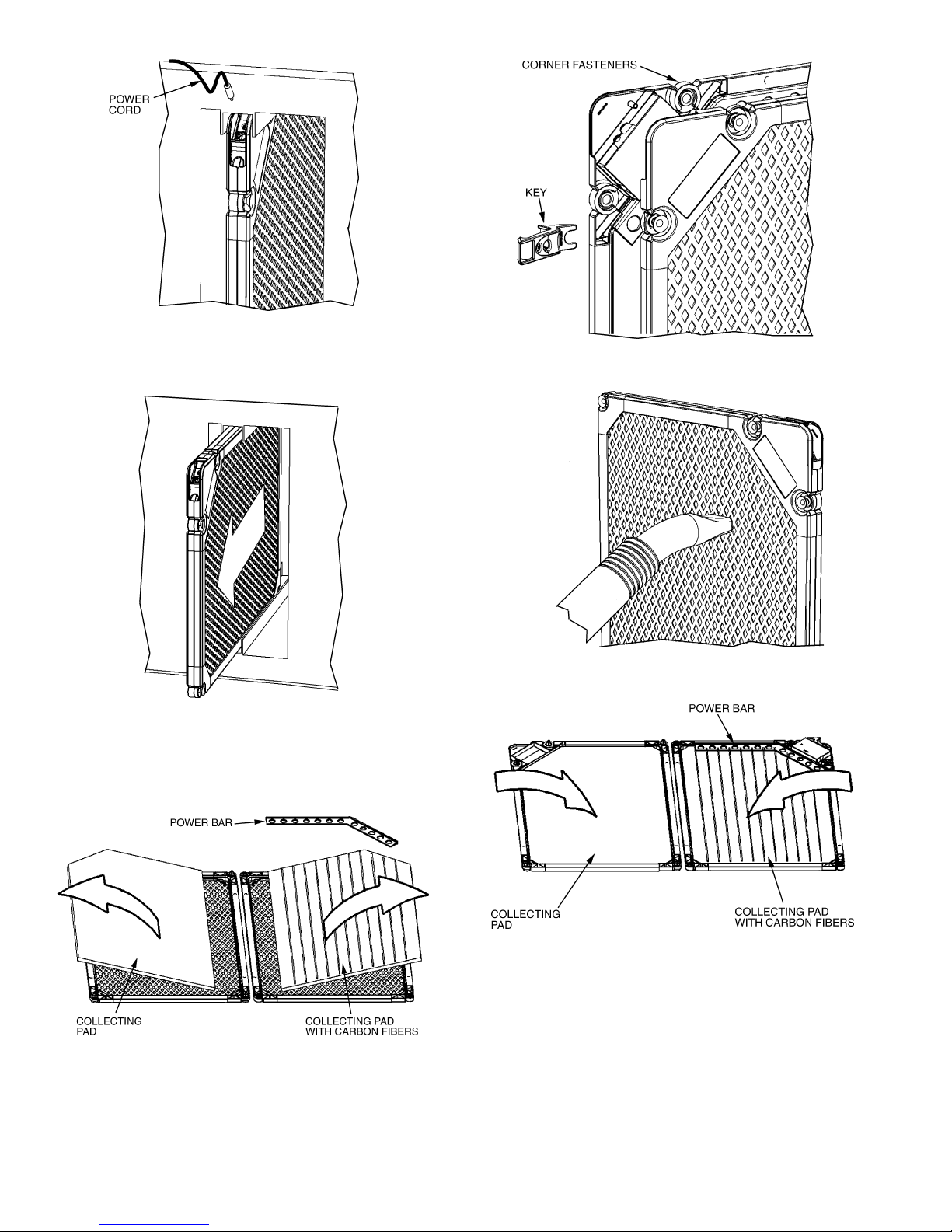
To replace the collecting pads:
1. Turn off furnace fan.
2. Disconnect power cord from the electronic air cleaner.
See Fig. 3.
3. Remove electronic air cleaner from filter rack. See
Fig. 4.
4. Lay the electronic air cleaner down. Open up the
frames so the collecting pads are exposed. See Fig. 5.
NOTE: If required, use the key to open the 5 corner
fasteners on the electronic air cleaner frames. See
Fig. 6.
5. Remove the power bar. Remove and discard both col-
lecting pads. See Fig. 5.
6. Vacuum the outside screens to remove all dust and res-
idue. See Fig. 7. The outside screens can be washed
with warm soapy water if needed. Be sure to dry
screens thoroughly before re-installing electronic air
collecting pads.
7. Install new collecting pads. Place power bar over col-
lecting pad with carbon fibers. The power bar must be
in contact with the carbon fiber collecting pad in order
for the electronic air cleaner to operate correctly. See
Fig. 8. Never wash the collecting pads.
8. Close the electronic air cleaner frames together and
lock all 5 corner fasteners (if required). Make sure all
the components are properly placed.
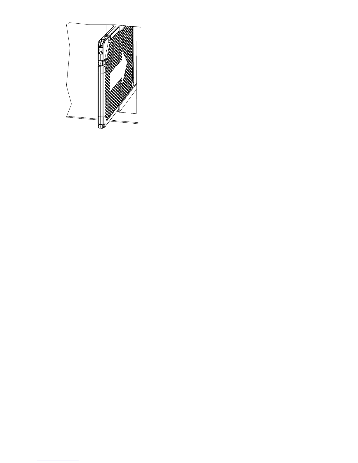
9. Place the electronic air cleaner back in the filter rack.
See Fig. 9.
10. Re-connect the power cord to the electronic air
cleaner. Check that green power supply LED is lit.
11. Turn on furnace fan.
Connecting the electronic air cleaner to a higher voltage
power supply will cause damage to the electrical compo-
nents of the electronic air cleaner. Do not connect to any
power source higher than 30-V.
Injury or electric shock could result. Make sure to turn fur-
nace off before performing any maintenance or removing
any components. Unplug power supply cord from elec-
tronic air cleaner before removing from filter rack.
Make sure electronic air cleaner is completely dry before
re-installing and turning on power. Damage to electronic
air cleaner could result.
Fig. 2 — Electronic Air Cleaner Wiring
NOTE: If one terminal of power source
is grounded, hook the white stripe wire
to this terminal
4
Fig. 3 — Power Cord Removal
Fig. 4 — Electronic Air Cleaner Removal
Fig. 5 — Collecting Pad Removal
Fig. 6 — Opening Corner Fasteners with Key
Fig. 7 — Vacuum Outer Screens
Fig. 8 — Install Replacement Collecting Pads
5
TROUBLESHOOTING
If the electronic air cleaner stops operating, verify that the
green high voltage power supply light is on. If the light is off,
check wiring and power supply. Make sure that the power cord
is plugged in and connected to the power supply.
If the orange LED light is on, perform the Collecting Pad
Replacement procedure in the section on page 3. Make sure
power bar is properly placed and is in contact with the carbon
fiber collecting pad.
Fig. 9 — Replacing Electronic Air Filter

6
ELECTRONIC AIR CLEANER
LIMITED TWO-YEAR WARRANTY
LIMITED TWO-YEAR WARRANTY — This CARRIER CORPORATION product is warranted to be free from
defects in material and workmanship under normal use and maintenance for two years. The warranty does not
apply to replacement of the disposable media collecting pads, which will need to be replaced three or four times
a year depending on usage. A new or remanufactured part to replace the defective part will be provided without
charge for the part itself, through a qualified servicing CARRIER CORPORATION dealer or service PROVIDED
the defective part is returned to our distributor.
THIS WARRANTY DOES NOT INCLUDE ANY ADDITIONAL LABOR ALLOWANCE, or other costs incurred
for diagnosis, repairing, removing, installing, shipping, servicing, or handling of either defective parts or replace-
ment parts. SUCH COSTS MAY BE COVERED BY a separate warranty provided by the installer.
LIMITATIONS OF WARRANTIES — ALL IMPLIED WARRANTIES (INCLUDING IMPLIED WARRANTIES OF
MERCHANTABILITY) ARE HEREBY LIMITED IN DURATION TO THE PERIOD FOR WHICH THE LIMITED
WARRANTY IS GIVEN. THE EXPRESSED WARRANTIES MADE IN THIS WARRANTY ARE EXCLUSIVE
AND MAY NOT BE ALTERED, ENLARGED, OR CHANGED BY ANY DISTRIBUTOR, DEALER, OR OTHER
PERSON WHATSOEVER.
ALL WORK UNDER THE TERMS OF THIS WARRANTY SHALL BE PERFORMED DURING NORMAL WORK-
ING HOURS. ALL REPLACEMENT PARTS, WHETHER NEW OR REMANUFACTURED, ASSUME AS THEIR
WARRANTY PERIOD ONLY THE REMAINING TIME PERIOD OF THIS WARRANTY.
CARRIER WILL NOT BE REPONSIBLE FOR:
1. Normal maintenance as outlined in the installation instructions including replacement of media collecting
pads.
2. Damage or repairs required as a consequence of faulty installation or application by others.
3. Damage or repair needed as a consequence of any misapplication, abuse, improper servicing, unauthorized
alteration or improper operations.
4. Damage as a result of floods, winds, fires, lightning, accidents, corrosive atmosphere, or other conditions
beyond the control of CARRIER CORPORATION.
5. Parts not supplied or designated by CARRIER CORPORATION.
6. CARRIER CORPORATION products installed outside the continental U.S.A., Alaska, Hawaii and Canada.
7. ANY SPECIAL INDIRECT OR CONSEQUENTIAL PROPERTY OR COMMERCIAL DAMAGE OF ANY
NATURE WHATSOEVER. Some states do not allow the exclusion of incidental or consequential damages, so
the above limitation may not apply to you.
Model No. ____________________________ Unit Serial No. _____________________________________
Date of Installation _____________________ Installed by _______________________________________
Name of Owner _______________________ Address of Installation _______________________________

7
Manufacturer reserves the right to
discontinue, or change at any time,
specifications or designs without notice
and without incurring obligations.
REPLACEMENT COMPONENTS DIVISION
© CARRIER CORPORATION 2001 12/01 LITERATURE NUMBER P103-4SI
PRINTED IN U.S.A. CATALOG NO. 570-470
Your Assurance of Quality
This Totaline® product is backed with a two-year
warranty by Carrier Corporation, the world’s largest
manufacturer of air conditioning, heating, and
refrigeration products.
This manual suits for next models
15
Table of contents
Other TOTALINE Air Cleaner manuals

TOTALINE
TOTALINE P102-BB14A Manual

TOTALINE
TOTALINE P103-R1700G User manual

TOTALINE
TOTALINE Star CG1000 Series User manual

TOTALINE
TOTALINE P103-RRUVL-012 User manual

TOTALINE
TOTALINE P102-400DM User manual

TOTALINE
TOTALINE P103-QUATTRO User manual

TOTALINE
TOTALINE Gold P102-350 User manual

TOTALINE
TOTALINE P102-12 Manual


