TouchNetix aXiom AX54A EVK User manual

aXiom AX54A EVK Quick Start Guide
1 Introduction
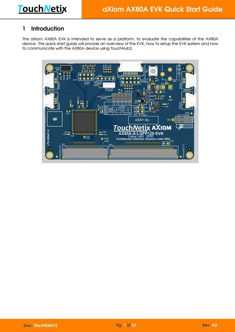
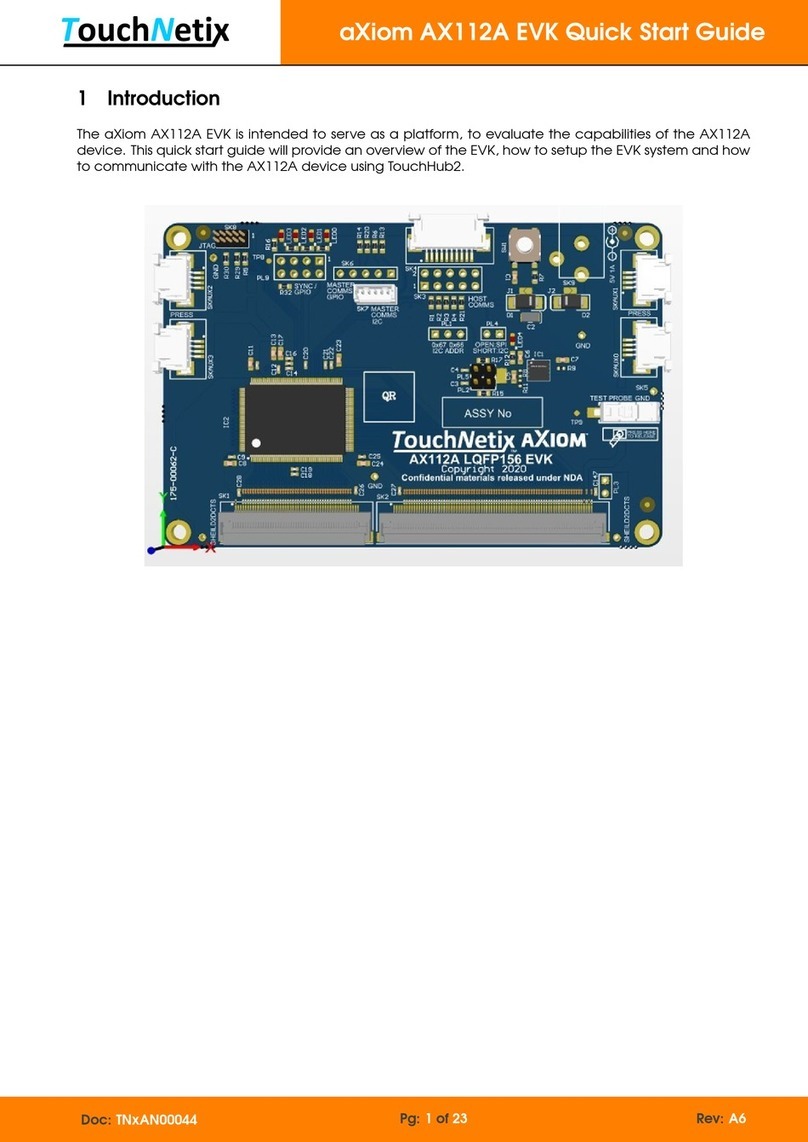
The aXiom AX54A EVK is intended to serve as a platform, to evaluate the capabilities of the AX54A
device. This quick start guide will provide an overview of the EVK, how to setup the EVK system and how
to communicate with the AX54A device using TouchHub2.
Doc: TNxAN00075 Pg: 1of 23 Rev: A2

aXiom AX54A EVK Quick Start Guide
Contents
1 Introduction 1
2 Terminology 3
3 Getting Started With The AX54A EVK 4
4 TouchHub2 Software 7
4.1Reports..................................................... 7
4.2TouchDrawing ................................................ 7
4.3 Loading and Saving AX54A Configurations . . . . . . . . . . . . . . . . . . . . . . . . . . . . . . . 8
4.4 Loading New AX54A Device Firmware . . . . . . . . . . . . . . . . . . . . . . . . . . . . . . . . . . 9
4.5ProtocolBridgeModes ........................................... 10
4.6 Updating the Protocol Bridge Firmware . . . . . . . . . . . . . . . . . . . . . . . . . . . . . . . . . 11
4.7LicenceKey(Optional)........................................... 12
5 AX54A EVK Overview 13
5.1EVKContents................................................. 13
5.2AX54AEVKHeaders............................................. 14
5.2.1HostCommsHeader-SK3 ..................................... 14
5.2.2HostCommsmode-PL6 ...................................... 15
5.2.3 Master Comms GPIO Header - SK6 . . . . . . . . . . . . . . . . . . . . . . . . . . . . . . . . 16
5.2.4 Master Comms I2CConnector-SK7 ............................... 16
5.2.5Sync/GPIOHeader-PL9 ..................................... 16
Appendix A References 17
Appendix B EVK Dimensions 18
Appendix C Bridge Board Dimensions 19
Appendix D EVK Schematic 20
Appendix E Legal Copyright and Disclaimer 22
Appendix F Document History 23
List of Figures
3-1AX54AEVKConnectionImage ...................................... 5
3-2 TouchHub2 Drawing Window, Target Information and Settings . . . . . . . . . . . . . . . . . . . 6
4.2-1EnableDrawing .............................................. 7
4.3-1 Loading a New Configuration File in TouchHub2 . . . . . . . . . . . . . . . . . . . . . . . . . . . 8
4.3-2 Saving a Configuration File in TouchHub2 . . . . . . . . . . . . . . . . . . . . . . . . . . . . . . . 8
4.4-1 Loading New aXiom Device Firmware in TouchHub2 . . . . . . . . . . . . . . . . . . . . . . . . 9
4.5-1BridgeModeSelect............................................ 10
4.6-1BridgeFirmwareUpdate ......................................... 11
4.6-2BridgeFirmwareVersion ......................................... 11
4.7-1TouchHub2LicenceEdit ......................................... 12
4.7-2LicencingWindow............................................. 12
5.2.2-1 EVK Communication Mode Select . . . . . . . . . . . . . . . . . . . . . . . . . . . . . . . . . . 15
5.2.2-2 Bridge Board Communication Mode Select . . . . . . . . . . . . . . . . . . . . . . . . . . . . 15
B-1EVKDimensions ............................................... 18
C-1BridgeBoardDimensions ......................................... 19
D-1EVKSchematic-Page1 .......................................... 20
D-2EVKSchematic-Page2 .......................................... 21
Doc: TNxAN00075 Pg: 2of 23 Rev: A2

aXiom AX54A EVK Quick Start Guide
2 Terminology
Term / Abbreviation Description
EVK aXiom AX54A Evaluation Kit.
FFC Flat Flex Cable.
FPC Flexible Printed Circuit.
GPIO General Purpose Input/Output.
I2C Inter-Integrated Circuit, synchronous two wire communication serial bus.
Bridge
The Protocol Bridge board is a module that communicates with the AX54A
device over I2C or SPI and presents a USB HID device to the host system. In
effect, it acts as a USB to I2C/SPI translator.
Report(s) Messages to the host from the AX54A device.
SPI Serial Peripheral Interface, synchronous four wire communication serial bus.
Target Either a proximity, hover or a touch detection.
TouchHub2 TouchNetix proprietary software; used to demo, tune and load
firmware/configuration files to the aXiom device via the Bridge.
Touch Screen This is an assembly comprising of a touch sensor and FPC bonded to a glass lens.
Table 2-1: Application Note Terminology and Abbreviations
Doc: TNxAN00075 Pg: 3of 23 Rev: A2

aXiom AX54A EVK Quick Start Guide
3 Getting Started With The AX54A EVK
To start using the AX54A EVK system you will need the following:
1. A PC running Windows 10 operating system (minimum requirement)
2. AX54A EVK board (supplied)
3. Bridge board (supplied)
4. USB A to mini USB B cable (supplied)
5. A TouchNetix touch screen (other compatible touch screens can be used)
6. FFC cable (supplied)
7. TouchHub2 software
The following steps explain how to set up the AX54A EVK system:
1. Connect the touch screen to the AX54A EVK board. (make a note of the number printed on the
underside of the touch screen starting ’840-’ as you will need this later)
(a) Lift the latches on connector SK1 on the EVK board.
(b) Align the FPC attached to the touch screen with SK1 on the EVK board ensuring that the gold
contacts are facing downwards into the connector. (This needs to be done at a slight angle
to allow the tabs on the edge of the FPC to engage in the connector).
(c) Ensure that the FPC is fully inserted into connector SK1 before fully closing the latches.
2. Connect the EVK board to the TNxAC-009 Bridge board.
(a) On both of the PCB’s, ensure that you have pulled the tabs on either side of the connectors
out, so that the cable can be slid in easily.
(b) Before inserting the FFC into the connectors, ensure that the silver contacts are facing upwards.
(c) Insert the FFC into each of the connectors until fully inserted and then press the tabs either side
back in, to lock the cable in place.
3. Connect the Bridge board to a Windows based host PC using the supplied or compatible USB
cable. (The host PC requires a USB2.0 or newer socket.)
(a) The Bridge board provides power to the EVK when connected to the host.
(b) When the Bridge board is powered, there are 2 LED’s that should be on.
i. LED1 and LED2, as labeled on the board.
(c) When the EVK is powered, there is 1 LED that should be on.
i. LED4 - Located near PL2.
4. Install and launch TouchHub2.
(a) TouchHub2 will automatically discover the first available Bridge once running.
(b) You should then see ’Connected’ in the bottom left hand corner of the window.
(c) Select ’Drawing’ from within the ’Main Menu’ at the top of the screen.
(d) TouchHub2 also has a ’Quick Start guide’ within the software which can be found in the ’Help’
menu.
Doc: TNxAN00075 Pg: 4of 23 Rev: A2

aXiom AX54A EVK Quick Start Guide
The EVK setup should look like the the following image.
Figure 3-1: AX54A EVK Connection Image
Key Component
1Touch Screen.
2aXiom AX54A EVK board.
3FFC between AX54A EVK board and the Bridge board.
4Bridge board (TNxAC-009).
5USB connection to the host.
Table 3-1: AX54A EVK Connections
Doc: TNxAN00075 Pg: 5of 23 Rev: A2

aXiom AX54A EVK Quick Start Guide
The different views seen here, can be selected by opening the ’Report Data Views’ menu. Views that
display real-time target data will reference u41 in the view title. The ’Drawing Settings’ in the ’Report
Data Views’ menu, will allow for different methods of visualizing the target data.
Figure 3-2: TouchHub2 Drawing Window, Target Information and Settings
Doc: TNxAN00075 Pg: 6of 23 Rev: A2

aXiom AX54A EVK Quick Start Guide
4 TouchHub2 Software
TouchHub2 is a proprietary TouchNetix application that has been designed to configure the aXiom
family of touch controllers. Without a licence key, TouchHub2 will run in a demo mode, which enables
the drawing interface and access to information regarding the reports that the aXiom device is generating.
With a licence key, different tuning and configuration options will be available, depending on the type
of licence you are issued with. TouchHub2 also enables configuration files to be loaded and/or saved,
as well as new firmware to be loaded to the device.
4.1 Reports
Reports are data messages that the aXiom device generates, to provide the host with real-time information.
There are two main reports that will be observed. (Other reports may be observed, and can be ignored
for the sake of this quick start guide.)
• u01 - System Report
–Heartbeat message from the firmware to notify the host that the aXiom device is functioning.
–A system report message is also sent at aXiom boot.
–A typical configuration will generate this heartbeat message once per second.
• u41 - Target Report
–This report includes all proximity, hover and touch targets and their detection states.
–All target statuses are reported in a single report.
–A typical configuration will generate a target report message after every touch panel measurement
frame.
4.2 Touch Drawing
The Drawing window in TouchHub2 is used to verify that touches, hover and proximity targets are correctly
reported by the aXiom device. Before the drawing mode can become active, it needs to be enabled
by moving the switch in the window from ’Off’ to ’On’. This will allow TouchHub2 to consume the u41
target reports from the aXiom device and draw the appropriate markers/lines.
Figure 4.2-1: Enable Drawing
For more help with TouchHub2 use the help guide referred to in the ’Quick Start guide’ within the
software which can be found in the ’Help’ menu.
Doc: TNxAN00075 Pg: 7of 23 Rev: A2

aXiom AX54A EVK Quick Start Guide
4.3 Loading and Saving AX54A Configurations
The configuration file, contains all the necessary register settings to tune the AX54A to the physical
characteristics of the sensor connected to it, configure measurement modes, process measurement
results and react to environmental effects such as noise and temperature changes. To load or save
configuration files, first open the ’Configuration’ view within the ’Device Views’ menu.
Figure 4.3-1: Loading a New Configuration File in TouchHub2
If loading a new configuration file received from TouchNetix, select ’Load Configuration’ and then
browse for the file in the pop-up window that appears, and click ’open’. On the window that remains
open, do not change any of the tick boxes unless instructed to do so by TouchNetix, and click ’Load’
to load the file. Once the new configuration file has been loaded, the EVK board will reset
automatically and TouchHub2 will reconnect.
Figure 4.3-2: Saving a Configuration File in TouchHub2
To save a configuration file, select ’Save Configuration’, enter the name and location then click ’Save’.
Doc: TNxAN00075 Pg: 8of 23 Rev: A2

aXiom AX54A EVK Quick Start Guide
4.4 Loading New AX54A Device Firmware
TouchHub2 can be used to update the aXiom firmware. It will handle the update process and automatically
reset the device once the download is complete. Depending on the changes in the firmware, the
configuration file may need to be reloaded after downloading new firmware. See section Loading and
Saving AX54A Configurations for how to load configuration files. The firmware is contained within an .alc
file.
Figure 4.4-1: Loading New aXiom Device Firmware in TouchHub2
Doc: TNxAN00075 Pg: 9of 23 Rev: A2

aXiom AX54A EVK Quick Start Guide
4.5 Protocol Bridge Modes
The Bridge can be configured to enumerate as a USB touch digitizer device, whereby touch inputs will
generate appropriate HID reports for the host operating system to respond to. To change the Bridge
mode, navigate to the ’Connection’ menu and select the ’System Maintenance’ option from the drop
down menu. Click the ’OK ’ button in the warning pop-up window and then, on the next window, ensure
that the Bridge tab is selected. The Bridge supports three modes and can be selected as per Figure 4.5-1
Bridge Mode Select:
1. TBP Basic Mode - Allows TouchHub2 to communicate with the aXiom device being configured and
tested.
2. TBP Digitizer Mode - The Bridge will enumerate as multi-touch digitizer and allow the first 5 targets to
be sent to Windows to process.
3. TBP Absolute Mouse Mode - The Bridge will control the mouse based on the state of the targets.
Note: In Digitizer and Absolute Mouse Modes windows will respond to messages sent by the Bridge
and treat it as an input device. Therefore, if the aXiom device is not configured correctly you may get
unwanted input to the OS. To avoid this, keep the Bridge in Basic mode until a valid configuration has
been loaded into the aXiom device.
Once the desired mode has been selected, click the ’Apply’ button. The Bridge will reset and
re-enumerate with Windows.
Figure 4.5-1: Bridge Mode Select
Doc: TNxAN00075 Pg: 10 of 23 Rev: A2

aXiom AX54A EVK Quick Start Guide
4.6 Updating the Protocol Bridge Firmware
It may be necessary to update the Bridge firmware from time to time and this can be done using the
TouchHub2 application. To access this option, select the ’Connection’ menu and then the ’System
Maintenance’ option from the drop down menu. This will open the System Maintenance window and
you should then select the ’Bridge’ tab. Click ’Bridge Reflash’ and a file selector window will open,
select from either a *.th2bridgefw, *.elf or *.dfw file which contains the new Bridge firmware.
Figure 4.6-1: Bridge Firmware Update
Once the firmware update is complete, the Bridge will reset and TouchHub2 will automatically
reconnect to the Bridge. The Bridge firmware version can be verified in the status bar of TouchHub2.
Figure 4.6-2: Bridge Firmware Version
Doc: TNxAN00075 Pg: 11 of 23 Rev: A2

aXiom AX54A EVK Quick Start Guide
4.7 Licence Key (Optional)
TouchHub2 requires a licence key to access and tune aXiom devices. Without a licence key,
TouchHub2 operates in Demo mode. To request a new licence or an extension to an existing licence,
please contact TouchNetix. Enter the licence key by selecting the ’Help’ menu and selecting ’Licence’
from the drop down menu.
Figure 4.7-1: TouchHub2 Licence Edit
Click on the ’Test’ button to ensure the key is valid and has been inputted correctly. Once the key is
verified, click ’Save’. The licence expiry date is shown in the pop-up.
Figure 4.7-2: Licencing Window
Doc: TNxAN00075 Pg: 12 of 23 Rev: A2

aXiom AX54A EVK Quick Start Guide
5 AX54A EVK Overview
5.1 EVK Contents
The EVK contains a complete system to get up and running with the aXiom AX54A device. The EVK is
comprised of:
1. AX54A EVK board featuring the AX54A device.
2. TouchNetix Touch Screen.
3. TNxAC-009 Bridge board with USB cable and a FFC to connect to the EVK board.
Key Silkscreen Identifier Name
1IC3 AX54A Device.
2SK1 Touch Screen FPC Connector.
3SKAUX0, SKAUX1,
SKAUX2, SKAUX3 Press Sense FPC Connectors.
4SW1 AX54A Reset Button.
5SK4 Bridge Board Connector.
6SK2 Host Comms Header.
7PL4 Host Comms Mode Select; SPI or I2C.
8SK6 Master Comms GPIO Header.
9SK7 Master Comms I2C Connector.
10 PL9 Sync / GPIO Header.
11 LED1, LED2, LED3 GPIO LEDs.
12 SK9 Power Barrel Jack, 5V 1A.
13 SK7 Metal touch Ground Wire Connector.
Table 5.1-1: AX54A EVK Overview
Doc: TNxAN00075 Pg: 13 of 23 Rev: A2

aXiom AX54A EVK Quick Start Guide
5.2 AX54A EVK Headers
5.2.1 Host Comms Header - SK3
Pin Name Description
1VDDIN 5V Power
2SLVSDA/SCK SPI: SCK
I2C: SDA
3SLCSCL/nSS SPI: Slave Select
I2C: SCL
4nReset Reset AX54A Device
5SLVnIRQ Active Low IRQ signal from
AX54A Device to Host
6GND Ground
7SLVI2CADDRSEL/MOSI SPI: MOSI
I2C: Address select
8nSLVI2C/MISO SPI: MISO
I2C: I2C Comms Select
9SLVSDA/SCK SPI: SCK
I2C: SDA
10 SLVSCL/nSS SPI: Slave Select
I2C: SCL
Table 5.2.1-1: Host Comms
This host comms header is an exact pin-out of SK4, the FFC connector to the Bridge board. This connector
is useful to provide a direct connection to the aXiom AX54A’s SPI and I2C interfaces. Some of the pins
have multiple functions which are dependent on the Host Comms mode - PL6, these are identified in
the pin-out table as SPI and I2C.
Doc: TNxAN00075 Pg: 14 of 23 Rev: A2

aXiom AX54A EVK Quick Start Guide
5.2.2 Host Comms mode - PL6
Pin Name Description
1SLVI2CADDRSEL/MOSI SPI: MOSI
I2C: Address select
2VDDI VDDI
3SLVI2CADDRSEL/MOSI SPI: MOSI
I2C: Address select
4GND Ground
5nSLVI2C SPI: MOSI
I2C: I2C Comms select
6GND Ground
7nSLVI2C SPI: MOSI
I2C: I2C Comms select
8SLVI2CADDRSEL/MOSI SPI: MOSI
I2C: Address select
9LIN EN LIN EN
10 SLVnIRQ Active Low IRQ signal from AX54A Device to
Host
Table 5.2.2-1: Host Comms Mode Select Header
The AX54A EVK board will use the SPI communication interface to the host by default, with nothing set
on the header. By fitting jumpers in accordance with the silkscreen diagram in Figure 5.2.2-1, you can
change the communication mode accordingly.
I2C 0x66 address is selected in the middle image, I2C 0x67 address is selected in the right image.
Figure 5.2.2-1: EVK Communication Mode Select
The Bridge always needs to be set to be the same communication protocol as the AX54A EVK. The
board comes with no link fitted on the PL3 ’COMM SEL’ header which is correct for SPI, should you want
I2C then you would need to fit a 2 pin header and jumper.
Figure 5.2.2-2: Bridge Board Communication Mode Select
Doc: TNxAN00075 Pg: 15 of 23 Rev: A2

aXiom AX54A EVK Quick Start Guide
5.2.3 Master Comms GPIO Header - SK6
Pin Name Description
1MSTCOMMS0 GPIO
2MSTCOMMS1 GPIO
3MSTCOMMS2 GPIO
4MSTCOMMS3 GPIO
5GND Ground
Table 5.2.3-1: Master Comms GPIO Header
All MSTCOMMS pins have 3K3 ohm pull-up resistors to 3V3. The master comms interface is intended to
be connected to a device, that will trigger/control any haptic actuators based, on the haptic hotspots
that are defined within the AX54A device configuration file. Refer to TNxAN00036 aXiom Touch Controller
Haptics Drive for more information.
5.2.4 Master Comms I2C Connector - SK7
Pin Name Description
1VDD 5V power
2MSTCOMMS0 Master I2C SDA
3MSTCOMMS1 Master I2C SCL
4MSTCOMMS2 IRQ
5GND Ground
Table 5.2.4-1: Master Comms I2C Connector
This I2C bus is independent from the host comms I2C bus. All MSTCOMMS pins have 3K3 ohm pull-up
resistors to 3V3. The master comms interface is intended to be connected to a device, that will trigger/control
any haptic actuators based, on the haptic hotspots that are defined within the AX54A device configuration
file. Refer to TNxAN00036 aXiom Touch Controller Haptics Drive for more information.
5.2.5 Sync / GPIO Header - PL9
Pin Name Description
1VDD 5V Power
2GPIO0 GPIO
3GND Ground
4GPIO1 GPIO
53V3 3.3V Power
6GPIO2 GPIO
7GPIO2 GPIO
8Not Connected Not Connected
Table 5.2.5-1: Sync / GPIO Header
Doc: TNxAN00075 Pg: 16 of 23 Rev: A2
Table of contents
Other TouchNetix Computer Hardware manuals
Popular Computer Hardware manuals by other brands

Sun Microsystems
Sun Microsystems Netra ft 1800 Hardware reference manual
Emprex
Emprex COL-3101 installation guide
QNAP
QNAP QuTS hero Turbo Station TS-1655-8G Quick installation guide
Cypress Semiconductor
Cypress Semiconductor MoBL CY62146ESL Specification sheet

Sierra Wireless
Sierra Wireless Sierra Wireless AirCard 890 quick start guide

Meinberg
Meinberg TCR510PCI operating instructions


