TouchStar EMH500 Series User manual
TouchStar Americas, Inc. Page 1 of 25
T:\HARDWARE & SUPPORT\TSP Products\EMH Manuals\EMH500 Series Installation Manual 2.1a.doc
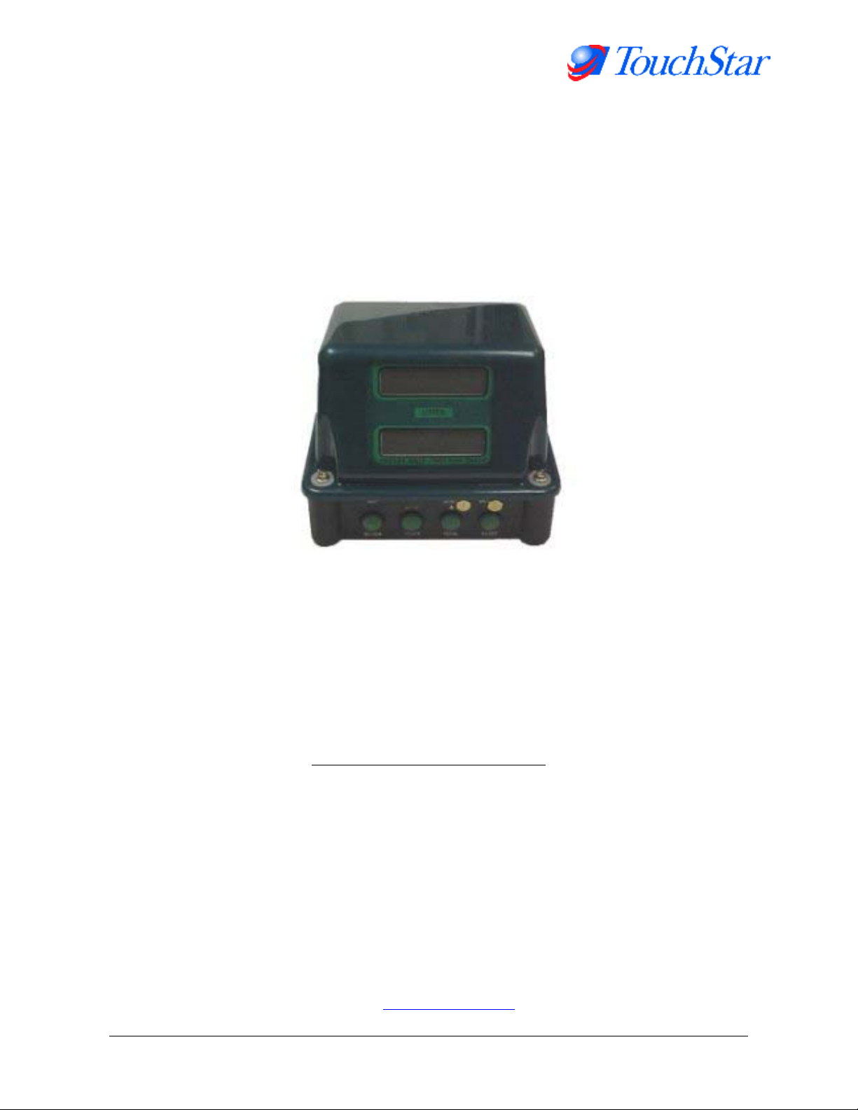
EMH500 Series
Electronic Register
Installation Manual
Version 2.1a
05 November 2001
Other Manuals in the Series:
Hardware Reference Manual
Software Settings Reference Manual
Developer Interface Manual
General User Guide
Revision History (Internal Use Only)
TouchStar Americas, Inc.
5147 South Garnett Road, Suite D
Tulsa, OK, 74146
USA
Tel: +1(918)307-7100
Fax: +1(918)307-7190
Email: [email protected]

TouchStar Americas, Inc. Page 2 of 25
T:\HARDWARE & SUPPORT\TSP Products\EMH Manuals\EMH500 Series Installation Manual 2.1a.doc
Table of Contents
1. Introduction ............................................................................................................................................ 3
1.1 Use of this Manual ............................................................................................................................. 3
1.2 Document Revision History................................................................................................................ 3
2. Parts Supplied........................................................................................................................................ 3
3. Installation – Mounting ........................................................................................................................... 4
3.1 EMH500 Register............................................................................................................................... 4
3.1.1 Label Diagram ............................................................................................................................ 4
3.1.2 Mounting on an LC Meter ........................................................................................................... 5
3.1.3 Mounting on a Neptune Meter .................................................................................................... 5
3.2 Mounting With ERP100 Remote Pulser ............................................................................................. 5
3.2.1 Remote Pulser - LC Meter .......................................................................................................... 5
3.2.2 Remote Pulser - Neptune Meter ................................................................................................. 6
3.3 Power Junction Box (EJB101)............................................................................................................ 6
3.4 Remote Display.................................................................................................................................. 6
3.5 Temperature Probe............................................................................................................................ 6
4. Installation – Wiring ................................................................................................................................ 7
4.0.1. Recommended Cable Types For System Wiring ........................................................................ 8
4.1.2 Shielding & Earth Resistance ..................................................................................................... 8
Positive Power Connections................................................................................................................... 9
Shielding ................................................................................................................................................ 9
4.1 EMH500 Register............................................................................................................................. 11
4.2 Remote Pulser ................................................................................................................................. 11
4.2.1 ERP100 Remote Pulser............................................................................................................11
4.2.2 Single Pulse Input..................................................................................................................... 11
4.3 EJB101 Power Junction Box............................................................................................................ 11
Connections ......................................................................................................................................... 11
4.3.1 EJB101 Wiring Diagram-For power and signal only. See previous wiring diagram for shielding12
4.4 Remote Display................................................................................................................................ 13
4.5 Temperature Probe.......................................................................................................................... 13
4.6 TouchStar Blaster Printer................................................................................................................. 13
4.7 Slip Printer ....................................................................................................................................... 13
4.8 Connecting Multiple EMH500 registers ............................................................................................14
5. Calibration Set-up................................................................................................................................. 14
5.1 Typical Printout ................................................................................................................................ 14
5.2 Setting the Average K-factor (KO CAL)............................................................................................ 14
6. Connecting a Ticket Printer .................................................................................................................. 14
6.1 Ticket Printer DIP Switch Settings.................................................................................................... 14
6.2 Installing the TouchStar Blaster Printer............................................................................................ 14
6.3 Checking the Operation of the Ticket Printer....................................................................................14
6.4 Connecting multiple registers to one printer. .................................................................................... 14
7. Various DIP Switch Settings................................................................................................................. 14
7.1 EMH500 Mainboard DIP switch specifications. ................................................................................ 14
8. Displayed Messages ............................................................................................................................ 14
9. Changing the EPROM.......................................................................................................................... 14
10. General Troubleshooting...................................................................................................................... 14
10.1 Temperature Probe.......................................................................................................................... 14
Appendix....................................................................................................................................................... 14
1EMH500 Calibration Certificate........................................................................................................ 14
EMH500 Calibration Certificate ............................................................................................................ 14

TouchStar Americas, Inc. Page 3 of 25
T:\HARDWARE & SUPPORT\TSP Products\EMH Manuals\EMH500 Series Installation Manual 2.1a.doc
1. Introduction
Thank you for supporting this product and taking the time to read this installation manual.
The Liquip Group has been manufacturing Electronic Meter Heads (Electronic Registers) for over 15 years.
The EMH500 being the 5th and latest series has undergone a complete transformation with many new
technologies being employed to greatly enhance overall functionality.
The EMH500 has been specifically designed to meet the many different Weights & Measures standards for
metered delivery systems found around the world. Especially, where the use of mobile computing, point of
sale invoicing and other electronic administration automation is being considered.
The EMH500 is a significant departure from traditional Electronic Meter Heads. While the device remains
fairly self-contained and easy to install, the large number of set-up parameters and functional options
suggests a good understanding of this manual will greatly reduce potential configuration errors.
1.1 Use of this Manual
This manual is designed as a guide for experienced installation technicians familiar with all local codes and
standards associated with this type of work. It is supplied with the intent of providing a broad view on
installing and configuring the EMH500 only.
It should be used as a reference for both basic (Stand-alone) and more complicated (Interfaced with
Computer) installations. However, separate manuals provide the necessary details for associated equipment.
We recommend you become familiar with the contents of this manual before attempting to install the product.
We also assume you have detailed local knowledge on and certified where required in,
•Electrical Safety Standards.
•Weights & Measures certification and verification.
•Electronic systems installation.
•Hazardous Environment Installation (where applicable)
Ensuring compliance with the highest safety and regulatory standards is of critical importance.
1.2 Document Revision History
Version 1.0 – Original Document (combined manual)
Version 2.0 – Split into component documents 08/07/99
Version 2.1a – Revise power wiring and add shielding wiring diagrams 05/11/01
2. Parts Supplied
EMH500 Complete – P/NO: 699750
Comprising:
EMH500 Register Head
EJB101 Power / Junction Box
Aluminium Shaft Adaptor
Roll pin 1.5 x 10mm
Split pin 1.5 x 20mm stainless steel
4 off ¼” x ¾” UNF Mounting Bolts
The following parts are not supplied but are available from your local solution centre
¾” NPT Plug (for sealing unused conduit entry points)
¾” NPT to 20mm Reducing Bush (for adapting to metric conduit)
M8 x 30mm Bolts, Nuts and Washers (for mounting junction box)
Conduit Fittings
Conduit & Cable
Drive adaptors for various meters

TouchStar Americas, Inc. Page 4 of 25
T:\HARDWARE & SUPPORT\TSP Products\EMH Manuals\EMH500 Series Installation Manual 2.1a.doc
3. Installation – Mounting
3.1 EMH500 Register
3.1.1 Label Diagram
Ensure either the metric or imperial display labels are showing
Sticker that can be removed to show text underneath
Volume Corrected to 15 C
Volume Corrected to 60 F
LITRES
GALLONS

TouchStar Americas, Inc. Page 5 of 25
T:\HARDWARE & SUPPORT\TSP Products\EMH Manuals\EMH500 Series Installation Manual 2.1a.doc
3.1.2 Mounting on an LC Meter
Mounting bolts: 4 off ¼” x ¾” UNF with flat and spring washers. The 4 hole bolt pattern matches the standard
4 hole pattern of the LC Meter; a cover plate is used to enclosed the remaining parts of the LC meter head
mounting.
Without the LC Calibrator
•The LC Calibrator is not required for either setting the K-factor (done within the EMH500), or for shaft
speed reduction. The LC extension shaft kit (EMH500-21) replaces the calibrator. The kit includes
1. The extension shaft
2. The shaft support bush plate
3. Aluminium shaft adaptor
4. Roll pin 1.5 x 10mm
5. Split pin 1.5 x 20mm stainless steel
•The shaft support bush plate is mounted in place of the calibrator.
•The extension shaft attaches to the register with the aluminium shaft adaptor and fits down through the
bush and over the crown wheel shaft as the register is fitted.
•Screw in the 4 mounting bolts.
With the LC Calibrator
•The LC Drive Dog is attached to the aluminium shaft adaptor
•Using a 1/16” x 3/8” roll pin.
•The shaft adaptor is attached to the Register using a 1.5 x 20mm stainless steel split pin.
•The drive dog fits into the top of the calibrator as the register is placed onto the meter and the mounting
bolts done up.
3.1.3 Mounting on a Neptune Meter
Mounting bolts: 4 off ¼” x ¾” UNF with flat and spring washers.
•Mount the EMH-5 casting adaptor to the Neptune Meter using 2 off 3/8” x 1 ¼” UNC bolts with flat &
spring washers
•Attach the Neptune Drive fork to the aluminium shaft adaptor using a 1/16” roll pin.
•Attach the shaft adaptor to Register using a 1.5 x 20mm s/s Split pin.
•The Drive fork fits into the Star Drive as the register is placed onto the Casting Adaptor.
•Screw in the 4 mounting bolts.
3.2 Mounting With ERP100 Remote Pulser
Refer to Hardware Reference manual for diagrams.
3.2.1 Remote Pulser - LC Meter
Additional Parts required
Side Mount - 697732/001 - Mount Kit ERP100/LC Meter Direct
Top Mount - 697731/001 – Mount Kit ERP100/LC Meter Top
Installation
•Attach Drive dog
•Attach ERP100 to cast adaptor using screws supplied (3/8” UNC)
•Fit adaptor and ERP100 to meter

TouchStar Americas, Inc. Page 6 of 25
T:\HARDWARE & SUPPORT\TSP Products\EMH Manuals\EMH500 Series Installation Manual 2.1a.doc
3.2.2 Remote Pulser - Neptune Meter
Additional parts required
697734/001 - Mount Kit EPR100
•Attach 200-1 to 200-5 Casting
•Follow remote pulser instructions
3.3 Power Junction Box (EJB101)
•The location of the Junction Box is dependent on the length of cable to the Register and the length of
cable of the Temperature Probe.
•The standard length of cable to the Register is 1 metre. Optional lengths are 2, 3 and 4 metre.
•The EMH500 automatically calibrates for a change in the Temperature Probe cable length, whether it is
lengthened or shortened.
•The location should also allow for the easy removal of the lid and access for wiring
•The box is mounted to the chassis using 4 off 8mm bolts.
•Conduit threads in Ex e junction box are ¾” NPT. Adaptors can be used to change to 20mm.
3.4 Remote Display
•Ensure mounting of the Display is in plain view.
•The remote display should be securely mounted.
•Ensure vibration effects to the Display are minimal.
3.5 Temperature Probe
•The Temperature Probe can be mounted directly in product, or preferably, in a thermowell.
•Care needs to be taken for the location of the probe so that the wiring will be protected.
•The probe has a ¼” NPT thread.
•If the probe is mounted in a thermowell a conductive substance has to be used.
TouchStar Americas, Inc. Page 7 of 25
T:\HARDWARE & SUPPORT\TSP Products\EMH Manuals\EMH500 Series Installation Manual 2.1a.doc
4. Installation – Wiring
•The wiring and conduit must be done in conjunction with standards and rules of the local authorities.
•The Register and the cable to Junction box are intrinsically safe.
•Data and Power cable should be shielded.
•Input power is auto sensing between 11 – 30 V DC
•Input Power should be connected either to the main supply in the cabin of the vehicle or the Isolation
Switch.
•The power box is internally fused by 3 anti-surge fuses.
800mA glass 20x5mm
2 x 2Amp glass 20x5mm Relay outputs
•Typically the serial comm port 1 (Com 1) is connected to an invoicing system such as the TouchPC.
•A serial printer eg TouchStar Blaster Printer with a 9 pin D connector or an Epson Slip printer with a 25
pin D connector is typically connected to the serial comm port 2 (Com 2)
•All wiring should be run in conduit and all wires and conduit should be securely held with cable ties.
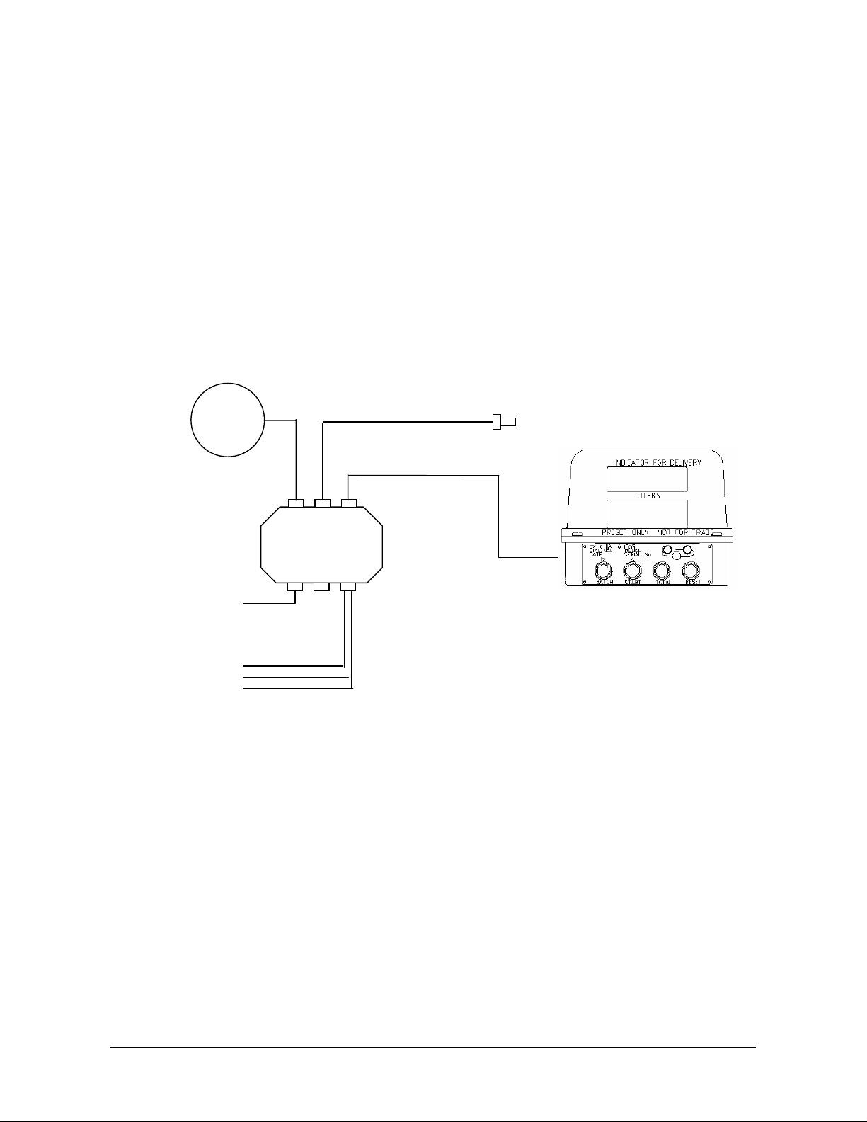
Typical Installation
Power Input
Com 1
Com 2
Temp Probe
EMH500 Register
Power Box
EJB 101
Solenoid
Relays
HI/LO Flow
Remote
Pulsar
ERP100
Optional

TouchStar Americas, Inc. Page 8 of 25
T:\HARDWARE & SUPPORT\TSP Products\EMH Manuals\EMH500 Series Installation Manual 2.1a.doc
4.0.1. Recommended Cable Types For System Wiring
Item Usage Cable type Comments
1. EMH500 to EJB 25 Core, 25 x 7/0 Foil shielded with drain
wire RS232 cable, 10.7mm N.O.D.
Polyurethane sheath
Supplied
2. Power Supply 2 Core Shielded (16 x 0.2) Foil shielded with
drain wire. (Red/Black)
Rated @ 24Vdc5A or 12Vdc
5A
3. RS232 Port 1 or 2 4 core 24AWG 7 x 0.2 Foil shielded with
drain wire
COMM 1 : Sheath Black
COMM 2 : Sheath BLUE
Wire colours inside are blue,
white, red and black
4. Temperature Probe N/A
5. HI-Speed Pulser 5 core 24 AWG (7 x 0.2) foil shielded cable
with drain wire
6. Remote reset Single core cable (7 x 0.2) Standard cable
7. Pulse Output 4 core 24AWG (7 x 0.2 ) Standard cable
8. Solenoid (each) 2 Core Shielded (16 x 0.2) Foil shielded with
drain wire. (Red/Black)
4.1.2 Shielding & Earth Resistance
Never rely on using the vehicle chassis as an electrically continuous common ground without first
measuring the resistance between the chosen earth point and the negative battery terminal. The
cabin earth point or the battery terminal.
Not checking the earth resistance could be the cause of intermittent equipment malfunctions with
operational reliability being sacrificed.
The measurement must be taken in the following manner:
•Extend the multimeter lead with a low resistance cable long enough to reach from the battery to
the chosen earth point. The resistance of this cable should be measured and taken into
account when calculating the final resistance.
•Disconnect the negative terminal from the battery and measure from the negative lead to the
point you intend to use as the central vehicle earth point. (The central vehicle earth point is the
point that all TouchStar equipment earth connections are connected to)
•The earth resistance should be measured for each vehicle and must be less than 1 ohm. (i.e.
the earth point resistance less the test lead resistance).
In the event that a resistance measurement of less than 1 ohm cannot be achieved it is necessary
to run a cable from the isolation switch or negative terminal of the battery into the cab for the
vehicle earth. The size of this cable should be equivalent to 65 x 0.3mm, 6mm Auto cable.

TouchStar Americas, Inc. Page 9 of 25
T:\HARDWARE & SUPPORT\TSP Products\EMH Manuals\EMH500 Series Installation Manual 2.1a.doc
Earth Resistance Measurement Diagram
Positive Power Connections
The connection to the positive terminal must be treated in the same way. There must be less than
1 ohm resistance between the Positive battery terminal and the positive connection point in the
EJB101. This includes wiring through fuse panels, ignition switches, relays.
Shielding
All shielded cables must be grounded at one end only at the central earth point.
Below 30 meters, one overall shield in multi-core cable is sufficient but above this distance every
cable should be individually screened.
Small millivolt signals should be transmitted by shielded twisted pair wire.
In this case all the register power and data cables must be shielded, and have their shields earthed
in the EJB101.
The shield on the Register cable from the cradle is connected to the shield on the cable from the
EJB 101 junction box. Where this cable connects to the EJB101 junction box the shield is
connected to the ground connection (as is the blue core wire, which is the signal ground
connection, and the red core wire, which is a spare). This is Register Com 1 in the attached
drawing.
The same is true for the shield on the printer comms cable. This is Register Com 2 in the attached
drawing.
The Power cable and the Temperature probe cables are grounded in the same way.
The 1-ohm reading between the EJB101 and the negative battery terminal applies as it does for
the cabin central earth point.
The 1-ohm reading between the EJB101 and the positive battery terminal also applies, as it does
for the cabin mounted equipment
Positive lead
_
+
Chassis
connection point
Disconnect
Earth terminal
Chassi Multi-
meter
Extended negative lead
(note resistance of lead
and subtract from total

TouchStar Americas, Inc. Page 10 of 25
T:\HARDWARE & SUPPORT\TSP Products\EMH Manuals\EMH500 Series Installation Manual 2.1a.doc
EJB101 Power Junction Box
PWR +
GND -
GND -
Temperature
probe
TX 1
Comm 1
RX 1
GND
TX 2
Comm 2
RX 2
GND -
DB 25
Connector
TouchStar Wiring Diagram - EMH500 Register
Gnd. Black
Pos.
3A
Red
Fuse Panel Area
in Cabin
White
Red
Black
Blue
Red
Black
Blue
White
Black
Blue
White
2
3
5
Crimps
White
Red
Black
Blue
Red
Black
Blue
White
Black
Blue
White
2
3
5
To
TouchPC
Link between pins 7 & 8
used for Blaster printer
onl
y
.
EMH-500
Register
Temperature
Probe
GND
-
B
B
A
White/Red
White/Blue
White
P/N 1052703. 2x24/0.2 Screened, Black sheath
P/N 1052700 4x7/0.2 Screened, Black
P/N 1052701 4x7/0.2 Screened, Blue
sheath
P/N 692710/001
P/N 692705/001
8
7
Shields are NOT
connected to D
connectors Note: Signal ground, red wire and
shield are connected together at
GND - terminal
Note: Signal ground, red
wire and shield are
connected together at GND
- terminal
To Printer
1x195/0.25, Black
sheath earth strap to
rear central earth.

TouchStar Americas, Inc. Page 11 of 25
T:\HARDWARE & SUPPORT\TSP Products\EMH Manuals\EMH500 Series Installation Manual 2.1a.doc
4.1 EMH500 Register
The EMH500 Register has a single cable connection from the junction box to the rear of the EMH500
Register. It is a bayonet style connector and is keyed for alignment.
4.2 Remote Pulser
4.2.1 ERP100 Remote Pulser
The Remote Pulser (ERP100) requires a 6 wire shielded cable connected to CON.104 in the EJB101 and
should be contained within a suitable conduit that satisfies local regulations.
The white plug inside the EMH500 that connects the internal pulser must be disconnected and secured to
the support bracket with a cable tie. Connecting both the internal and remote pulser will cause OPTO errors.
The shield is to be grounded at the EJB and care should be taken within the pulser so as not to interfere with
the rotational operation of the pulser.
The conduit entry is a ½” NPT thread and ½” NPT to 16mm adaptors are available.
4.2.2 Single Pulse Input
If a single pulse is used, connections inside the EJB101 are to P1 and GND with 0.4V and 1.5V thresholds
and single pulse input must be selected in the calibration settings of the EMH500. The internal pulser
connector located on the main board of the EMH500 must be disconnected as above.
4.3 EJB101 Power Junction Box
See attached wiring diagram.
Connections
Relay Connection (To Solenoids)
Rel1, Rel2 - The connection directly leading to the input of the solenoids
GND - Ground connection
Communication Port
TX1, TX2 - Data lines for sending data (transmit) from the EMH500 to the printer/Touch PC. This is
typically connected to the RX lines of the printer/Touch PC.
RX1, RX2 - The direct opposite of the TX lines. Used for receiving data from the printer/Touch PC
GND - Ground.
Remote Pulser Connection
V+ - Power for the remote pulser
Px - P1, P2, P3 lines are the three channels (pulse lines) used for calculating volume.
GND - Ground.
Temperature Probe Connection.
A - Connection for the white wire of the probe
B1, B2 - Two connections to the white/red and white/blue wires of the probe. A second wire is
required for compensating wire resistance.
GND - Ground (optional)
TouchStar Americas, Inc. Page 12 of 25
T:\HARDWARE & SUPPORT\TSP Products\EMH Manuals\EMH500 Series Installation Manual 2.1a.doc
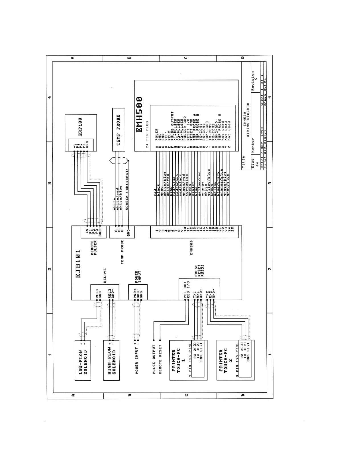
4.3.1 EJB101 Wiring Diagram-For power and signal only. See previous wiring
diagram for shielding

TouchStar Americas, Inc. Page 13 of 25
T:\HARDWARE & SUPPORT\TSP Products\EMH Manuals\EMH500 Series Installation Manual 2.1a.doc
4.4 Remote Display
Additional Parts required
4 Wire Data
2 Wire Power
10k Pull up Resistor (Reset)
¾” NPT - 20mm Adaptor (Brass)
20mm – 16mm Brass Adaptor
1070703 – 16mm Adaptors
Conduit
•Wire the Remote Display to the Power Junction Box at CON103 using shielded 2 Pair cable ensuring
shield is grounded at both ends.
•Refer to the Remote Display manual for input voltage and as to whether a pull up resistor is required on
the pulse input.
•Depending on whether the Remote Display is 24V or 12V will determine what voltage is supplied to the
Power Junction box as the input power is paralleled from the power box supply using 2 wire shielded
cable
4.5 Temperature Probe
1070703 16mm Adaptor and Seal Cap
¾” NPT/20mm (Brass)
20mm – 16mm Reducer (Brass)
1070701 - Conduit
697701/001 – Temperature Probe
The Temperature Probe should be wired to CON.105 of the Power Junction Box with the resistive path
between terminals 'A' & 'B'
The shield should be connected to the Ground terminal in the Power Junction Box
4.6 TouchStar Blaster Printer
The printer requires a 24V power supply. If the vehicle is 12V a power inverter must be connected.
The power is wired through a noise suppressor to the 2.1mm DC plug. The centre pin is positive.
The data connection is made to the 9 pin serial connector on the back of the printer.
Detailed connections to the TouchPC can be found in the appropriate TouchPC manual.
4.7 Slip Printer
The printer requires a 24V power supply. If the vehicle is 12V a power inverter must be connected.
The power is wired through a noise suppressor to the 3 pin connecter.
The data connection is made to the 25 pin serial connector on the back of the printer
TouchStar Americas, Inc. Page 14 of 25
T:\HARDWARE & SUPPORT\TSP Products\EMH Manuals\EMH500 Series Installation Manual 2.1a.doc
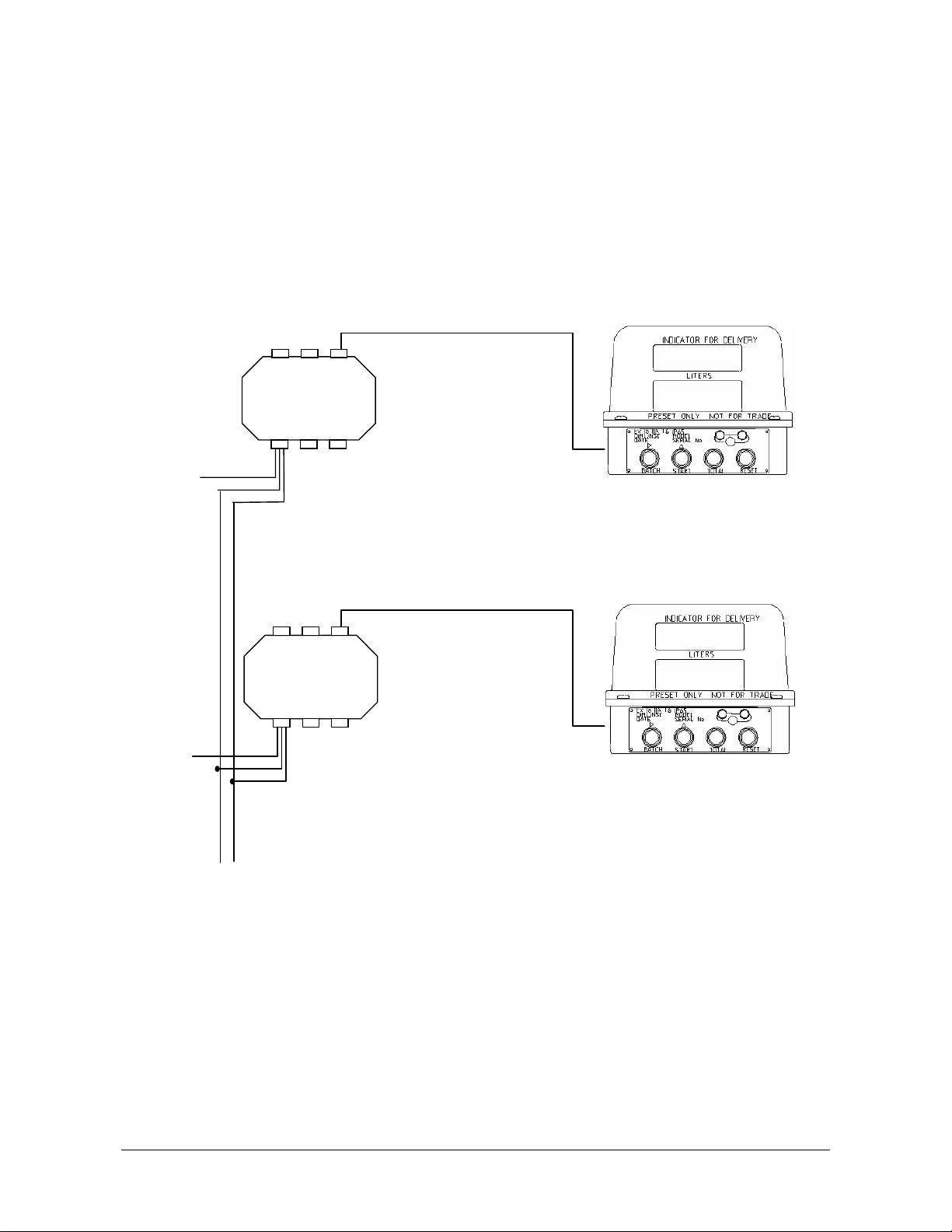
4.8 Connecting Multiple EMH500 registers
More than one EMH500 can be connected in parallel from situations where multiple pumping occurs.
1. Install the register excepting COMS connections as normal
2. Loop the comms channel terminals between the separate power boxes.
3. (ie Register 1 com1 TX terminal to Register 2 com1 TX terminal and so forth)
4. Connect the external comms devices (TouchPC or Printer) as normal to one register.
As an example the following diagram shows two registers connected together
EMH500 Register 2
Power Box
EJB101
Power
2 wire
Pos., Neg.
COM 1
3 wire
TX, RX, Gnd
COM 2
3 wire
TX, RX, Gnd
COM 1 to
external
device
3 wire
TX
,
RX
,
Gnd
COM 2 to
external
device
3 wire
TX
,
RX
,
Gnd
EMH500 Register 1
Power Box
EJB 101
Power
2 wire
Pos., Neg.

TouchStar Americas, Inc. Page 15 of 25
T:\HARDWARE & SUPPORT\TSP Products\EMH Manuals\EMH500 Series Installation Manual 2.1a.doc
5. Calibration Set-up
5.1 Typical Printout
---------------------------SETUP---01.01.22---------------------------
COMPANY NAME ________________ LIQUIP
METER NUMBER_________________ 0120
DATE __________________________ 02/01/1998
DATE_FORMAT__________________ MM/DD/YY
TIME ___________________________ 12:54
K-FACTORS RANGE_______________STANDARD
K0-FACTOR _____________________ 1500.000
OPERATION MODE_______________ NORMAL
PRODUCT TYPE__________________ LPG
S.G. MAN. ENTERED______________ 0.500
TEMPERATURE CONV____________ ENABLED
UNCONVERTED VOL ____________ ENABLED
UNITS __________________________ GALLONS
RESOLUTION____________________ 0.1 G
ACCUM. TOTAL _________________ 00001034.4 G
POWER INTERRUPTS_____________ 000
PULSER INPUT NO._______________ 1
DIR OF ROTATION _______________ ANTICLOCKWISE
SINGLE PULSE IN ________________ DISABLED
REMOTE SG CAL_________________ DISABLED
REMOTE CLK CAL _______________ ENABLED
REMOTE BATCH CAL ____________ ENABLED
PULSE OUTPUT__________________ LOW SPEED
RESET TIMEOUT_________________ 000 SEC
PRODUCT RETURN________________DISABLED
REMOTE RESET__________________ ENABLED
PRESET VOLUME ________________ 0000000 G
RAMP UP________________________ 000 G
RAMP DOWN ____________________ 000 G
FLOW RATE START ______________ 00000 GPM
FLOW RATE MAX________________ 10000 GPM
FLOW RATE STOP________________ 00000 GPM
N/PULSE TIMEOUT_______________ 000 SEC
OVERSHOOT ____________________ 00.0 G
PRINT DELAY ___________________ 00 SEC
AIR BLOW_______________________ 00 SEC
PORT 1__________________________ TOUCH-C,9600,NAC
PORT 2__________________________ BLST PRN, 9600, ACK
INDEX-PORT1 ___________________ YES
INDEX-PORT2 ___________________ YES
DEL.TICK. COPIES _______________ 1,1
SPECIAL DOCKET________________ N/A, N/A
DATA BLOCK____________________ N/A, N/A
SPACE LINES ____________________ N/A, N/A
NEGATIVE ACK__________________ Y, N/A
EMH400 EMULATION_____________ N, N/A
NON-LIN CORRECTN _____________ DISABLED
Fa__00000 GPM Ka-FACTOR__015.0000
Fb__00000 GPM Kb-FACTOR__015.0000
Fc__00000 GPM Kc-FACTOR__015.0000
Fd__00000 GPM Kd-FACTOR__015.0000
Fe__00000 GPM Ke-FACTOR__015.0000
Ff__00000 GPM Kf-FACTOR__015.0000
Fg__00000 GPM Kg-FACTOR__015.0000
Fh__00000 GPM Kh-FACTOR__015.0000
MANAG? – [CONAME] LIQUIP
MANAG? – MeNo0000
CLOCK? – [DATE] 00/00/00
CLOCK? – DD/MM/YY
CLOCK? – [TIME] 00:00:00
KO CAL? – Range ST
KO CAL? – [KO] 1500.0000
MANAG? – ModeNORM
MANAG? – LPG?N
MANAG? – [S.G.]0.0000 or [DENSITY]0.0000
MANAG? – [TEMPERAT] automatically detects probe status
MANAG? – UnconV?N
MANAG? – UNITS L
MANAG? – Rsln 0.1
MANAG? – [AC.TOTAL] 00000000
MANAG? – PInt 000
MANAG? – PulsInp1
MANAG? – DirRot?A
MANAG? – Sinput?N
MANAG? – RemDEN?N
MANAG? – RemCLK?N
MANAG? – RemBAT?N
MANAG? – P/O LO
MANAG? - RsTm000
MANAG? – PRmode?N
MANAG? – RemRES
BATCH? – B00000.0
BATCH? – RmUP 000
BATCH? – RmDwn000
BATCH? – Fup00000
BATCH? – Fmx10000
BATCH? – Fdn00000
BATCH? – TmOut 000
BATCH? – Over 00.0
BATCH? – Delay 00
BATCH? – Blow 00
COMM? – PORT1?N
COMM? – PORT2?N
COMM?N – PORT1?Y – P1 IND?N (printer only)
COMM?N – PORT2?Y – P1 IND?N (printer only)
COMM?N – COPIES 1 (Blaster Printer Only)
COMM?N – SpecialN (Printer Only except Blaster)
COMM?N - DatablkA (Printer Only except Blaster)
COMM?N - Lines00 (Printer Only except Blaster)
COMM?N - NegACK?Y (TouchPC only)
COMM?N - EMH400?Y (TouchPC only)
N-LIN? – Fa00000 + Ka?
N-LIN? – Fa00000 + Kb?
N-LIN? – Fa00000 + Kc?
N-LIN? – Fa00000 + Kd?
N-LIN? – Fa00000 + Ke?
N-LIN? – Fa00000 + Kf?
N-LIN? – Fa00000 + Kg?
N-LIN? – Fa00000 + Kh?
Menu Menu Options

TouchStar Americas, Inc. Page 16 of 25
T:\HARDWARE & SUPPORT\TSP Products\EMH Manuals\EMH500 Series Installation Manual 2.1a.doc
5.2 Setting the Average K-factor (KO CAL)
This mode allows the user to manually set or to automatically calculate the K factor. It is required that a
volume be dispensed into a certified measuring container and that this value then be compared to the
reading on the register.
1 From the delivery mode, press CAL to enter into the main menu.
2 K0 CAL? N, will appear with the cursor flashing on the N. This indicates that this option can be changed.
If you are already in the main menu, toggle through the options by pressing TOTAL until this option is
reached.
3 Press TOTAL to toggle this option to Y (for yes). This allows the user to change the K factor.
4 Press STOP/START to enter this option.
5 XXX.XXXX appears on the display with the cursor flashing on the left most digit.
6 To enter a new K factor manually:-
6.1 The new K-factor to be entered must firstly be calculated.
6.2 The user can change the value of the first digit by pressing TOTAL.
6.3 Press RESET to toggle to the next digit and so on for each digit.
6.4 When the K factor has been set, press STOP/START to save this option.
6.5 Press MODE. The display will now read K0 ACN? N, with the cursor flashing on the N. This
option is asking the user if they want to automatically calculate the K factor. Since the K factor
has already been manually set, leave this option as N (for no).
6.6 Press MODE to return to the Main Menu.
7 To automatically calculate the K factor, follow steps 1 to 5, then:
7.1 Press MODE. The display will now show K0 ACN? N, with the cursor flashing on the N. This
indicates that this option can be changed.
7.2 Press TOTAL to toggle this option to Y (for yes).
7.3 Press STOP/START to enter this option.
The display will now show XXXXX.X with the cursor flashing on the left most digit. This is the volume which
was dispensed in the previous delivery, according to the register. This value may differ to the reading on the
approved test tank. Enter the true value of the delivery according to the reading of the test tank.
7.4 Press TOTAL to set the first digit.
7.5 Press RESET to select the next digit, and so on until the true volume reading has been entered.
7.6 Press STOP/START to enter this value.
The register will now calculate the new K factor. This new K factor will momentarily be displayed, followed
by WAIT, then SAVED, before returning the display to the previously dispensed volume measured by the
register. Note that in this procedure, the user was not asked to perform any calculations.
7.7 Press MODE to return to the Main Menu.
8 Press CAL to return to delivery mode.
9 We recommend that a re-test be done using at least three calibration runs to verify the result. If
recalibration is required, repeat steps 1 to 6 (manual calculation), or steps 1 to 7 (for automatic
calculation).
New K-factor = (Register Reading) ×(Old K-factor)
Measuring Container Reading

TouchStar Americas, Inc. Page 17 of 25
T:\HARDWARE & SUPPORT\TSP Products\EMH Manuals\EMH500 Series Installation Manual 2.1a.doc
6. Connecting a Ticket Printer
Installation and configuring a ticket printer is dependent on the model of the printer. The EMH500 can
support the following printers:
•TM-295
•CTM-290
•TouchStar Blaster Printer.
Most ticket printers are available in +24V only, therefore a voltage doubler will need to be used if run off a
+12V source. All printers have data connections to the register via the Power Junction Box.
Note: Always mount the ticket printer in the cabin.
6.1 Ticket Printer DIP Switch Settings.
There are 3 Ticket Printer models supported by the EMH500’s software; they are the Epson CTM-290, TM-
295 and the TouchStar Blaster. Following are two tabulated listings for the Epson CTM-290 and TM295
printers.
DIP Switch Settings for the TM-295 printer.
Switch Function On Off
1 Data Receive Error Ignored PRINTS”?”
2 Receive Buffer Capacity Data Buffer 35 Bytes DATA BUFFER 512
BYTES
3 Handshaking XON/XOFF DTR/DSR
4 Data Word Length 7 Bits 8 BITS
5 Parity Check Yes NO
6 Parity Selection Even ODD
7
8
Baud Rate Selection Transition
Refer to
Speed Selection
Table Below
9 Pin 6: Reset Signal Used Not Used
10 Pin 25: Reset Signal Used Not Used
TM-295 Transmission Speed.
Transmission Speed Switch 7 Switch 8
1200 bps ON ON
2400 bps OFF ON
4800 bps ON OFF
9600 bps OFF OFF

TouchStar Americas, Inc. Page 18 of 25
T:\HARDWARE & SUPPORT\TSP Products\EMH Manuals\EMH500 Series Installation Manual 2.1a.doc
TM-295 Default DIP Switch Settings. (1200 Baud)
DIP Switch Settings for the CTM-290 printer.
Switch On Off
1
2
3
International Character
Refer to
Set Selection.
Table Below
4 7 bit length 8 bit length
5 Parity check enabled Parity check disabled
6 Even Parity Odd Parity
7
8
9
Baud Rate
Refer to
Selection
Table Below
10 Not Used Always OFF
CTM-290 International Character Set Selection.
Country Switch 1 Switch 2 Switch 3
U.S.A ON ON ON
FRANCE OFF ON ON
GERMANY ON OFF ON
U.K. OFF OFF ON
DENMARK ON ON OFF
SWEDEN OFF ON OFF
ITALY ON OFF OFF
SPAIN OFF OFF OFF
CTM-290 Baud Rate Selection.
Baud Rate (BPS) Switch 7 Switch 8 Switch 9
110 ON ON ON
150 OFF ON ON
300 ON OFF ON
600 OFF OFF ON
1200 ON ON OFF
2400 OFF ON OFF
4800 ON OFF OFF
9600 OFF OFF OFF
CTM-290 Default DIP Switch Settings. (1200 Baud/UK Character Set)

TouchStar Americas, Inc. Page 19 of 25
T:\HARDWARE & SUPPORT\TSP Products\EMH Manuals\EMH500 Series Installation Manual 2.1a.doc
Check that your Ticket Printer has an ink ribbon fitted.
Set up the comm ports and the printer type in the register (refer to software).
6.2 Installing the TouchStar Blaster Printer
The TouchStar Blaster Printer has no DIP switches therefore once it is wired up, you only have to setup the
register (refer to Software Settings Reference Manual).
Note: Always set the EMH500 to 9600 baud rate when using the TouchStar Blaster Printer.
6.3 Checking the Operation of the Ticket Printer
Supply power to the Register and Ticket Printer, checking for the GREEN (POWER) LED on the printer.
Press the RELEASE button and note that the GREEN (RELEASE) LED appears. Insert your ticket so that
the top of the top line is aligned with the arrow on the side of the printer.
Note: If the ticket is inserted correctly, the RED (PAPER OUT) LED will go out but if the RED LED remains
ON, remove and insert ticket again until NO RED LED is visible.
Perform a delivery run or simply rotate the Register by hand. Print a Delivery Ticket by pressing RESET not
sooner than 6 seconds after the end of the delivery.
Press the RELEASE button on the ticket printer to release the ticket from the printer.
6.4 Connecting multiple registers to one printer.
Connect wires in the following way:
•EMH/EJB’s transmit wires joined together to the receive input of the printer,
•EMH/EJB’s receive wires joined together to the transmit output of the printer,
•EMH/EJB’s ground wires joined together to the ground input of the printer,
•Do NOT join shields of communication cables – each individual cable must have its shield connected to
the ground inside the EJB junction box ONLY.

TouchStar Americas, Inc. Page 20 of 25
T:\HARDWARE & SUPPORT\TSP Products\EMH Manuals\EMH500 Series Installation Manual 2.1a.doc
7. Various DIP Switch Settings
7.1 EMH500 Mainboard DIP switch specifications.
The DIP switches are located under the plastic hood of the register head and approximately in the centre of
the main board. The register will only read the new settings immediately after a power-up.
Dip Switch No. Function
Sw1 By setting the switch to ON, it will ENABLE the erasing option for the internal
software settings. Immediately following power on the display will read ‘ERASE?N’,
press TOTAL and then STOP/START to erase all software settings and re initialise
with default settings. The register will then read “ERASE!”, and scroll “memory
cleared – restart register”. Power the register off then back on again. The “data error”
message will be displayed, to reset the EMH500 to default values press the CAL
button.
Sw2 By setting the switch to ON, it will DISABLE the automatic compensation of
resistance of the temperature probe leads. You have to restart the register after
switching it. The register will then require manual zero-adjustment of temperature
reading. It helps using temp. probe with two wires only, or when resistance of leads
is higher than 2.5 Ohms.
Sw3 N/A
Sw4 N/A
This table is for the EMH 500 Rev D Mainboard
Note: Other EMH 500 main PCB marked as below has the following DIP switch settings
Rev 0: Dip Switch 2 for erasing memory
Rev 1: Dip Switch 1 for erasing memory
Dip Switch 4 for supplying power to the internal EMH500 pulser board (Opt PCB). You must
set this option to OFF to connect a ERP100 remote pulser to the EMH500.
Rev 2: same as Rev 1
Rev 3: same as Rev 1
Rev 4(D): Dip Switch 4 unused
Rev 5: same as Rev 4
Table of contents


