TEC MA-600 Series User manual

PRINTED IN JAPAN
TEC Electronic Cash Register
MA-600 SERIES
Document No. EO18-11006A
Original Dec., 2005
(Revised Dec., 2006)
Maintenance Manual
NOTE:
Model names that end with “-R” are RoHS compliant models. If “-R” is not
attached, that model is non RoHS compliant.
Never install non RoHS compliant optional equipment or parts on a RoHS
compliant machine which is supposed to be used in the countries that enforce
the RoHS directive, as doing this is legally prohibited.

WARNING!
Follow all manual instructions. Failure to do so could create safety hazards such as fire or
electrocution.
NOTES:
1. Manual instructions must be followed when installing option kits or adding cables to avoid system
failures and to insure proper performance and operation.
2. Failure to follow manual instructions or any unauthorized modification, substitution or change to
this product will void the limited product warranty.

EO18-11006A
TABLE OF CONTENTS
Page
1. UNPACKING ..............................................................................................................1- 1
1.1 Procedure........................................................................................................................1- 1
1.2 Checks.............................................................................................................................1- 1
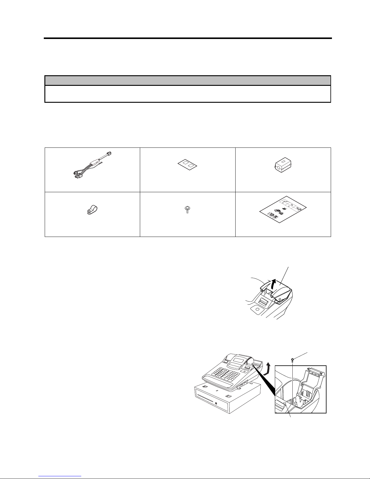
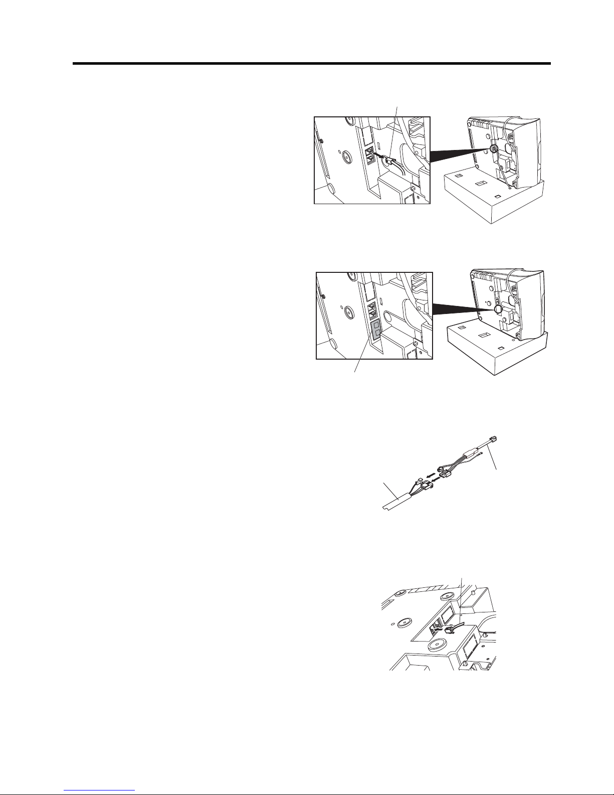
2. INSTALLATION PROCEDURE FOR OPTIONAL EQUIPMENT................................2- 1
2.1 KRDC-600-QM-R (for QP model only) ............................................................................2- 1
3. DIAGNOSTIC TEST OPERATION.............................................................................3- 1
3.1 Diagnostic Test Operation List ........................................................................................3- 1
3.2 Print Test (“H” & All Characters)......................................................................................3- 2
3.3 Display Test.....................................................................................................................3- 3
3.4 ROM Test........................................................................................................................3- 4
3.5 RAM Test.........................................................................................................................3- 5
3.6 Print Test (“H”-consecutive).............................................................................................3- 6
3.7 RS-232C Loop Back Test................................................................................................3- 7
3.8 USB Test.........................................................................................................................3- 8
3.9 Keyboard Test.................................................................................................................3- 9
3.10 Drawer Open Test ..........................................................................................................3-10
3.11 Thermal Printer Test.......................................................................................................3-11
3.12 LCD Test ........................................................................................................................3-12
3.13 Simplified RAM Test.......................................................................................................3-13
3.14 RAM Installation Test .....................................................................................................3-14
3.15 Key Input Count Reading ...............................................................................................3-15
3.16 Network Controller Information Read .............................................................................3-16
3.16 Number of Print Lines Reading ......................................................................................3-16
3.17 General Test...................................................................................................................3-17
3.18 Print Density Setting.......................................................................................................3-19
4. PERIODIC MAINTENANCE .......................................................................................4- 1
5. TROUBLESHOOTING................................................................................................5- 1

EO18-11006A
CAUTION!
1. This manual may not be copied in whole or in part without prior written permission of TOSHIBA
TEC.
2. The contents of this manual may be changed without notification.
3. Please refer to your local Authorised Service representative with regard to any queries you may
have in this manual.
Copyright © 2005
by TOSHIBA TEC CORPORATION
A
ll Rights Reserved
570 Ohito, Izunokuni-shi, Shizuoka-ken, JAPAN
Pictures and figures of the QP model are used in this manual for instance.
Page
6. MAIN UNIT REPLACEMENT .....................................................................................6- 1
6.1 Removing the Top Cover Ass’y.......................................................................................6- 1
6.2 Replacing the MAIN PC Board Ass’y ..............................................................................6- 3
6.3 Replacing the Power PC Board Ass’y.............................................................................6- 5
6.4 Replacing the LCD Ass’y.................................................................................................6- 6
6.5 Replacing the FIU PC Board Ass’y..................................................................................6- 7
6.6 Replacing the RIU Unit...................................................................................................6-10
6.7 Replacing the KBIU PC Board Ass’y..............................................................................6-12
6.8 Replacing the Keyboard Unit..........................................................................................6-14
6.9 Replacing the Receipt Printer Unit .................................................................................6-16
6.10 Replacing the Journal Printer Unit..................................................................................6-18
6.11 Replacing the Platen Roller Ass’y ..................................................................................6-20

1. UNPACKING EO18-11006A
1.1 Procedure
1- 1
1. UNPACKING
1.1 Procedure
CAUTION!
1. When newly setting up the MA-600, plug the power cord to charge the ECR for 48 hours or more.
2. When using the MA-600 not electrified for 1 month or more, plug the power cord to charge the ECR
for 48 hours or more and then perform a RAM clear, resulting that the ECR performs normally.
1) Open the carton.
2) Take the accessories out of the carton.
3) Take out the ECR and remove the pads.
4) Place the ECR on a level surface.
1.2 Checks
1) Check for the damage or scratches on the machine.
2) Confirm that none of the accessories are missing.
NOTE: Keep that original cartons and pads for future transportation of the ECR.

2. INSTALLATION PROCEDURE FOR OPTIONAL EQUIPMENT EO18-11006A
2.1 KRDC-600-QM-R (for QP model only)
2- 1
2. INSTALLATION PROCEDURE FOR OPTIONAL
EQUIPMENT
WARNING!
Be sure to unplug the power cord before installing any optional equipment.
2.1 KRDC-600-QM-R (for QP model only)
This kit is used for connecting the RD-G8-C-QM-R Remote Drawer to the MA-600 series.
• Packing List
DRW1 DRW2
Remote Drawer Harness (1 pc.) Connector Label (1 pc.) Ferrite Core (1 pc.)
KRDC-600-QM-R Installation Manual
DRDRW1
W1DR
DRW2
W2
Abcdefghijklmnopqrstuvwxyzabcdefghijklmnopqrstuvwxyz
abcdefghijklmnopqrstuvwxyz.
Abcdefghijklmnopqrstuvwxyzabcdefghijklmnopqrstuvwxyz
abcdefghijklmnopqrstuvwxyz.
Abcdefghijklmnopqrstuvwxyzabcdefghijklmnopqrstuvwxyz
abcdefghijklmnopqrstuvwxyz.
Abcdefghijklmnopqrstuvwxyzabcdefghijklmnopqrstuvwxyz.
KRDC-600-QM-RInstallationManual
DR
DRW1
W1
DR
DRW2
W2
Abcdefghijklmnopqrstuvwxyzabcdefghijklmnopqrstuvwxyz
abcdefghijklmnopqrstuvwxyz.
Abcdefghijklmnopqrstuvwxyzabcdefghijklmnopqrstuvwxyz
abcdefghijklmnopqrstuvwxyz.
Abcdefghijklmnopqrstuvwxyzabcdefghijklmnopqrstuvwxyz
abcdefghijklmnopqrstuvwxyz.
Abcdefghijklmnopqrstuvwxyzabcdefghijklmnopqrstuvwxyz.
Cable Clamp (1 pc.) Screw (1 pc.) Installation Manual (1 copy)
• Installation Procedure
1) Remove the journal cover.
2) Push the release button to rise the journal paper
retainer, remove the screw which secures the
ECR onto the drawer, then separate them by
moving the ECR backward.
Journal Cover
Screw
It is
not necessary to remove this
screw secures the top cover.

2. INSTALLATION PROCEDURE FOR OPTIONAL EQUIPMENT EO18-11006A
2.1 KRDC-600-QM-R (for QP model only)
2- 2
3) Disconnect the drawer cable from the bottom of
the ECR.
4) Attach the connector label beside the drawer
connector as shown in the figure.
5) Connect the remote drawer harness to the
remote drawer cable.
6) Insert the modular connector of the remote
drawer harness into the DRW2 connector.
Drawer Cable
Remote Drawer Cable
Remote Drawer Harness
DRW1 DRW2
Connector Label
Modular Connector
DRW2

2. INSTALLATION PROCEDURE FOR OPTIONAL EQUIPMENT EO18-11006A
2.1 KRDC-600-QM-R (for QP model only)
2- 3
7) Secure the remote drawer harness onto the
bottom of the ECR with the option cable clamp
and screw as shown in the figure. At this time,
secure the earth wire of the remote drawer
harness together.
8) Insert the drawer cable which was disconnected
in Step 3 into the DRW1 connector, then
reassemble in the reverse order of removal.
9) Attach the ferrite core to the remote drawer cable
on the drawer side.
10) Perform the System Option Programming,
Address No. 27.
Cable Clamp
Screw (option)
Earth Wire
Ferrite Core
Remote Drawer

3. DIAGNOSTIC TEST OPERATION EO18-11006A
3.1 Diagnostic Test Operation List
3- 1
3. DIAGNOSTIC TEST OPERATION
3.1 Diagnostic Test Operation List
[X] = [@/FOR]
No. Diagnostic Function Key Operation
1 Print Test (“H” & All characters) 80 [X] 1 [AT/TL]
2 Display Test 80 [X] 2 [AT/TL]
3 ROM Test 80 [X] 3 [AT/TL]
4 RAM Test 80 [X] 4 [AT/TL]
5 Print Test (“H”- consecutive) 80 [X] 5 [AT/TL]
6 RS-232C Loop Back Test 80 [X] 6 [ST] n [AT/TL]
7 USB Test 80 [X] 13 [AT/TL]
8 Keyboard Test 80 [X] 14 [AT/TL]
9 Drawer Open Test 80 [X] 15 [AT/TL]
10 Thermal Print Test 80 [X] 17 [AT/TL]
11 LCD Test 80 [X] 19 [AT/TL]
12 Simplified RAM Test 80 [X] 30 [AT/TL]
13 RAM Installation Test 80 [X] 31 [AT/TL]
14 Key Input Count Reading 96 [X] [AT/TL]
15 Number of Print Lines Reading 98 [X] [AT/TL]
16 General Test 80 [X] 92 [AT/TL]
17 Print Tone Setting 80 [X] 17 [ST] n [AT/TL]

3. DIAGNOSTIC TEST OPERATION EO18-11006A
3.2 Print Test (“H” & All Characters)
3- 2
3.2 Print Test (“H” & All Characters)
(1) Contents
A print test is performed. This test prints “H”s and all characters.
(2) Operation
Mode Lock: BLIND
Key Operation: 80 [X] (or [@/FOR]) 1 [AT/TL]
(3) Print Format
(4) Display
No function
(5) Quit
The test ends by pressing the [ITEM CORR] key.
NOTES:
1. In the Receipt OFF mode, the print data is printed only on the journal.
2. When the power is turned OFF during the test, it will be resumed at the power on time unless the Mode Lock
position is “BLIND”.
3. When the paper is set on the remote slip printer, the test is also performed on this printer.
10-31-2005 MON #0
P80
DIAG 01
HHHHHHHHHHHHHHHHHHHHHHHHHHHHHHHH
:
HHHHHHHHHHHHHHHHHHHHHHHHHHHHHHHH
HHHHHHHHHHHHHHHH
:
HHHHHHHHHHHHHHHH
!!!!!!!!!!!!!!!!!!!!!!!!!!!!!!!!
‰‰‰‰‰‰‰‰‰‰‰‰‰‰‰‰‰‰‰‰‰‰‰‰‰‰‰‰‰‰‰‰
################################
:
DDDDDDDDDDDDDDDDDDDDDDDDDDDDDDDD
0004 15:40TM
One-byte “H”s are printed consecutively.
(32 characters by 10 lines)
Two-byte “H”s are printed consecutively.
(16 characters by 10 lines)
Each character codes are printed by line.
(32 characters/line)
Store Name Logo

3. DIAGNOSTIC TEST OPERATION EO18-11006A
3.3 Display Test
3- 3
3.3 Display Test
(1) Contents
A display test is performed on the LCD display and the 7-segment display at the same time.
First, all dots light. When the [ITEM CORR] or [ALL VOID] (QP model only) key is pressed, the characters
start to scroll to the left.
(2) Operation
Mode Lock: BLIND
Key Operation: 80 [X] (or [@/FOR]) 2 [AT/TL]
(3) Print Format
(4) Display
• LCD display
U! “ # $ % & ‘ ( ) ••••••••U(Uindicates a space.)
The scrolling characters are displayed in the four lines as well.
• 7-segment display
0 . 1 2 3 4 ••••9 r – o P E U(Uindicates a space.)
(5) Quit
The test pauses when the [ITEM CORR] key is pressed and a receipt is issued.
NOTES:
1. The above characters are repeatedly displayed by scrolling to the left until the [ITEM CORR] key is pressed.
2. When the power is turned OFF during the test, the test will be resumed at the power on time unless the
Mode Lock position is “BLIND”.
3. The same test is performed on both Customer Display and Operator Display. (7-segment display)
4. In the Receipt OFF mode, the print data is printed only on the journal.
5. Before displaying the scrolling characters, the display lights all dots (on the LCD display), all segments (on
the 7-segment display), all triangle marks, and all periods (on the 7-segment display) until the [ITEM CORR]
key is pressed.
10-31-2005 MON #0
P80
DIAG 02
0005 15:41TM
Store Name Logo

3. DIAGNOSTIC TEST OPERATION EO18-11006A
3.4 ROM Test
3- 4
3.4 ROM Test
(1) Contents
A ROM test is performed. This test automatically prints the checksum of the ROM.
(2) Operation
Mode Lock: BLIND
Key Operation: 80 [X] (or [@/FOR]) 3 [AT/TL]
(3) Print Format
(4) Display
No function
(5) Quit
The receipt is issued, then the test ends automatically.
NOTE: In the Receipt OFF mode, the print data is printed only on the journal.
10-31-2005 MON #0
P80
DIAG 03
MA-600-QP V.999.999 #00Z
BOOT SUM V.999.999 9999
OS/APL SUM 9999
ALL SUM 9999
Copyright(C) 2005
TOSHIBA TEC CORPORATION
All Rights Reserved.
0006 15:42TM
Model name, Program version, ROM version
Boot area: Version, Checksum 000000H to 00FFFFH
OS/APL area: Checksum 010000H to 1FFFFFH
A
ll ROM areas: Checksum 000000H to 1FFFFFH
Store Name Logo

3. DIAGNOSTIC TEST OPERATION EO18-11006A
3.5 RAM Test
3- 5
3.5 RAM Test
(1) Contents
A RAM test is performed.
The program writes certain data into each RAM chip and checks if the written data is read normally.
(2) Operation
Mode Lock: BLIND
Key Operation: 80 [X] (or [@/FOR]) 4 [AT/TL]
(3) Print format
(4) Display
No function
(5) Quit
The receipt is issued, then the test ends automatically.
NOTES:
1. The test checks the RAM and the result is printed.
2. The RAM is checked in unit of 1 byte.
3. In the Receipt OFF mode, the print data is printed only on the journal.
4. In the test, a read/write test is performed for all RAM areas with 8 patterns of 0x01, 0x02, 0x04, 0x08, 0x10,
0x20, 0x40, and 0x80.
OK: Normal termination
NG: Error
10-31-2005 MON #0
P80
DIAG 04
01000000H–0103FFFFH OK
0007 15:43TM
Store Name Logo

3. DIAGNOSTIC TEST OPERATION EO18-11006A
3.6 Print Test (“H”-consecutive)
3- 6
3.6 Print Test (“H”-consecutive)
(1) Contents
This test prints the letter “H” repeatedly.
(2) Operation
Mode Lock: BLIND
Key Operation: 80 [X] (or [@/FOR]) 5 [AT/TL]
(3) Print format
(4) Display
No function
(5) Quit
The test ends by pressing the [ITEM CORR] key.
NOTES:
1. In the Receipt OFF mode, the print data is printed only on the journal.
2. When the power is turned OFF during the test, it will be resumed at the power on time unless the Mode Lock
position is “BLIND”.
3. When the paper is set on the remote slip printer, the test is also performed on this printer.
10-31-2005 MON #0
P80
DIAG 05
HHHHHHHHHHHHHHH
:
HHHHHHHHHHHHHHHH
HHHHHHHHHHHHHHHHHHHHHHHHHHHHHHHH
:
HHHHHHHHHHHHHHHHHHHHHHHHHHHHHHHH
0008 15:44TM
One-byte “H”s are printed consecutively.
Two-byte “H”s are printed consecutively.
(16 characters by 20 lines)
Store Name Logo

3. DIAGNOSTIC TEST OPERATION EO18-11006A
3.7 RS-232C Loop Back Test
3- 7
3.7 RS-232C Loop Back Test
(1) Contents
A Loop back test for the RS-232C interface line is performed.
Before starting the test, connect a loop back connector to the COM port to be tested.
(2) Operation
Mode Lock: BLIND
Key Operation: 80 [X] (or [@/FOR]) 6 [ST] n [AT/TL]
COM port number: 1 (COM 1)
(3) Print format
(4) Display
(5) Quit
The test ends by pressing the [ITEM CORR] key.
NOTES:
1. In the Receipt OFF mode, the print data is printed only on the journal.
2. When the power is turned OFF during the test, it will be resumed at the power on time unless the Mode Lock
position is “BLIND”.
3. The wiring pattern of the loop back connector is as shown below.
NC 1
RXD 2
TXD 3
DTR 4
GND 5
DSR 6
RTS 7
CTS 8
NC 9
D 1 – 6 **** * ****
Test count (0000 to 9999)
Status
0: Normal termination
1: Data receive error
2: Parity, overrun, or framing error
3: Timeout error
4: DTR/DSR error or RTS/CTS erro
r
Error count (0000 to 9999)
10-10-2003 FRI #0
P80
DIAG 06
CH1 COMM TEST
9999/9999
0009 15:45TM
Store Name Logo
Error count/Test count

3. DIAGNOSTIC TEST OPERATION EO18-11006A
3.8 USB Test
3- 8
3.8 USB Test
(1) Contents
A USB connection test is performed. Before starting the test, connect a PC to the ECR with a USB cable.
(2) Operation
Mode Lock: BLIND
Key Operation: 80 [X] (or [@/FOR]) 13 [AT/TL]
(3) Print format
(4) Display
No function
(5) Quit
The receipt is issued, then the test ends automatically.
NOTE: In the Receipt OFF mode, the print data is printed only on the journal.
10-31-2005 MON #0
P80
DIAG 13
USB CONNECT OK
0010 15:46TM
Store Name Logo
OK: Normal connection
NG: Error

3. DIAGNOSTIC TEST OPERATION EO18-11006A
3.9 Keyboard Test
3- 9
3.9 Keyboard Test
(1) Contents
The sum of the hard key codes entered through the keyboard is displayed in hex.
Also, the currently entered cashier code and the mode key position is displayed.
(2) Operation
Mode Lock: BLIND
Key Operation: 80 [X] (or [@/FOR]) 14 [AT/TL] [Key to be tested] [AT/TL] [AT/TL]
(3) Print format
(4) Display
• LCD display
• 7-segment display
(5) Quit
The test ends by pressing the [AT/TL] key twice.
D 1 – 1 4 * * * * * * * Sum of the hard key codes (Hex.) (0000H to FFFFH)
• The sum of the pressed hard key codes is displayed
in hex.
• Even if the same key is pressed twice or more, its
hard key code is counted only once.
00 fixed (not used)
Mode key position (1 to 8)
The numbers from 1 to 8 represent the mode lock key positions as
follows:
1: SET 2: LOCK 3: REG 4: X
5: MGR 6:
7: Z 8: BLIND
10-31-2005 MON #0
P80
DIAG 14
0012 15:48TM
Store Name Logo
* * * * * * *
Sum of the hard key codes (Hex.) (0000H to FFFFH)
Mode key position (1 to 8)
00 fixed (not used)

3. DIAGNOSTIC TEST OPERATION EO18-11006A
3.10 Drawer Open Test
3-10
3.10 Drawer Open Test
(1) Contents
All drawers which are connected to the ECR are opened.
(2) Operation
Mode Lock: BLIND
Key Operation: 80 [X] (or [@/FOR]) 15 [AT/TL]
(3) Print format
(4) Display
• LCD display (2nd line)
• 7-segment display
∗When a drawer is opened, the corresponding drawer No. is displayed.
∗The drawer No. goes off when the drawer is closed.
∗The drawers are opened in the order of drawer 1 and drawer 2 at one second interval.
(5) Quit
The test ends by pressing the [ITEM CORR] key or by closing the drawer.
NOTES:
1. When the power is turned OFF during the test, it will be resumed at the power on time unless the Mode Lock
position is “BLIND”.
2. When no drawer is connected or the connected drawer does not support the drawer compulsory function,
the drawer status is always “Open” regardless of the actual drawer status.
10-31-2005 MON #0
P80
DIAG 15
0012 15:48TM
Store Name Logo
Drawer No. 2
Drawer No. 1
D 1
–
1 5 1 2
1 2
Drawer No. 2
Drawer No. 1

3. DIAGNOSTIC TEST OPERATION EO18-11006A
3.11 Thermal Print Test
3-11
3.11 Thermal Print Test
(1) Contents
This test checks the status of the thermal printer which is installed into the ECR. If an error is detected, the
corresponding error No. is displayed on the 7-segment display. Generally the test is performed after the
printer is replaced.
(2) Operation
Mode Lock: BLIND
Key Operation: 80 [X] (or [@/FOR]) 17 [AT/TL]
(3) Print format
(4) Display
• 7-segment display
When an error was detected, the error No. is displayed.
Error Name Error No.
Head temperature error (Receipt printer) 1
Head temperature error (Journal printer) 2
Head voltage error (both of Receipt and Journal printers) 3
Receipt cover open error 4
Journal head open error 5
Receipt end error 6
Journal end error 7
(When the error in the above table was not detected, the corresponding Error No. is blank on the display.)
(5) Quit
The test ends by pressing the [ITEM CORR] key.
NOTES:
1. The test should be performed when the printer is in normal condition.
2. When the Error No. 1 to No. 3 are displayed, first power off the ECR and replace the printer or the Main PC
board.
10-10-2003 FRI #0
P80
DIAG 17
0012 15:48TM
Store Name Logo
12345678
Error No. (See the table below.)

3. DIAGNOSTIC TEST OPERATION EO18-11006A
3.12 LCD Test
3-12
3.12 LCD Test
(1) Contents
This test checks the dots and the backlight of the LCD display.
(2) Operation
Mode Lock: BLIND
Key Operation: 80 [X] (or [@/FOR]) 19 [AT/TL]
(3) Print format
(4) Display
Dots in the odd columns are displayed. Whenever the [ITEM CORR] key is pressed, dots in the even
columns, dots in the odd lines, dots in the even lines, all dots, on-off action of the backlight, and all reversed
dots are displayed in turn.
(5) Quit
After all reversed dots are displayed, the test ends by pressing the [ITEM CORR] key.
NOTE: In the Receipt OFF mode, the print data is printed only on the journal.
10-31-2005 MON #0
P80
DIAG 19
0012 15:48TM
Store Name Logo
Other manuals for MA-600 Series
2
Table of contents
Other TEC Cash Register manuals

TEC
TEC MA-156-1 SERIES User manual

TEC
TEC FS-2600-1 SERIES User manual

TEC
TEC MA-136 User manual

TEC
TEC MA-215 User manual

TEC
TEC MA-1190 User manual

TEC
TEC FS-2600-1 SERIES User manual

TEC
TEC TEC MA-1300 User manual

TEC
TEC TEC MA-71 User manual

TEC
TEC TEC MA-1040-100 Series User manual

TEC
TEC MA-600 Series User manual

TEC
TEC TEC MA-1450-1 SERIES User manual

TEC
TEC MA-1650-4 Series Owner's manual

TEC
TEC MA-55 User manual

TEC
TEC TEC MA-1700 User manual

TEC
TEC MA-216 User manual

TEC
TEC TEC EO1-11115 User manual

TEC
TEC MA-1595-1 SERIES User manual

TEC
TEC MA-191 User manual

TEC
TEC TEC FDS-30 User manual

TEC
TEC MA-516-100 Series User manual