TouchTronics Invisilok - M115 User manual
NST13308-M115-02_A ◄► 2021-06-23 ◄► Page 1
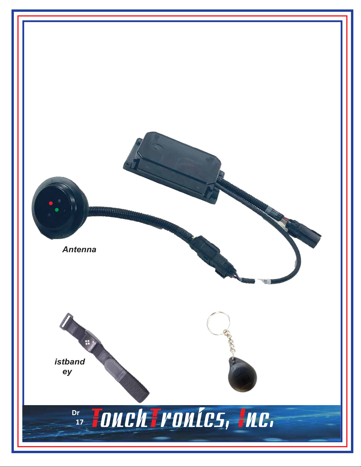
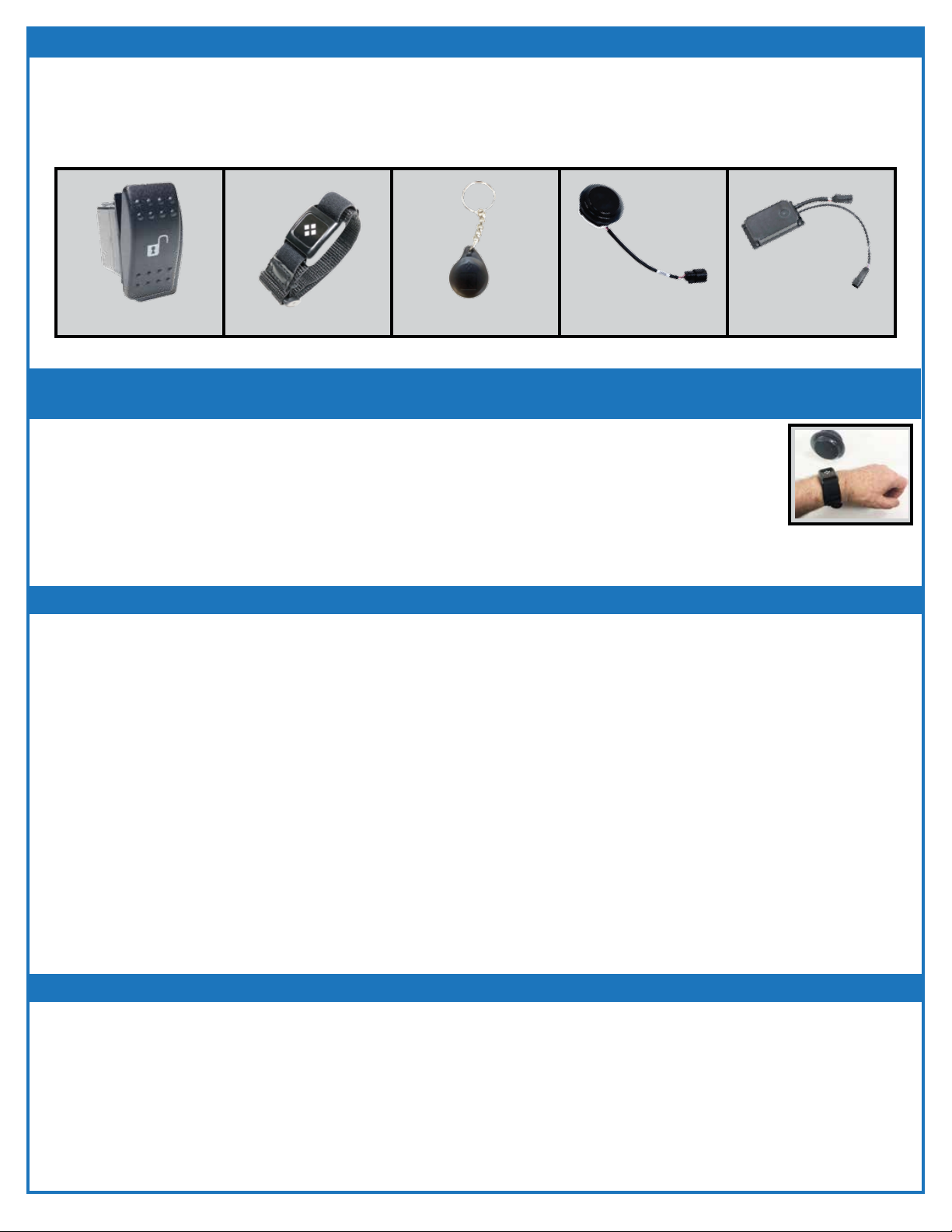
Invisilok - M115
Reader with Remote Antenna
57315 Nagy Dr
Elkhart, IN 46517
800-294-2570
574-294-2570
www.touchtronics.com
Remote Antenna
Reader
Wristband
Key
for a
Keyless Security System for Solenoids
Keychain
Key
NST13308-M115-02_A ◄► 2021-06-23 ◄► Page 2
OPERATION
USING A WRISTBAND KEY OR KEYCHAIN TAG
Present (swipe) Wristband Key or Keychain Key to Remote Antenna.
Wristband Key or Keychain Key should be swiped within 3-4 inches of antenna.
• Door unlocks.
• After six (6) seconds, the door automatically re-locks whether it is open or closed.
• The Red LED on the antenna flashes twice and the Green LED turns ON for 6-seconds.
Note: After a Wristband Key or Keychain Key has been swiped three (3) times in succession,
the system will not allow another swipe for 20 seconds.
USING A SWITCH
Press and release switch located near door to be unlocked (switch is momentary switch).
• Door should unlock immediately.
• After six (6) seconds, the door will automatically re-lock whether it is opened or closed.
• The Red LED on the antenna flashes once and the Green LED turns ON for 6-seconds.
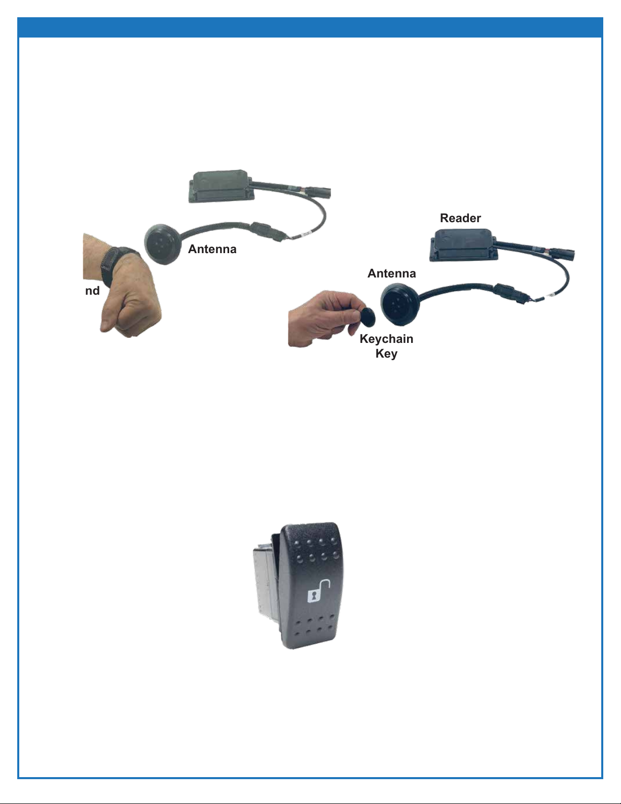
Switch shipped with each kit
Reader
Antenna
Wristband
Key
Keychain
Key
Reader
Antenna
NST13308-M115-02_A ◄► 2021-06-23 ◄► Page 3
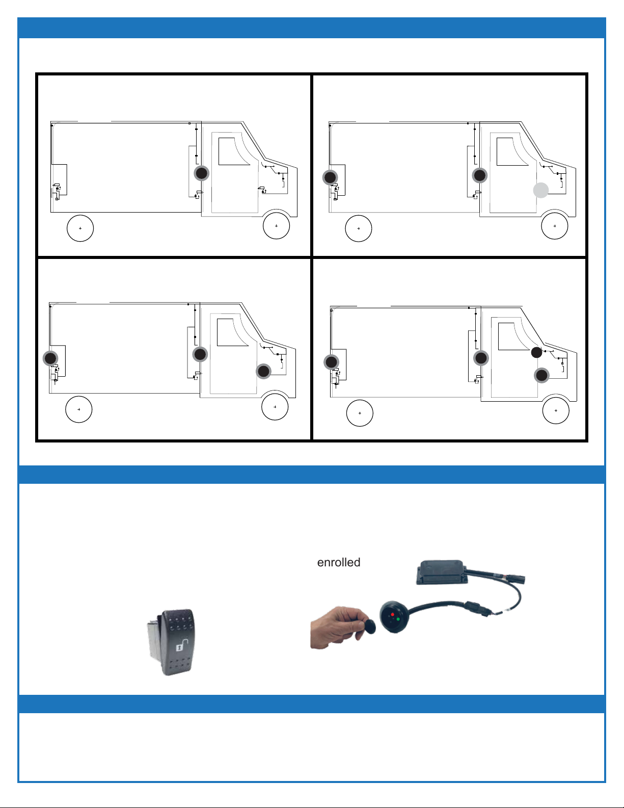
SYSTEM DIAGRAM
This Keyless Entry System can be set up with 1 to 4 Nodes
4 Nodes
Curbside, Driver Side, Bulkhead and Rear Doors
SWITCHES
Curbside View
3 Nodes
Curbside, Bulkhead and Rear Doors
SWITCHES
Curbside View
SWITCHES
Curbside View
2 Nodes
Bulkhead or Curbside and Rear Doors
Antenna
Antenna
SWITCHES
Curbside View
1 Node
Bulkhead Door
Curbside
Antenna
Antenna
Antenna
M115-R1 M115-R2
M115-R3 M115-R4
Antenna
Antenna
(Driver Side)
Antenna
Antenna
Antenna
Antenna
Antenna
Note Tags can ONLY be enrolled at Master Node antenna location
Press switch at Master Node and hold for 10 seconds.
- Red LED on antenna flashes twice.
- All tags are unenrolled.
Press switch at Master Node location five times within 5 seconds.
- Antenna Red LED flashes for 20 seconds.
During this flash time, swipe tag at antenna.
- Antenna Red LED double flashes indicting tag enrolled
WRISTBAND KEY or KEYCHAIN KEY ENROLLMENT
WRISTBAND KEY or KEYCHAIN KEY UNENROLLMENT
Curbside Switch
Wristband Key or Keychain Key swipe at antenna
X
NST13308-M115-02_A ◄► 2021-06-23 ◄► Page 4
INSTALLATION
1. Identify the location of the remote antenna on the exterior of the truck, with the exception of the
bulkhead antenna. The bulkhead antenna is trypically installed on the cab side of the partition wall
between the cargo and cab.
2. The antenna should be placed in a location that is about 36-48” off the ground or floor and one that
is easy to access when swiping with the Wristband Key or Keychain Key.
3. The antenna range is 3-4” when using the Wristband Key or Keychain Key to unlock a door.
4, Drill a 2.5” hole in the truck body or partition wall.
5. Install the gasket onto the remote antenna as it is used to seal the antenna hole.
6. Insert the remote antenna into the opening, gasket on the exterior, and secure using the large nut.
It should be tight enough to prevent water leaking into the truck.
7. Within 36”, identify a mounting location for the reader. This should be in an area that is easy to
access for service and is not exposed to the elements.
8. An extension harness is available if the mounting distance is more than 36””
9. Install the switch at the Master Node location. It unlocks the door and auto relocks the same as a
key swiping the antenna. Each reader can be connected with a switch.
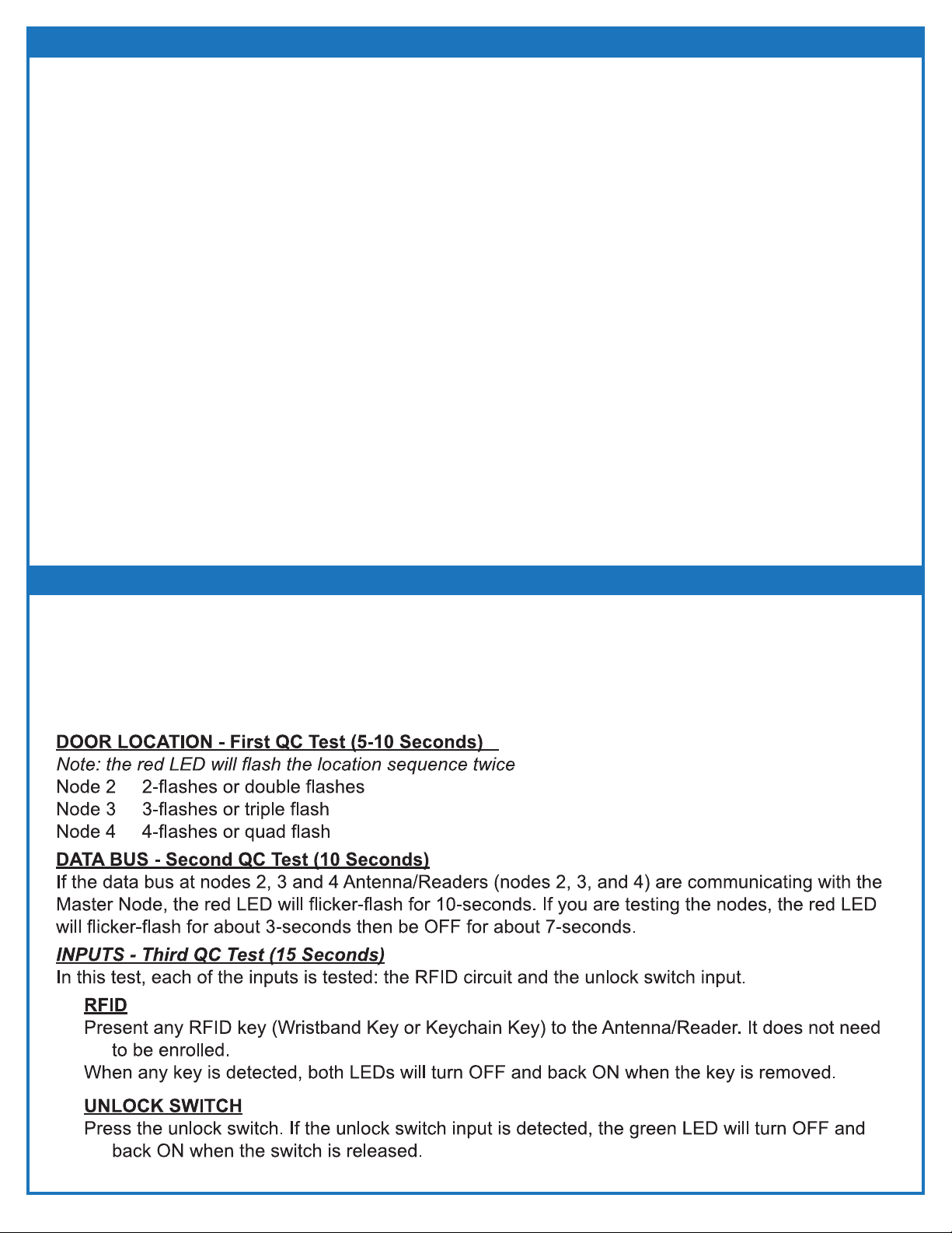
MOD-QC TEST INPUTS - ALL DOORS SHOULD BE CLOSED
Any time the Antenna/Reader is powered-up, the Mod-QC Test is executed and takes about
30-seconds. The red and green status LEDs emit a series of flashes which indicate the status of the
inputs to the Antenna/Reader. The Mod-QC Test interrogates the Antenna/Reader location inputs, the
data bus input and the inputs from the unlock switch and the RFID circuit. The Master Node controls
ALL of the data traffic in the keyless system.
NST13308-M115-02_A ◄► 2021-06-23 ◄► Page 5
TROUBLESHOOTING - KEYLESS ENTRY
Possible Cause #2: The Wristband Key or Keychain Key is Damaged or Defective
Actions ToTake:
• If the door unlocks using the switch but will not unlock with the Wristband Key or the Keychain Key, remove power to the
Antenna/Reader.
• Present the Wristband Key or Keychain Key.
- If is is not detected at the third Mod QC test, the Wristband Key or Keychain Key is defective.
• Replace the Wristband Key or Keychain Key and enroll the new Wristband Key or Keychain Key into the Truck using the Master
Key.
Actions ToTake:
• Unplug the reader from the wire harness and then reconnect it.
• Observe the QC test.
- Location code flashes twice.
- Data Bus operation is tested. If the data bus is present, the Red LED flicker flashes for 10-seconds (if the antenna is at the
Master Node, the flicker flash is a short burst).
- Input check - Both LEDs turn ON solid for 15-seconds to check the reader RFID circuit.
• Swipe a known “good” Wristband Key or Keychain Key that operates the other antennas.
- If the key is not detected, both LEDS remain ON indicating the RFID circuit is failed.
Possible Cause #3:
The Reader RFID Circuit Has Failed
1. What to do if the door does NOT unlock when the antenna is swiped with the
Wristband Key or Keychain Key:
Items referred to in Troubleshooting Instructions:
Transfer Card
Switch Wristband Key Antenna (Remote) Reader
Possible Cause #1: Wristband Key or Keychain Key is NOT Enrolled Correctly
*Note: Door DOES Unlock When Unlock Switch is Pressed
Antenna
Wristband Key
Keychain Key
Actions To Take:
•
Swipe the antenna with the Wristband Key or Keychain Key. Does the Red LED on the antenna flash twice?
- If YES, the key is enrolled correctly.
- If NO, press the unlock switch to verify the reader and solenoid are operating correctly.
- The Red LED should flash once when the unlock switch is pressed and the door should unlock.

NST13308-M115-02_A ◄► 2021-06-23 ◄► Page 6
TROUBLESHOOTING - KEYLESS ENTRY
Possible Cause #4:
The Wire Harness, Crimp, Ground Connection or Solenoid Has Failed
Actions ToTake:
• If the Red LED flashes when swiped with the Wristband Key or Keychain Key or the Unlock
switch is pressed, but the door does not unlock, check the truck harness and connector.
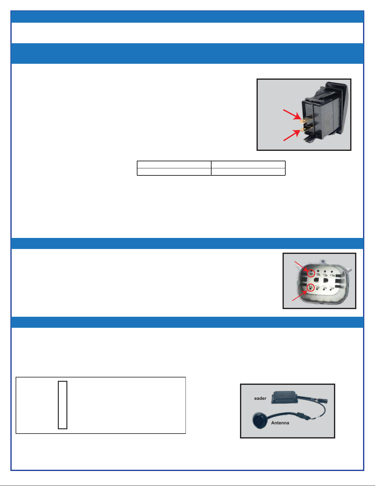
• Also check the solenoid output voltage on pin #3 (gray) which should be +12VDC any time
the green LED is ON for 6-seconds.
- If it is not +12V, check the truck wire harness, the ground, and the solenoid connections
and repair where needed.
Pin 1 Pin 3
Possible Cause #5:
The Reader is OK but the Antenna Connector is Unplugged
Actions ToTake:
• Replug the antenna to the reader
- The antenna LED status LEDs should initiate the QC test sequence.
- Verify the antenna “sees” the Wristband Key or Keychain Tag by swiping it.
- If the Key is not detected, then recheck Possible Cause #3 above
Possible Cause #6:
The Terminals on the Reader Harness or Antenna Harness are NOT Making
Proper Connection.
Actions ToTake:
• Check the connector pin outs and verify ground and power is present on the correct terminals.
1
2
3
4
5
Brown - Ground when Red is ON
White - RFID Signal
Violet - RFID Signal
Black - Ground when Green LED is ON
Red - +12VDC
ON
Antenna
Connector
• To check for RFID signal, unplug the antenna and
check for continuity.
- If there is continuity between the White and
Violet wires, the circuit is OK.
}Do NOT Test
With Voltmeter!!!
NST13308-M115-02_A ◄► 2021-06-23 ◄► Page 7
2. What to do if the Door Does NOT Unlock When Pressing the Unlock Switch:
TROUBLESHOOTING - KEYLESS ENTRY
Possible Cause #1: The Unlock Switch is Damaged or Defective
*Note: the Door DOES unlock when swiped with a Key
Actions To Take:
• Try unlocking the door using the Wristband Key or Keychain Key.
- If the door unlocks, then the unlock switch or wire harness is defective.
• Verify that a ground signal is present at the switch on the COM terminal when
the switch is NOT pressed to check the wire harness connection.
- If there is a ground present on the COM terminal, then press the switch and
check for ground on the normally open (NO) terminal.
- If ground is NOT detected on both terminals, then the switch is defective
• Try a QC Test
- Unplug the Antenna/Reader from the wire harness then reconnect it.
- Observe the following:
- The location code flashes twice:
- Data Bus Test - If the Data Bus is present, the Red LED flicker flashes for 10-seconds (if the antenna is at
the Master Node, the flicker flash is a short burst).
-Input Check - Both LEDs turn ON solid for 15-seconds.
- - Unlock Switch Test
- Press the unlock switch
- If the unlock switch input is detected, the Green LED turns OFF and back ON.
- If this does not happen, either the unlock switch or the wire harness is defective.
COM
Terminal
NO
Terminal
1 Flash = Curbside Door 3 Flashes = Bulkhead Door
2 Flashes = Driver Door 4 Flashes = Rear Door
Possible Cause #3:
The Connector Terminal Crimps Have Failed
Actions To Take:
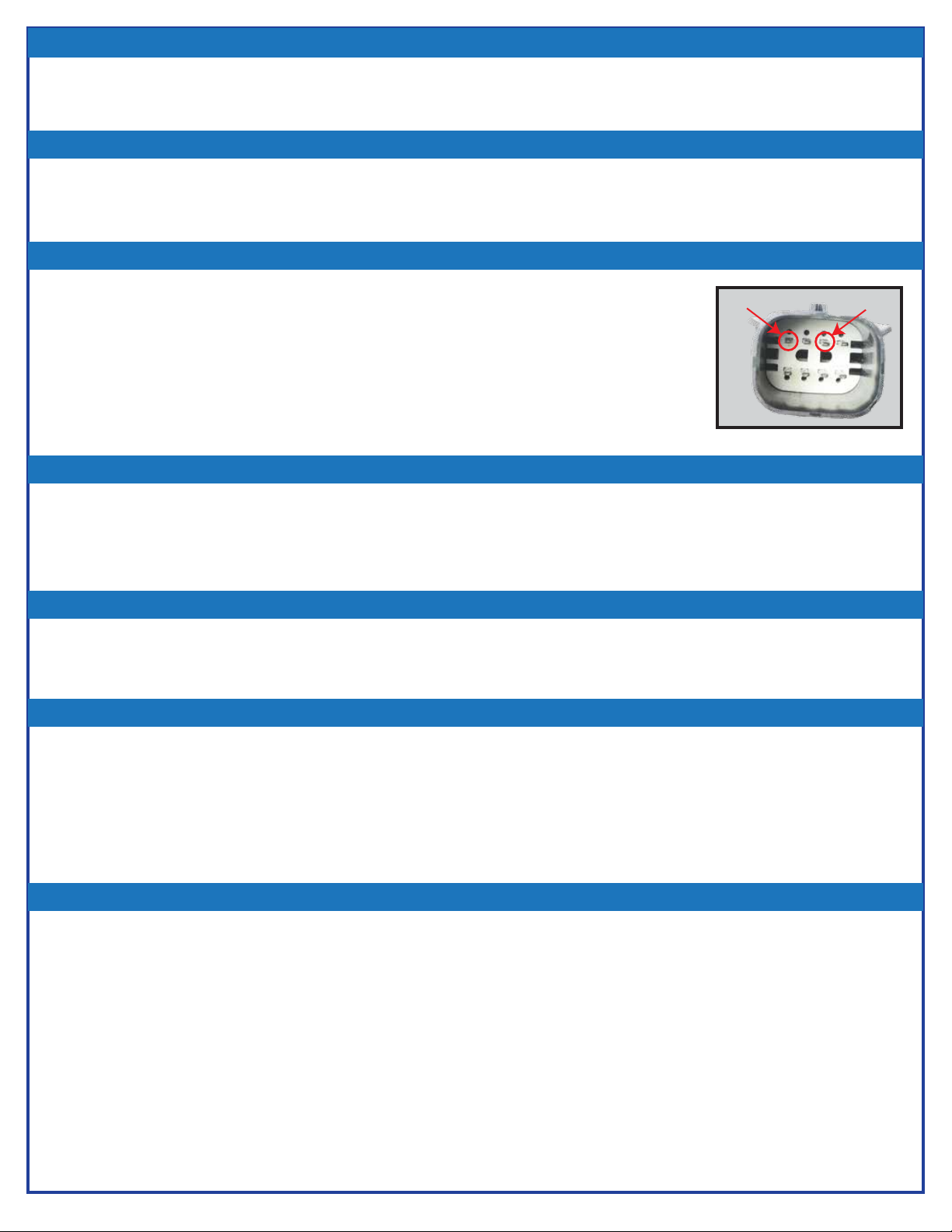
• Using a ground input, touch pin #5 (Gray/Yellow) on the reader connector.
- If the Red LED flashes once and the door unlocks, then the antenna and antenna connector are OK.
• Locate the connector or crimp problem and repair or replace the wire harness.
• If the Red LED does NOT flash and you have verified that there is a ground input on pin #5 (Gray/Yellow) when
the switch is pressed, then replace the antenna.
Possible Cause #2:
The Harness Connection Between the Switch and the Antenna/Reader Has Failed
Actions To Take:
• If the switch is OK, check the input pin, pin #5 (Gray/Yellow), on the reader connector
on the truck harness.
- A ground should be on this terminal when the switch is pressed.
- If there is no ground, repair or replace the harness.
• If the switch is OK, repeat the QC and Unock Switch tests in Possible Cause #1.
• Check the wire harness and connectors and repair as needed.
.
Pin 1
Pin 5
1
2
3
4
5
Brown - Ground when Red is ON
White - RFID Signal
Violet - RFID Signal
Black - Ground when Green LED is ON
Red - +12VDC
ON
Antenna
Connector
• To check for RFID signal, unplug the antenna and
check for continuity.
- If there is continuity between the White and
Violet wires, the circuit is OK.
}Do NOT Test
With Voltmeter!!!
Antenna
Reader

NST13308-M115-02_A ◄► 2021-06-23 ◄► Page 8
TROUBLESHOOTING - KEYLESS ENTRY
Possible Cause #4:
Antenna Has Failed
Actions To Take:
• If the unlock switch is OK and there is +12V on the input pin #3 (Gray wire) when
the switch is pressed, unplug the antenna from the wire harness and then
reconnect it.
• Observe the QC Test
- The location code flashes twice:
- Data Bus Test - If the Data Bus is present, the Red LED flicker flashes for 10-seconds (if the antenna is at the
curbside door, the flicker flash is a short burst).
-Input Check - Both LEDs turn ON solid for 15-seconds.
• Unlock Switch Test
- Press the unlock switch
* If the unlock switch input is detected, the Green LED turns OFF and back ON.
* If this does not happen, either the unlock switch or the wire harness is defective.
* If you have determined that input is present on pin #3, then replace the antenna.
• Present the Wristband Key or Keychain Key to the antenna.
- If both LEDs don’t turn OFF when the key is present or when it is removed, then the antenna has failed.
- Replace the antenna.
1 Flash = Curbside Door 3 Flashes = Bulkhead Door
2 Flashes = Driver Door 4 Flashes = Rear Door
Pin 1 Pin 3
NST13308-M115-02_A ◄► 2021-06-23 ◄► Page 9
TROUBLESHOOTING - KEYLESS ENTRY
3. What to do if the door does NOT unlock when swiped or unlock switch is
pressed, but the green LED turns ON for 6-seconds:
Possible Cause #2: No Power to the Solenoid
Possible Cause #1: Solenoid does not have a good ground connection
Actions To Take:
• Check that the ground wire to the solenoid is making good contact with the truck chassis by using a voltmeter. If
there is no ground, correct the ground connection.
Actions To Take:
• Verify +12VDC on pin #1 (Red) using a volmeter.
• Verify +12VDC on pin #3 (Gray) of the reader connector when the Green LED is ON.
- If there is NO +12VDC, check the connector to make sure a crimp or pin is not
damaged. If the harness and crimps are OK, replace the reader.
• If there is +12VDC on the reader connector when the LED is Green, check for
+12VDC on the solenoid. If there is NO +12VDC at the solenoid, repair the wire
harness.
Actions To Take:
• If there is power and ground at the correct pins to the solenoid, check the solenoid itself. If the solenoind rod does
not move when the solenoid or door locking mechanism is energized, either the solenoid is jammed or defective.
Repair or replace the solenoid.
Possible Cause #3: Solenoid Rod is Jammed
Actions To Take:
• Check the door’s alignment if the reader and solenoid appear to be working correctly.
• Adjust the door as required to make it operate properly.
Possible Cause #4: Door is Jammed
Actions To Take:
• The internal circuit breaker in the reader module will detect a short in the wire harness, connector or solenoid. Locate the short
and repair it.
• Reset the system by swiping the antenna or pressing the unlock switch.
Note: “Smart switches’ with internal circuit breakers protect the outputs. When the short is corrected, the smart switch must be
reset. To reset the reader, swipe it using a Wristband Key or Keychain Key or unplug the unit to reset the circuit. There is NO
visual indication that the internal circuit protection has been tripped.
Possible Cause #5: Short in the Wire Harness or Solenoid
Actions To Take:
• If you have verified there is NO short in the wire harness, connection, or solenoid, AND YOU HAVE RESET POWER TO THE
READER, then the reader is defective.
• Replace the reader.
Possible Cause #6: Internal Short in the Reader
Pin 1 Pin 3

NST13308-M115-02_A ◄► 2021-06-23 ◄► Page 10
TROUBLESHOOTING - KEYLESS ENTRY
4. What to do if the unlock response is slow when swiped with the Wristband
Key:
Possible Cause #1: Data Bus Failure Due to Wire Harness or Connector Problem
Actions To Take:
• Swipe each antenna and observe the Red LED.
-If that reader is NOT connected to the data bus, then the RED LED will continue to flash during the 6-second
solenoid timer.
• Verify the problem by unpluging the reader then repluging it, then observe the Mod QC test:
- The location code flashes twice:
- The data bus operation is tested and if the data bus is present, the Red LED flicker flashes for 10-seconds
(if the reader is at the curbside door, the flicker flash is a short burst).
- If there is NO flicker flash, the data bus is not active.
• A failure in the ID location pins in one of the readers will cause a “location conflict” on the data bus. For example,
the ground input on pin #7 has failed (no ground). The system “thinks” there are two Master Nodes present
which control the data bus traffic.
• Unplug each antenna and observe the QC test.The first test identifies the reader location. If it indicates two units
with same location ID, then you have found the problem. Fix the connector or wire harness.
Possible Cause #2: Internal Short in the Reader
Actions To Take:
• Verify there are no wire harness or connector problems.
• Verify all of the antenna-locations are correctly identified.
• Unplug the antenna reader from the wire harness and reconnect it.
• Observe the Mod QC Test:
1) The location code flashes twice
2) The data bus operation is tested and if the data bus is present, the Red LED flicker flashes 10-seconds (Note: If the reader
is at the Master Node, the flicker flash is a short burst). If the Red LED does NOT flicker flash, then the data bus cicuit
has failed.
• Replace the reader.
1 Flash = Curbside Door 3 Flashes = Bulkhead Door
2 Flashes = Driver Door 4 Flashes = Rear Door

NST13308-M115-02_A ◄► 2021-06-23 ◄► Page 11
1. What to do if the Status LEDs Flash Data Bus Failure:
Possible Cause #1: Short in the Wire Harness
Actions To Take:
• If the harness is not shorted to power, disconnect the wire harness connector for power and ground located under
the hood.
• Check different points in the wire harness and see if the chassis ground is present. With the wire harness
disconnected from the truck, NO ground should be detected.
• If a ground is detected, locate the problem and repair it.
• If the harness is not shorted to power or chassis ground, then it can be shorted to the ground or power wire in the
harness. With the harness disconnected from the battery, check for +12VDC and ground between the power
and ground wires in the harness. If +12VDC or ground is connected to the data wire (tan), then locate the
problem and repair it.
Possible Cause #1: Two Readers with the Same Location Key
Actions To Take:
• Run a QC test on each of the readers to determine which two readers have the same location key
and repair the location point in the wire harness.
• If the failure is not in the wire harness then it is in the reader so replace the reader.
2. What to do if the Unlock or Start Response is Slow When Swiped:
Actions To Take:
• For a short or open in any of the wires (Tan-Data, Red-Power, Ground-White or Black), see Possible Cause #1
above.
Possible Cause #2: A Short or Open in the Wire Harness
TROUBLESHOOTING - DATA BUS

NST13308-M115-02_A ◄► 2021-06-23 ◄► Page 12
BLOCK DIAGRAM
THERE ARE 4 DIFFERENT CONFIGURATIONS AVAILABLE FOR THE M115 SYSTEM.
SINGLE NODE - DOUBLE NODE - TRIPLE NODE - QUAD NODE
THE (X) IN THE M115-RX LABEL IS DESIGNATED BY THE NUMBER OF NODE'S IN THE SYSTEM.
EXAMPLE - A TRIPLE NODE SYSTEM WOULD HAVE M115-R3 LABELED ON EACH NODE, WHILE A
QUAD NODE SYSTEM WOULD HAVE M115-R4 LABELED ON EACH NODE.
THE NODE'S ARE THEN IDENTIFIED BY THE GROUND CONNECTIONS OF THE LOCATION PIN'S 7 &
8. SEE TABLE BELOW FOR IDENTIFYING EACH NODE.

NST13308-M115-02_A ◄► 2021-06-23 ◄► Page 13
PARTS
Minimum Order - $25
Call Factory For Pricing and Availability
(Indiana Local: 1-574-294-2570; Toll Free: 1-800-294-2570; Fax: 1-574-293-1611)
TTI Part Number Part Description Part Picture
M115-A Antenna, 2.5" diameter
M115-R1 Reader - Installed 1 per truck
ID code special / single unit
M115-R2 Reader - Installed 2 per truck
ID code special / single unit
M115-R3 Reader - Installed 3 per truck
ID code special / single unit
M115-R4 Reader - Installed 4 per truck
ID code special / single unit
M120 Wristband Key
M125 Keychain Key
HNS13235-3 Antenna Extension Cable
GSK13199-1 Gasket - Antenna, 2" diameter
HDW13390-1 Nut - Antenna, 2" diameter,
NPSM thread

NST13308-M115-02_A ◄► 2021-06-23 ◄► Page 14
Indiana Local 1-574-294-2570
Toll Free 1-800-294-2570
Fax 1-574-293-1611
Phone 1-800-294-2570
Fax 1-574-293-1611
Email sales@touchtronics.com
TECHNICAL SUPPORT NUMBERS
SALES SUPPORT NUMBERS
TECHNICAL SUPPORT VIA WEBSITE / EMAIL
www.touchtronics.com
Techsupport@touchtronics.com or 'Contact Request' link on
the web page
PARTS
1. Each individual product is warranted under the TouchTronics Limited Warranty program for one (1)
full year from the date of purchase or two (2) years from the date of manufacture.
2. No product will be covered under the TouchTronics Limited Warranty program that has a
maunufacture date older than two (2) years.
3. To receive technical support or warranty service, call our technical support center at 1-800-294-2570
during regular business hours.
4. To enable our technical staff to better serve you, please have the product and vehicle information
available when you call.
TOUCHTRONICS, INC. WARRANTY POLICES AND PROCEDURES
Model Number
Serial Number
Date of Purchase
Date of Installation
Dealer Name
Dealer Phone
Make / Model
VEHICLE INFORMATION
PRODUCT INFORMATION
* Fill in all pertinent information at the time of purchase or installation.
© 2021 TouchTronics, Inc. All Rights Reserved.TouchTronics, the TouchTronics logo, and other TouchTronics marks are owned by TouchTronics and may
be registered. TouchTronics assumes no responsibility for any errors that may appear in this manual. Information contained herein is subject to change
without notice.
FCC Compliance and Advisory Statement - This hardware device complies with Part 15 of the FCC Rules. Operation is subject to the following two
conditions:
1. This device may not cause harmful interference.
2. This device must accept any interference received, including interference that may cause undesired operation.
Any changes or modifications not expressly approved by the party responsible for compliance could void the user’s authority to operate the equipment.
Canadian Compliance Satement - This device contains licence-exempt transmitter(s)/receiver(s) that comply with Innovation, Science and Economic
Development Canada’s licence-exempt RSS(s). Operation is subject to the following two conditions:
1. This device may not cause interference.
2. This device must accept any interference, including interference that may cause undesired operation of the device.
*********************************************************************************************************************************************
© 2021 TouchTronics, Inc. Tous droits réservés.TouchTronics, le logo TouchTronics et les autres marques TouchTronics sont la propriété exclusive de
TouchTronics et sont susceptibles dêtre des marques déposées. Toutes les autres marques sont la propriété exclusive de leurs détenteurs respectifs.
TouchTronics décline toute responsabilité en cas derreurs dans ce manuel. Les informations énoncées dans le présent document peuvent faire lobjet de
modifications sans avis préalable.
Déclaration FCC - Cet équipement a été testé et déclaré conforme à la section 15 du règlement de la FCC. Son fonctionnement est soumis aux
conditions suivantes:
1. Léquipement concerné ne doit pas causer dinterférences dangereuses.
2. Il doit accepter toute interférence reçue, y compris les interférences risquant dengendrer unfonctionnement indésirable
Toutes modifications ou tous changements effectués sans laccord exprès de la partie responsable de la conformité aux normes pourraient contraindre
lutilisateur à ne plus utiliser son équipement.
Déclaration du Ministère des Communications Canadien - L’émetteur/récepteur exempt de licence contenu dans le présent appareil est conforme aux CNR
d’Innovation, Sciences et Développement économique Canada applicables aux appareils radio exempts de licence. L’exploitation est autorisée aux deux
conditions suivantes:
1. L’appareil ne doit pas produire de brouillage.
2. L’appareil doit accepter tout brouillage radioélectrique subi, même si le brouillage est susceptible d’en compromettre le fonctionnement.
FCC & ISED COMPLIANCE

NST13308-M115-02_A ◄► 2021-06-23 ◄► Page 15
NOTES

NST13308-M115-02_A ◄► 2021-06-23 ◄► Page 16
NOTES
Table of contents
Other TouchTronics Remote Control manuals


Popular Remote Control manuals by other brands


/BG(C)E manual")


Daikin
Daikin BRC7GA56 Operation manual

Sandstrom
Sandstrom SANDPRES quick start guide

Meltem
Meltem M-WRG-FBH user guide

GUIYUAN INDUSTRY DEVELOPMENT
GUIYUAN INDUSTRY DEVELOPMENT S1XT-DC06 quick start guide

INVENTOR
INVENTOR V2MCI-24 owner's manual

La Crosse Technology
La Crosse Technology TX3U instruction manual