TOUGH-WORKS DP8 User manual

8-INCH DRILL PRESS
INSTRUCTION
MANUAL
IMPORTANT:
For your own safety, read and follow all of the Safety
Guidelines and Operating Instructions before operating
this product.
DP8

2
TABLE OF CONTENTS
SPECIFICATIONS
TABLE OF CONTENTS
TABLE OF CONTENTS ...............................................................................................
2
SAFETY GUIDELINES ................................................................................................
8
PACKAGE CONTENTS ..............................................................................................
10
KEY PARTS DIAGRAN
..................................................................................................
11
ASSEMBLY INSTRUCTIONS........................................................................................
12
OPERATION .................................................................................................................
13
MAINTENANCE ............................................................................................................
15
TROUBLESHOOTING GUIDE .....................................................................................
16
EXPLONED VIEW .........................................................................................................
18
PARTS LIST ..................................................................................................................
19
WARRANTY ..................................................................................................................
20
ELECTRICAL SAFETY .................................................................................................
9
SPECIFICATIONS ......................................................................................................
2
DP8
Motor 120V, 60Hz
Speed 620~3100RPM
Chuck size 1/2 in.
Taper JT33
Spindle travel 2 in.
Swing 8 in.
Drilling capacity 1/2 in.
DP8
Model
250WPower
Net weight 33 lb.

BD4603
SAFETY GUIDELINES
SAFETY GUIDELINES - DEFINITIONS
3
WARNING ICONS
Your power tool and its Instruction Manual may contain “WARNING ICONS”(a
picture)symbol intended to alert you to and/or instruct you how to avoid a potentially
hazardous condition). Understanding and heeding these symbols will help you operate
your tool
better and safer. Shown below are some of the symbols you may see.
SAFETY ALERT: Precautions that involve your safety.
DANGER: Indicates an imminently hazardous situation which, if not
avoided, will result in death or serious injury.
WARNING: Indicates a potentially hazardous situation which, if not
avoided, could result in death or serious injury.
CAUTION: Indicates a potentially hazardous situation which, if not
avoided,may result in minor or moderate injury.
NOTICE: Used without the safety alert symbol indicates potentially
hazardous situation which, if not avoided, may result in property damage.
WARNING
!
DANGER
!
CAUTION
!
NOTICE
PROHIBITION
WEAR EYE PROTECTION: Always wear safety goggles or safety glasses with
side shields.
WEAR RESPIRATORY AND HEARING PROTECTION: Always wear respiratory
and hearing protection.
READ AND UNDERSTAND INSTRUCTION MANUAL: To reduce the risk of injury,
user and all bystanders must read and understand instruction manual before using
this product.
KEEP HANDS AWAY FROM THE MOVING PART AND CUTTING SURFACE:
Failure to keep your hands away from the moving part and cutting surface will
result in serious personal injury.
SUPPORT AND CLAMP WORK
Some dust created by power sanding, sawing, grinding,drilling and other construction
activities contains chemicals known to the state of California to cause cancer, birth
defects or other reproductive harm. Some examples of these chemicals are:
Lead from lead-based paints.
Crystalline silica from bricks and cement and other masonry products.
Arsenic and chromium from chemically-treated lumber.
WARNING
!
Your risk from these exposures varies, depending on how often you do this type of work.
To reduce your exposure to these chemicals: work in a well ventilated area, and work
DP8

SAFETY GUIDELINES
with approved safety equipment, such as those dust masks that are specially designed
sanding, sawing, grinding, drilling, and other construction activities. Wear protective
clothing and wash exposed areas with soap and water. Allowing dust to get into your
mouth, eyes, or lay on the skin may promote absorption of harmful chemicals.
WARNING
!
4
To avoid electrical hazards, fire hazards or damage to the tool, use proper circuit protection.
This tool is wired at the factory for 110-120 Volt operation. It must be connected to a 110-120
Volt /15 Ampere time delay fuse or circuit breaker. To avoid shock or fire, replace power cord
immediately if it is worn, cut or damaged in any way.
Before using your tool, it is critical that you read and understand these safety rules. Failure to
follow these rules could result in serious injury to you or damage to the tool.
DP8

GENERAL SAFETY INSTRUCTIONS
BEFORE USING THIS POWER TOOL
Safety is a combination of common sense,
staying alert and knowing how to use your
power tool.
To avoid mistakes that could cause serious
injury, do not plug the tool in until you have
read and understood the following.
Read all instructions before operating
product.Failure to follow all instructions listed
below may result in electric shock, fire and
/or serious injury.
1. READ and become familiar with the
entire Instruction Manual. LEARN
the tool’s application, limitations and
and possible hazards.
2. KEEP GUARDS IN PLACEand in working
order.
3. KEEPWORK AREACLEAN. Cluttered
areas and benches invite accidents.
4. DO NOT USE IN DANGEROUS
ENVIRONMENTS. Do not use power tools
in damp locations, or expose them to rain
or snow. Keep work area well lit.
5. KEEP CHILDREN AWAY. All visitors and
bystanders should be kept a safe distance
from work area.
6. DO NOT FORCE THE TOOL. It will do the
job better and safer at the rate for which it
was designed.
7. WEAR PROPER APPAREL.Do not wear
loose clothing, gloves, neckties, rings,
bracelets or other jewelry which may get
caught in moving parts. Nonslip footwear
is recommended. Wear protective hair
covering to contain long hair.
8. ALWAYS WEAR EYE
PROTECTION. Any power tool can
throw foreign objects into the eyes
ALWAYS wear Safety Goggles (not
glasses) that comply with ANSI Safety
standard Z87.1. Everyday eyeglasses
have only impact–resistant lenses. They
ARE NOT safety glasses. NOTE:Glasses
or goggles not in compliance with ANSI
Z87.1 could seriously injure you when
they break.
9. WEAR A FACE MASK OR
DUST MASK.Sanding operation
produces dust.
10. DISCONNECT TOOLS FROM POWER
SOURCE before servicing, and when
changing accessories such as blades,
bits and cutters.
WARNING
!
BD4603
5
12. USE RECOMMENDED ACCESSORIES.
Consult this Instruction Manual for
recommended accessories. The use of
improper accessories may cause risk of
injury to yourself or others.
13. NEVER STAND ON THE TOOL. Serious
injury could occur if the tool is tipped
or if the cutting tool is unintentionally
contacted.
14. MAINTAIN TOOLS WITH CARE. Keep
tools sharp and clean for best and safest
performance. Follow instructions for
lubricating and changing accessories.
DP8
and could cause permanent eye damage.
11.USE PROPER EXTENSION CORDS.
Make sure your extension cord is in
good condition.When using an extension
cord, be sure to use one heavy enough
to carry the current your product will draw.
An undersized cord will result in a drop
in line voltage and in loss of power
which will cause the tool to overheat.
The table on page 8 shows the correct
size to use depending on cord length
and nameplate ampere rating. If in
doubt, use the next heavier gauge.
The smaller the gauge number, the
heavier the cord.
15.CHECK FOR DAMAGED PARTS.
Before further use of the tool, a guard or
other part that is damaged should be
SAFETY GUIDELINES

DRILL PRESS SAFETY
6
18.
Dust generated from certain materials
can be hazardous to your health. Always
operate saw in well-ventilated area and
provide for proper dust removal.
19.
People with electronic devices, such
as pacemakers, should consult their
physician(s) before using this product.
close proximity to a heart pacemaker
could cause interference or failure of the
pacemaker.
20. WEAR HEARING PROTECTION
to reduce the risk of induced
hearing loss.
WARNING
!
DANGER
!
carefully checked to determine that it
will operate properly and perform its
intended function– check for alignment
of moving parts, binding of moving parts,
breakageof parts, mounting and any other
conditions that may affect its operation.
A guard or other part that is damaged
should be properly repaired or replaced.
16. NEVER LEAVE THE TOOL RUNNING
UNATTENDED. TURN THE POWER “OFF”.
Do not walk away from a running tool until
the blade comes to a complete stop and the
tool is unplugged from the power source.
17. DO NOT OVERREACH. Keep proper footing
and balance at all times.
For your own safety, do not try to use your
drill press or plug it in until it is completely
assembled and installed according to the
instructions, and until you have read and
understood this instruction manual:
WARNING
!
to move during certain operations, bolt the
workbench to the floor.
2. THIS DRILL PRESS is intended for use in
dry conditions, indoor use only.
3. WEAR EYE PROTECTION. USE a face or
dust mask along with safety goggles if
drilling operation is dusty.
USE ear protectors, especially during
extended periods of operation.
4. DO NOT wear gloves, neckties, or loose
clothing.
5. DO NOT try to drill material too small to
be securely held.
6. ALWAYS keep hands out of the path of
a drill bit.
Avoid awkward hand positions where a
sudden slip could cause your hand to move
into the drill bit.
7. DO NOT install or use any drill bit that
exceeds 175 mm (7 in.) in length or extends
150 mm (6 in.) below the chuck jaws.
They can suddenly bend outward or break.
8. DO NOT USE wire wheels, router bits,
shaper cutters, circle (fly) cutters,
or rotary planers on this drill press.
9. WHEN cutting a large piece of material,
make sure it is fully supported at the table
height.
10.DO NOT perform any operation freehand.
ALWAYS hold the workpiece firmly against
the table so it will not rock or twist. Use
clamps or a vise for unstable workpieces.
11.MAKE SURE there are no nails or foreign
objects in the part of the workpiece to
be drilled.
1. YOUR DRILL PRESS MUST BE BOLTED
securely to a workbench. In addition,
if there is any tendency for your drill press
12. CLAMP THE WORKPIECE OR BRACE IT
against the left side of the column to
prevent rotation. If it is too short or the
table is tilted, clamp it solidly to the table
and use the fence provided.
13. IF THE WORKPIECE overhangs the table
such that it will fall or tip if not held, clamp
it to the table or provide auxiliary support.
14. SECURE THE WORK. Use clamps or a vise
to hold the work when practical. It’s safer
SAFETY GUIDELINES
DP8

BD4603
7
than using your hand and it frees both
hands to operate tool.
15. WHEN using a drill press vise, always
fasten to the table.
16. MAKE SURE all clamps and locks are firmly
tightened before drilling.
17. SECURELY LOCK THE HEAD and table
support to the column, and the table to
the table support before operating the
drill press.
18. NEVER turn your drill press on before
clearing the table of all objects (tools,
scraps of wood, etc.)
19. BEFORE STARTING the operation, jog
the motor switch to make sure the drill
bit does not wobble or vibrate.
20. LET THE SPINDLE REACH FULL SPEED
before starting to drill. If your drill press
makes an unfamiliar noise or if it vibrates
excessively, stop immediately, turn the
drill press off and unplug. If do not restart
the unit until the problem is corrected.
21. DO NOT perform layout assembly or set
up work on the table while the drill press
is in operation.
22. USE THE RECOMMENDED SPEED for any
drill press accessory and for different
workpiece material. READ THE INSTRUC
TIONS that come with the accessory.
23. WHEN DRILLING large diameter holes,
clamp the workpiece firmly to the table.
Otherwise, the bit may grap and spin the
workpiece at high speeds.
DO NOT USE fly cutters or multiple-part
hole cutters, as they can come apart or
become unbalanced in use.
24. MAKE SURE the spindle has come to a
complete stop before touching the
workpiece.
25. TO AVOID INJURY from accidental
starting, always turn the switch “OFF”
and unplug the drill press before installing
or removing any accessory or attachment
or making any adjustment.
26. KEEP GUARDS IN PLACE and in working
order.
27. USE ONLY THE SELF-EJECTING TYPE
SAFETY GUIDELINES
CHUCK KEY as provided with the drill
press.
28.
TO AVOID BEING PULLED INTO THE
SPINNING TOOL - Tie back long hair and
roll long sleeves above elbows.
WARNING
!
29. Drum sanders must never be operated
on this drill press at a speed greater
than the speed rating of the drum sander.
30.
Feed workpiece into a sanding drum or
other approved accessory, against the
direction of rotation.
31.
A kickback occurs when workpiece
suddenly binds on the cutting edge of
the tool and the workpiece is thrown by
the cutter in the direction of the cutter’s
rotation. This can cause serious injury.
32.
Do not allow familiarity (gained from
frequent use of your drill press) to become
commonplace. Always remember that
a careless fraction of a second is sufficient
to inflict severe injury.
WARNING
!
WARNING
!
WARNING
!
DP8

8
DANGER
DP8
LASER SAFETY
This tool is equipped with a patented precision
cross-pattern laser alignment and centering
guide.
1. Do not stare directly at the laser beam.
Eye damage may occur if you deliberately stare
into the beam.
2. The laser light beam
used in this system is Class II with maximum 1
mW and 660 nm wavelengths.
AVOID DIRECT
EYE EXPOSURE.
3. The laser must be used and maintained in
accordance with the manufacturer ’s instructi-
ons:
• Never aim the beam at any person or an object
other than the workpiece.
• Do not project the laser beam into the eyes of
others.
• Always ensure the laser beam is aimed at a
workpiece without reflective surfaces as the
laser beam could be reflected into your eyes or
the eyes of others.
!
SAFETY GUIDELINES

DO NOT MODIFY THE PLUG PROVIDED.
IMPROPER CONNECTION
grounding conductor can result in risk of
electric shock. The conductor with the green
insulation (with or without yellow stripes) is
or replacement of the electrical cord or plug
grounding conductor to a live terminal.
Total Extension Cord Length
25 8 50 15 100 30 125 40
3-10
10.1 - 12
12.1 - 16
BD4603
9
CHECK
with a qualied electrician or service
personnel if you do not completely understand
the grounding instructions, or if you are not sure
the tool is properly grounded.
GROUNDING INSTRUCTIONS
IN THE EVENT OF A MALFUNCTION OR
BREAKDOWN,
grounding provides a path of
least resistance for electric current and reduces
the risk of shock. This tool is equipped with an
electric cord that has an equipment grounding
conductor and grounding plug. The plug
MUST
be plugged into a matching receptacle that is
properly installed and grounded in accordance
with ALL local codes and ordinances.
WARNING
!
!
ELECTRICAL SAFETY
DP8
GROUNDING INSTRUCTIONS
In the event of an electrical malfunction or short
circuit, grounding reduces the risk of electric
shock.The motor of this machine is wired for 120 V
single phase operation and is equipped with a
3-conductor cord and a 3-prong grounding plug
to fit a grounded type receptacle B. Do not rem-
ove the 3rd prong (grounding pin) to make it fit
into an old 2-hole wall socket or extension cord.
If an adaptor plug is used C, it must be attached
to the metal screw of the receptacle.
Fig. A
Note :The use of an adaptor plug is illegal in some
areas,includingCanada.Check your local codes.
If you have any doubts or if the supplied plug
does not correspond to your electrical outlet,
consult a qualified electrician before proceeding.
EXTENSION CORDS
If you find it necessary to use an extension cord
with your machine, use only 3-wire extension
cords that have 3-prong grounding plug and a
matching 3-pole receptacle that accepts the
tool’s plug. Repair or replace a damaged ext-
ension cord or plug immediately. Make sure
the cord rating is suitable for the amperage
listed on the motorI.D. plate. An undersized
cord will cause a drop in line voltage resulting
in loss of power and overheating.The accom-
panying chart shows the correct size extension
cord to be used based on cord length and motor
I.D. plate amp rating.
Feet Meters
Amp
Rating
(amp)
Feet Meters Feet Meters Feet Meters
18 ga. 16 ga. 14 ga. 14 ga.
16 ga. 16 ga. 14 ga. 14 ga.
14 ga. 12 ga. Not Recommended
Use only UL or CSA approved extension cords
Do not allow familiarity with your tool to make
your careless. Remember that a careless fra-
ction of a second is sufficient to inflict severe
injury.
IMPORTANT
!
The warnings, cautions and instructions det-
ailed in this manual cannot cover all possible
conditions and situations that occur. It must
be understood by the operator that common
sense and caution are factors that cannot be
built into this product, but must be supplied
by the operator.
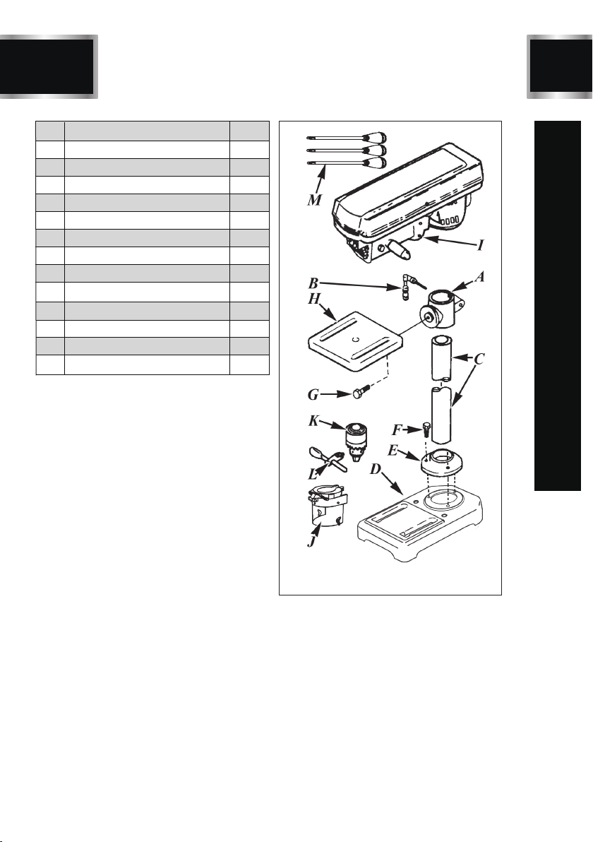
PACKAGE CONTENTS
10
No. Description Qty.
1
1
1
1
1
3
1
1
1
1
1
1
3
A Table support bracket
B Support lock handle
C Column
D Base
E Column support collar
F M8 x 20 hex head screw
G Table bevel lock screw
H Table
I Head assembly
J Chuck guard
K 1/2" Chuck
L Chuck key
M Feed handles
DP8
Fig. B

BD4603
11
KEY PARTS DIAGRAN
DP8
A Table support bracket
B Support lock handle
C Column
D Base
E Column support collar
G Table bevel lock screw
H Table
J Chuck safety guard
K 1/2” chuck
M Feed handle
N On /Off switch
O Switch lock-out key
P Quill return spring
Q Depth stop rod & nuts
R Motor pivot
S Laser switch
T Motor
U Belt & pulley cover
V Depth scale and indicator
W Head lock set-screws
X Cover handle
Y Belt tension lock

ASSEMBLY INSTRUCTIONS
12
BD4603
WARNING
!
For your own safety, never connect plug to
power source outlet until all assembly steps are
complete and you have read and understood
the safety and operating instructions.
The drill press is a heavy power tool and should
be lifted with the help of two PEOPLE OR MORE
to safely assemble it.
DP8
1. Install 3 pcs. M8 x 20 bolts (F,fig 2),threading
them into the base (D, fig 2 & 3) through the
column support collar (E, fig 2 & 3) and tighten
them with a wrench.
2. Slide the table support bracket (A, fig 2 & 3)
onto the column.
3. Install the support lock handle (B, fig 2 & 3)
from the left side into the table support, align the
table with the base and and tighten the support
lock handle by hand.
4. Lift the head assembly (I, fig.1) above and slide
it onto the top of the column.
Note :
The head assembly is heavy and you may
require assistance from a second person.
5. Align the head assembly with the table and
base.
6. Using a 4mm hex (Allen) key, fasten the head
assembly in place by tightening the head lock
set screws (W, fig3) in the right side of the head
casting.
7. Screw the three feed handles (M, fig 2 & 3)
into the the threaded holes in the hub. Instead
of using the knobs for leverage and possibly
stripping them,use a wrench on the flats at the
threaded ends of the handles to tighten.
8. Clean out the tapered hole in the chuck (K,
fig 2 & 3), removing any grease, anti-rust coating
or dirt you find.
9. Clean grease, coating and dirt from the tap-
eredspindle tip with a clean cloth.
10. Open the chuck's jaws as far as they will
go so they are fully retracted into the chuck.
11. Push the chuck up on the spindle as far as
possible.Lightly tap the lower end of the chuck
with a piece of wood to ensure the chuck fits
tightly on the spindle.
12. Install an M5 x 12 pan head screw from the
inside of the pulley cover through the hole and
attach the knob (X, fig 3) to the outside.
1. Locate the laser switch (S, fig 3) on the left
side of the head assembly.
2. Press the tab located below the laser switch
(fig .C) and raise the cover.
3. Insert 2 "AA" batteries, oriented in the dire-
ctions indicated.
4. Close the switch cover.
LASER BATTERIES
Fig. C
Remove the laser light batteries when the tool
is to be stored without use for a few days or
more. If left in position, the batteries might leak
and damage the laser light assembly. Damage
due to leaking batteries is not covered under the
warranty.
CAUTION
!

BD4603
13 DP8
OPERATION
Before using this machine, the operator should
carefully read over this operation manual and
acquaint himself with the construction, controls
and drive system of the drill press.
WARNING
!
Set The Speed
rpm: 620 tr/min
spindle
broche
motor
moteur
rpm: 1100 tr/min
spindle
broche
motor
moteur
rpm: 1720 tr/min
spindle
broche
motor
moteur
rpm: 2340 tr/min
spindle
broche
motor
moteur
rpm: 3100 tr/min
spindle
broche
motor
moteur
DP2001 belt spindle label
1. Open the belt & pulley cover (U, fig 2 & 3) and
choose the best speed for the drilling operation
planned and install the belt in the correct posit-
ion on the pulleys to produce that speed.
2. To move the belt, loosen the belt tension lock
knob (Y, fig 3) on the right side of the head ass-
embly, and let the motor pivot forward so that it
reduces the distance between the drive (motor)
pulley and the spindle pulley.
3. Place the belt on the two pulleys according to
the needed spindle speed.
4. Re-tension the belt when it is set in position by
pivoting the motor away from the spindle (front)
end of the drill press head and re-tighten the belt
tension lock knob.
5. Close the cover.
Be sure the drill press is turned off and unplugged
when the belt & pulley cover is open and you have
your hands in that area.
WARNING
!
Drill Bit
6. Insert the drill bit into the chuck (K, fig 3) far
enough to obtain maximum grip from the chuck
jaws. Make sure the drill bit is centered in the
chuck.
7. Insert the chuck key (L,fig 2) and turn it cloc-
kwise to tighten (and counter-clockwise to loosen)
the drill bit.Tighten the chuck sufficiently to prevent
the bit slipping in the jaws during drilling.As a
test, turn the drill press on and immediately off to
check if the drill bit wobbles.
Table Adjustment
8. To position the table (H, fig 2) vertically, loosen
the support lock handle (B, fig 2) and raise or
lower the table to the desired position. Re-tighten
the support lock handle.
9. Line up the drill bit with the table center hole
when through-boring to avoid damage to the
table.
10. To tilt the table, loosen the table bevel lock
screw (G, fig 2) under the table, tilt the table to
the desired angle (you can use the bevel scale
on the support as a rough gauge) and re-tighten
the table bevel lock screw.
Note :
It is a good idea to always check that the angle
is correct with a protactor or a combination
square.
Depth Control
11. The drilling depth may be controlled by watc-
hing the indicator and depth scale (V fig 3),on the
left side of the drill press head, or it can be
regulated quite precisely by setting the depth
stop nuts on the depth stop rod (Q, fig 3).
12. Check that the chuck key is not in the chuck
and that the drill bit is not contacting the workpie-
ce. Check that the workpiece is properly anch-
ored on the table. Be sure that all the safety rules
at the front of this manual are followed.
Laser
13. Place a work piece on the table.
14. Turn the laser switch to the on (I) position.
15. Lower the drill bit to meet the work piece. The
two laser lines should cross where the drill meets
the work piece.
16. If the laser needs to be adjusted:
● Using a hex wrench, turn the laser adjustment
hex screws (3) counterclockwise.
● Move the laser light housing until the two lines
intersect where the drill meets the work piece.
DO NOT stare directly at the laser lines.
● Re-tighten the adjustment hex screws .
DriLling
17. Turn the switch on.
18. Use the feed handles to push the drill bit slowly

14
DP8
OPERATION
into the material.Particularly in wood drilling, ease
up on the pressure when nearing the point where
the drill bit is about to emerge on the other side of
the workpiece.
19. After drilling a hole, do not release the feed
handle but restrain it lightly, allowing the spring to
raise spindle sleeve gently to its original position.
20. Turn off the drill press.
21. Switch off the laser.
After switching off, never leave the machine un-
attended until it has come to a complete stop.
WARNING
!
In case of any trouble or abnormal noise arising
during this operation, stop the motor at once,
unplug the machine from the power source and
find out the cause. Do not resume until the problem
has been solved.
WARNING
!

BD4603
15
MAINTENANCE
DP8
For your own safety, turn the switch off
and remove the plug from the power source
outlet before adjusting, maintaining or
lubricating your drill press.
WARNING
!
To avoid electrocution or fire, any repairs to
electrical systems should be done by an
authorized repair center.
WARNING
!
1. If power cord is worn, cut or damaged in
any way, have it replaced immediately.
2. After use, blow out or vacuum sawdust and
metal chips that may have accumulated in and
on the motor, the belt and pulley housing, and
the table.
3. Ball bearings are packed with grease at the
factory. They require no further lubrication.
The ball bearings in the spindle and the V-belt
pulley assembly are greased and permanently
sealed.
4. Periodically pull down and lubricate the
grooves in the spindle and the rack (teeth of
the quill), usually about every three months.
5. Occasionally apply a light coat of paste wax
to the column and table to help keep these
surfaces clean and rust-free.
6. Lubricate the table bracket and locking knobs
if they become difficult to use.
7. Cut off the power supply when not in use.
Note :
SERVICE AND REPAIRS should be made by
qualified repair technicians at an authorized
repair center. Improperly repaired tools could
cause serious shock or injury.
Note :
REPLACEMENT PARTS. When servicing,
use only the manufacturer’s recommended
replacement dentical replacement parts
and accessories.

16
BD4603
To avoid injury from an accidental start, turn the switch OFF and unplug the tool before
moving, or making adjustments.
• Consult your Sears Service Center if for any reason the motor will not run.
PROBLEM PROBLEM CAUSE SUGGESTED CORRECTIVE ACTION
Noisy operation
1. Hand grain in wood or lengths
of cutting utes and/ or angles
not equal.
2. Bent drill bit.
Wood splinters
on underside.
WARNING
!
1. Incorrect belt tension.
2. Dry spindle.
3. Loose spindle pulley.
4. Loose motor pulley.
1. Adjust tension. See section “ASSEMB
LYTENSIONING BELT”
2. Lubricate spindle. See Section
“LUBRICATION”.
3. Check tightenness of retaining nut
on pulley, and tighten if necessary.
4. Tighten set screw in motor pulley.
Drill bit burn.
1. Incorrect speed.
2. Chips not coming out of hole.
3. Dull drill bit.
4. Feeding too slowly.
5. Not lubricated.
1. Change speed. See Section “ BASIC
DRILL PRESS OPERATION SPEEDS
AND BELT REPLACEMENT"
2. Retract drill frequently to clear chips.
3. Resharpen drill bit or replace with new bit.
4. Feed fast enough – allow drill to cut.
5. Lubricate drill. See Section “BASIC DRILL
PRESS OPERATION-FEEDING”
Run out of drill
bit pointdrilled
hole not round.
1. Resharpen drill bit correctly.
2. Replace drill bit.
1. No backup material under
workpiece.
1. Use backup material. See Section
“BASIC DRILL PRESS OPERATION”.
Workpiece torn
loose from hand.
1. Not supported or clamped
properly.
1. Support workpiece or clamp it. See Section
“BASIC DRILL PRESS OPERATION”.
Drill bit binds in
workpiece.
1. Workpiece pinching drill bit,
or excessive feed presure.
2. Improper belt tension.
1. Support workpiece or clamp it. See
Section “BASIC DRILL PRESS OPERATION”.
2. Adjust tension. See Section” ASSEMBLY –
TENSIONING BELT”
TROUBLESHOOTING GUIDE
DP8

BD4603
17
PROBLEM PROBLEM CAUSE SUGGESTED CORRECTIVE ACTION
1. Bent drill bit.
2. Worn bearings.
3. Drill bit not properly
installed in chuck.
4. Chuck not properly installed.
Quill returns
too slow or
too fast.
Excessive drill
bit runout or
wobble.
1. Use a straight drill bit.
2. Replace bearings.
3. Install drill properly. See Section
“BASIC DRILL PRESS OPERATION”
and “ASSEMBLY”.
4. Install chuck properly. See Section
“ASSEMBLY –INSTALLING THE
CHUCK”.
1. Coil spring has improper
tension.
1. Adjust spring tension. See Section
“ ASSEMBLY – ADJUSTMENTS
–QUILL RETURN SPRING”.
Chuck will not
stay attached
to spindle. It
falls off when
trying to install.
1. Dirt, grease, or oil on the
tapered inside surface of
chuck or on the spindle’s
tapered surface.
1. Using a non-alcohol based
cleaner, clean the tapered
surface of the chuck and
spindle to remove all dirt,
grease and oil. See Section
“ASSEMBLY – INSTALLING
THE CHUCK”.
DP8
TROUBLESHOOTING GUIDE

18
EXPLONED VIEW
DP8

BD4603
19
PARTS LIST
DP8
POS. DESCRIPTION QTY.
11
21
33
41
51
61
71
81
93
10 3
11 1
12 1
13 1
14 2
15 1
16 1
17 1
18 2
19 1
20 1
21 1
22 2
23 2
24 2
25 2
26 1
27 2
28 4
29 1
30 1
31 4
32 4
33 1
34 2
35 1
36 2
37 2
38
Base
Column support
Screw, hex hd. M8 x 20
Column tube
Table support
Table clamp
Table
Screw hex hd. M12 x 25
Knob
Feed handle rod
Shaft pinion
Hex nut M8
Socket set screw
Hex socket set screw M8 x 8
Motor stop spring
Motor stop
Laser localizer
Motor
Pulley, motor
Hex socket set screw M8 x 10
Hex screw M8 x 25
Washer 8
Lock nut M8
Head
Bushing, rubber
Washer, foam
Guard
V-belt, K26
Washer 6
Pan head screw M6 x 12
Screw, pan M5 x 10
Hex.soc screw M6 x 6
Knob
Screw, pan hd. M5 x 10
Clamp, cord
Pulley, spindle 1
POS. DESCRIPTION QTY.
39 Retaining ring 22 1
40 Pulley insert 1
41 Bearing, ball 6203 2
42 Spacer 1
43 Retaining ring 17 1
44 Pointer 1
45 Depth stop rod 1
46 Nut, hex M10 4
47 Screw, hex. soc. set M8 x 8 1
48 Cap, spring 1
49 Spring, tension 1
50 Star washer 5 2
51 Spring washer 5 2
52 Screw, pan hd. M5 x 6 2
53 Box, switch w/depth scale 1
54 Screw, pan hd. M5 x 14 2
55 Switch plate 1
56 Screw, pan hd. ST4.2 x 9.5 2
57 Switch 1
58 Gasket, quill 1
59 Bearing, ball 6201 2
60 Tube, quill 1
61 Washer 6 1
62 Eye shield 1
63 Hex nut M6 1
64 Retaining ring 11 1
65 Shaft, spindle 1
66 Chuck 1
67 Key, chuck 1
68 Wrench, hex "L" S3 1
69 Wrench, hex "L" S4 1
70 Cord & plug 1
71 Battery compartment 1
72 Screw, pan M4 x 10 2
73 Battery 2
74 Lid, cell box 1
75 Switch, laser 1
76 Hex nut M5 2

DP8
20
BD4603
ONE-YEAR LIMITED WARRANTY
WARRANTY
Having Problems ?
Give us a chance to help you before returning this product
Email :
After the phone:(844) 866-5687
Table of contents


