TOUGH-WORKS TLGS625 User manual
INSTRUCTION
MANUAL
IMPORTANT:
For your own safety, read and follow all of the Safety
Guidelines and Operating Instructions before operating
this product.
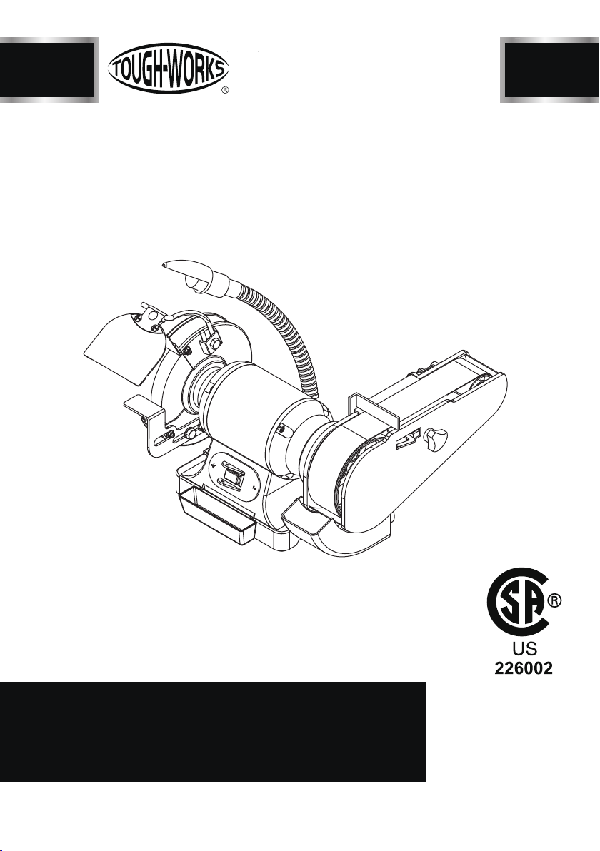
TLGS625
2"X 28" BELT AND 6" WHEEL
BENCH GRINDER SANDER

2
TABLE OF CONTENTS
SPECIFICATIONS
Motor 120V, 60Hz , 2.5A
Speed (no load) 3450RPM
Belt size 2" x 28"
Wheel size
TABLE OF CONTENTS
TABLE OF CONTENTS ...............................................................................................
2
SAFETY GUIDELINES ................................................................................................
4
PACKAGE CONTENTS ..............................................................................................
7
KEY PARTS DIAGRAN
..................................................................................................
8
ASSEMBLY INSTRUCTIONS........................................................................................
10
OPERATION .................................................................................................................
12
MAINTENANCE ............................................................................................................
15
TROUBLESHOOTING GUIDE .....................................................................................
17
EXPLONED VIEW .........................................................................................................
18
PARTS LIST ..................................................................................................................
19
WARRANTY ..................................................................................................................
20
ELECTRICAL SAFETY .................................................................................................
6
SPECIFICATIONS ......................................................................................................
2
6"x3/4"x1/2"
TLGS625

BD4603
SAFETY GUIDELINES
3TLGS625
GENERAL SAFETY GUIDELINES
BEFORE USING THIS POWER
TOOL
• Operate in a safe work environment. Keep
your work area clean, well lit and free of
distractions.
• Keep anyone not wearing the appropriate s
afety equipment away from the work area.
• Store tools properly in a safe and dry location.
Keep tools out of the reach of children.
• Do not install or use in the presence of flam-
mable gases, dust or liquids.
• Always wear impact safety goggles that
provide front and side protection for the eyes.
Wear a full-face shield if your work creates
metal filings or wood chips. (Eye protection
equipment should comply with ANSI Z87.1
standards.)
• Wear gloves that provide protection based on
the work materials or to reduce the effects of
tool vibration.
• Non-skid footwear is recommended to main-
tain footing and balance in the workenvironment.
• Wear the appropriate rated dust mask or
respirator.
• Do not operate any tool when tired or under
the influence of drugs, alcohol or medications.
• Avoid wearing clothes or jewelry that can b-
ecome entangled with the moving parts of a
tool. Keep long hair covered or bound.
• Do not overreachwhen operating the tool.
Proper footing and balance enables better
control in unexpected situations.
• Securely hold the material using both hands.
Applying the material to the grinder with only
one hand can result in a loss of control.
• Never use a tool with a cracked or worn gri-
nding wheel. Change the grinding wheel
before using.
• Replace cracked wheel immediately. Use only
flanges supplied with the grinder.
• Clean dust and debris from beneath the gri-
nding wheels frequently.
• Do not start the tool if the grinding wheel is in
contact with the workpiece.
• Always ensure the safety guards are attached
correctly and do not operate the bench grinder
without the guards attached. Adjust the dista-
nce between the wheel and the tool rest to
maintain a 1/16 in. or less separation as the
diameter of the wheel decreases with use.
• Use an appropriate dust respirator when working
for an extended period of time. This will help
prevent breathing in the fine dust created while
grinding.
• Do not grind on the sides of grinding wheels
unless they are specifically designed for that
purpose.
• Before using the tool on the workpiece, run the
tool at the highest speed, without a load, for at
least 30 seconds in a safe position. Stop im-
mediately if there is any vibration or wobbling
that could indicate poor installation or a poorly
balanced grinding wheel.Check the tool to
determine the cause.
• Do not allow the motor to overload or overheat.
Take breaks to rest the tool.
• Do not subject the grinding wheel to any lateral
pressure as it may damage the tool or cause
it to kickback.
ADDITIONAL SPECIFIC SAFETY
RULES
1. Only use a grinding wheel with the correct arbor
size and shape that matches the grinder’s
spindle.
2. Ensure the grinding wheel has a clean edge.
Check the grinding wheel for wear or chipping
and replace if necessary.
3. Never install more than one grinding wheel at
a time unless the tool and wheels are design-
ed for that purpose.
4. A large amount of sparks will be created when
working with a grinding wheel. Hold the tool
so that sparks fly away from you and other
persons or flammable materials. Have a fully
charged fire extinguisher present.in the event
of a fire.
5. Do not subject the grinding wheel to any
lateral pressure as it may damage the
tool or cause it to kickback.

SAFETY GUIDELINES
4
TLGS625
6. Disconnect tool from power source before
cleaning, servicing, changing parts/accessor-
ies or when not in use.
7. Protect yourself against electric shocks when
working on electrical equipment. Avoid body
contact with grounded surfaces. There is an
increased chance of electrical shock if your
body is grounded.
8. Do not expose tool to rain or water entering a
power tool will increase the risk of electric shock.
9. Do not disconnect the power cord in place of
using the ON/OFF switch on the tool.This will
prevent an accidental startup when the power
cord is plugged into the power supply.
10. Do not alter any parts of the tool or accessories.
All parts and accessories are designed with
built-in safety features that may be compro-
mised if altered.
11. Make certain the power source conforms to
requirements of your equipment.
12. Do not allow the tool to run without load for an
extended period of time, as this will shorten
its life.
13. Do not cover the air vents. Proper cooling of
the motor is necessary to ensure normal life
of normal life of the tool.
14. Avoid unintentional starting. Ensure the switch
is off when connecting to the power source.
15. In the event of a power failure, turn off the
machine as soon as the power is interrupted.
interrupted. The possibility of accidental injury
could occur if the power returns and the unit is
not switched off.
16.Disconnect the power source before installing
or servicing the tool.
17. After making adjustments, make sure that any
adjustment devices are securely tightened.
18. Remove adjusting keys and wrenches before
turning the tool on. A wrench or a key that is left
attached to a rotating part of the tool increases
the risk of personal injury.
19. Never forcethe tool. Excessive pressure could
break the tool, resulting in damage to your
workpiece or serious personal injury.If your tool
runs smoothly under no load, but does not run
smoothly under load, then excessive pressure
is being used.
20. Do not touch an operating motor. Motors can
operate at high temperatures.
21. Only use accessories that are specifically
designed for use with the tool. Ensure the
accessory is tightly installed.
22. Only use an accessory that exceeds the No
Load Speed rating.
23. Do not touch an operating motor. Motors can
operate at high temperatures and can cause
a burn injury.
24. Insert the power cord plug directly to the power
supply whenever possible. Use extension cords
or surge protectors only when the tool's power
cord cannot reach a power supply from the work
area.
25. Do not operate this tool if the power cord is fr-
ayed or damaged as an electric shock may
occur, resulting in personal injury or property
damage.
26. Inspect the tool's power cord for cracks, fraying
or other faults in the insulation or plug before
each use.
27. Discontinue use if a power cord feels more than
comfortably warm while operating the tool.
28. Keep all connections dry and off the ground to
reduce the risk of electric shock. Do not touch
plug with wet hands.
29. Do not allow people, mobile equipment or ve-
hicles to pass over unprotected power cords.
30. This tool vibrates during use. Repeated or long-
term exposure to vibration may cause tempo-
rary or permanent physical injury, particularly
to the hands, arms and shoulders.
ELECTRICAL SAFETY
BD4603
5TLGS625
A separate electrical circuit should be used for your
machines. This circuit should not be less than #12
fuse. If an extension cord is used, use only 3-wire
extension cords which have 3-pronged grounding
type plugs and matching receptacle which will
accept the machine’s plug. Before connecting the
machine to the power line, make sure the switch
is in the "OFF" position and be sure that the ele-
ctric current is of the same characteristics as
indicated on the machine. All line connections
should make good contact.Running
on low voltage
wire and should be protected with a 20-A time-lag
will damage the machine.
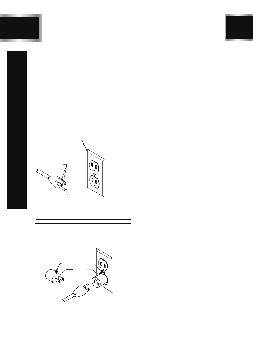
GROUNDED
OUTLET BOX
CURRENT
CARRYING
PRONGS
GROUNDING BLADE
IS LONGEST OF THE 3 BLADES
GROUNDED OUTLET
BOX
GROUNDING
MEANS
ADAPTER
Figure. 1
Figure. 2
MOTOR SPECIFICATIONS
Your machine is wired for 120 V, 60Hz
alternating current. Before connecting the
machine tothe power source, make sure
the switch is in the "OFF" position.
GROUNDING INSTRUCTIONS
!
DANGER!
DO NOT EXPOSETHE MACHINE TO RAIN OR
OPERATE THE MACHINE IN DAMP LOCATIONS.
THIS MACHINE MUST BE GROUNDED
WHILE IN USE TO PROTECT THE OPERATOR
All grounded, cord-connected machines: In the
event of a malfunction or breakdown,grounding
provides a path of least resistance for electric
current to reduce the risk of electric shock. This
machine is equipped with an electric cord having
an equipment grounding conductor and a gro-
unding plug.
FROM ELECTRIC SHOCK.
The plug must be plugged into a matching outlet
that is properly installed and grounded in accor-
dance with all local codes and ordinances.
Do not modify the plug provided–if it will not fit
the outlet, have the proper outlet installed by a
qualified electrician.
Improper connection of the equipment-grounding
conductor can result in risk of electric shock. The
conductor with insulation having an outer surface
that is green with or without yellow stripes is the
equipment-grounding conductor. If repair or repl-
acement of the electric cord or plug is necessary,
do not connect the equipment-grounding condu-
ctor to a live terminal.
Check with a qualified electrician or service per-
sonnel if the grounding instructions are not com-
pletely understood, or if in doubt as to whether the
machine is properly grounded.
Use only 3-wire extension cords that have 3-pronged
grounding type plugs and matching 3-conductor
receptacles that accept the machine’s plug, as shown
in Fig. A.Repair or replace damaged or worn cord
immediately.

6
TLGS625
MINIMUM GAUGE FOR CORD SETS
Use proper extension cords. Make sure your extension
cord is in good condition and is a 3-wire extension
cord which has a 3-pronged grounding type plug
and matching receptacle which will accept the ma-
chine’s plug. When using an extension cord, be
sure to use one heavy enough to carry the current
of the machine. An undersized cord will cause a
drop in line voltage, resulting in loss of power and
overheating. The table shows the correct gauge
to use depending on the cord length. If in doubt,
use the next heavier gauge. The smaller the gauge
number, the heavier the cord.
Ampere rating of
the tool
(120V circuit only)
More
than
Total length of cord
Minimum Gauge for the
extension cord (AWG)
Not more
than
In all cases,make certain the receptacle in que-
stion is properly grounded.
If you are not sure,have a electrician check the
receptacle.
WARNING!
!
ELECTRICAL SAFETY
BD4603
7
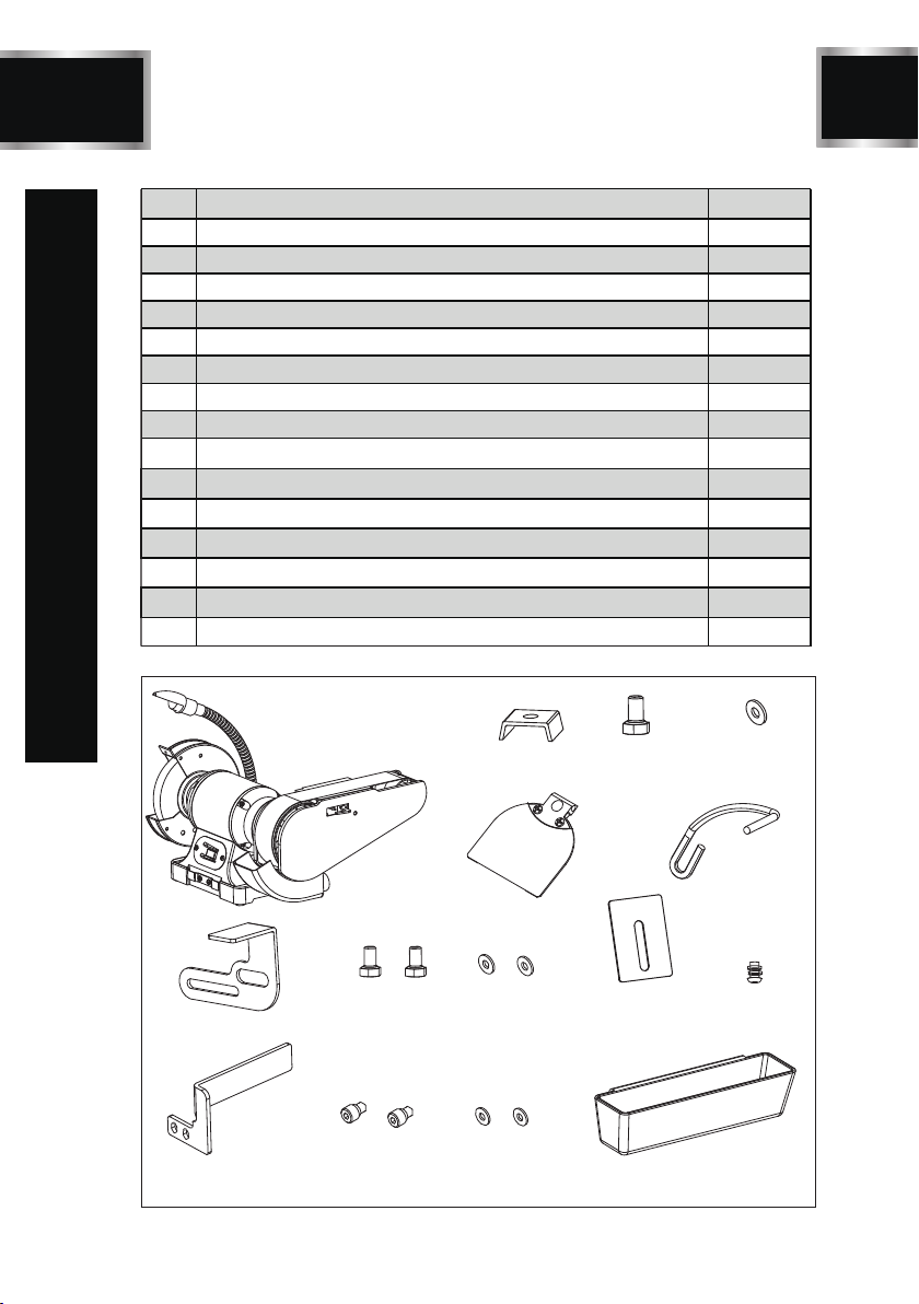
PACKAGE CONTENTS
TLGS625
Description Qty.
Bench grinder sander 1
1
Flat washer D8 1
Hex bolt M8x14 1
Work table deflector
1
Hex column screw M5x12
1
Flat washer D5
2
Coolant tray
Philips screw + flat washer + spring washer M5X10
2
1
1
1
Spark deflector
2
2
1
Pressing block
1
2
3
4
5
6
7
8
9
10
11
12
13
14
15
No.
1234
Eyeshield+Eyeshield pressing plate assy
5
Tool rest
Flat washer D8
Hex bolt M8x10
6
7 8 910 11
12 13 14 15
1
Eyeshield bracket
8
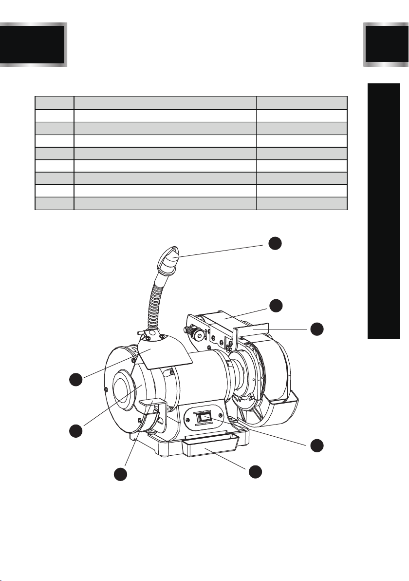
KEY PARTS DIAGRAN
TLGS625
1
2
4
3
5
6
7
8
No. Description Qty.
1LED work light 1
2Sanding belt
Work table deflector
1
3
ON/OFF switch
1
4
Coolant tray
1
5
Tool rest
1
6
Grinding wheel
1
7
Eyeshield assy
1
81

BD4603
9TLGS625
ASSEMBLY INSTRUCTIONS
The tool rest attaches to the inward side of
the guard and provides a surface that must
be used to support the workpiece during
operation.Certain types of grinding/sanding
may require jigs or accessories that will be
used with the tool rests to assure the proper
angle of the workpiece against the wheel.
Failure to install and use the tool rest can lead
to serious personal injury.
To install the tool rests:
1.Loosely attach the tool rests perpendicular
to the belt or wheel surface with the knob
bolts, 5 mm washers and hex nuts.
2.To adjust the angle of the sanding belt
tool rest, use a square or a protractor to
set the angle of the tool rest in relation
to the sanding belt.
3.Adjust both tool rests approximately 1/16
to 1/8 in. from the grinding wheel and the
sanding belt and tighten the knob bolts.
(in Fig.3)shows the correct adjustment
for the tool rest at the grinding wheel.
INSTALLATION TOOL RESTS
Figure 3
The spark guard must be installed and posi-
tioned 1/8 in. from the grinding wheel to minimize
sparks flying towards the operator. The eye
shield must be positioned between the grinding
wheel and the operator's face to protect the
operator from flying debris. This is not a rep-
lacement for safety glasses!
To install the spark guard and eye shield:
1.Using the included 5 mm screw and washer,
install the spark guard as shown(in Fig.4).
SPARK GUARD & EYE SHIELD
2. Attach the eye shield to the support bracket
with the included 6 mm carriage bolt and hex
nut.Use the 8 mm hex bolt and washer to attach
the support bracket to the grinder.
Figure 4
BELT TRACKING
Tracking the sanding belt means to center the
belt on its rollers, so that it runs balanced and
does not make contact with the sides of the
belt cover.
To track the sanding belt:
1. Disconnect the machine from the power
supply.
2. Rotate the grinding wheel.
3. As you rotate the grinding wheel,watch how
the sanding belt rides on the upper roller.If
the belt is tracking properly, the sanding belt
should be centered between the sides of the
belt cover as shown (in Fig. 5).
4. While spinning the wheel, turn the tracking
control knob counterclockwise to make the
belt move to the left, or turn the tracking
control knob clockwise to make the belt move
to the right (in Fig. 6).
5. After the belt is centered, spin the grinding
wheel approximately ten times to ensure
that the belt continues to track properly.
Figure 5
10
TLGS625
ASSEMBLY INSTRUCTIONS
Figure 6
DUST PORT
The dust port is located behind the sanding belt,
below the belt roller.
The operning is 1-1/2in.in diameter and can be
connected to a utility vacuum or a dust collector.
To connect the dust port to a dust collection
system:
1. Place a hose clamp over the dust hose.
2. Slide th hose over the dust port.
3. Secure the hose airtight with the hose clamp.
4. Check the hose with a light tug to ensure it is
secure.

BD4603
11
WARNING
!
OPERATION
TLGS625
The operation of any grinder can result in
foreign objects being thrown into your eyes,
which can result in severe eye damage.
Before beginning power tool operation, always
wear safety goggles or safety glasses with
side shields and a full face shield when needed.
We recommend Wide Vision Safety Mask for
use over eyeglasses or standard safety gl-
asses with side shields.
TEST RUN
Once mounting is complete and adjustments are
done to your satisfaction, you are ready to test
the machine.
To test run the grinder/sander:
1. Plug the machine into the power source.
2. Stand to the side of the grinding wheel and
turn the grinder ON.
The machine should run smoothly with little or
no vibration or rubbing noises. Strange or un-
usual noises should be investigated and corr-
ected before operating the machine further.
If the machine seems okay, stay out of the line
of rotation of the grinding wheel and let it run for
1 to 2 minutes to make sure the wheel is stru-
cturally sound.
All grinding wheels have the potential of b-
reaking apart during operation,causing serious
personal injury or death! Always stand to the
side of the grinder when turning it ON and
wear the proper safety equipment to protect
yourself.
WARNING
!
The grinder is a safe tool when used properly.
In addition to the safety instructions in this man-
ual, the most important safety consideration is to
use common sense at all times. What may be
okay in one situation, may not be safe in another.
Read the following statements to protect yourse-
lf before grinding:
• Make sure all guards and eye shields are in
place.
BEFORE GRINDING
• Remember that grinding often produces sparks.
DO NOT allow anyone to stand in the path of the
sparks. DO NOT grind near flammable liquids or
gases.
• Wear the proper protective clothing. Remember
that particles flying off of a grinding wheel will be
traveling very fast. Wear safety glasses or a face
shield, a dust mask, earplugs, a leather apron and
heavy leather boots.
• DO NOT lean into the workpiece in a manner that
may cause your hands to move into the spinning
wheel if the workpiece slips off.
• Concentrate on the task at hand. STOP grinding/
sanding if there are distractions.
NOTICE! The grinder is designed for use with
hard metals only. Soft metals and wood pro-
ducts should only be used on the sanding belt.
They will quickly load the grinding wheel surface
and ruin its abrasive qualities.
OPERATING GRINDER
To grind with the grinding wheel:
1. Fill the coolant tray 3/4 full with water.
2. Move the red switch to the ON position.
3. Allow the machine to run for at least 1 full minute
to ensure that the grinding wheel is safe for use.
4. Grasp the workpiece tightly and properly support
it on the tool rest.
5. Place the workpiece against the front surface of
the wheel with moderatepressure, moving it back
and forth in a steady, even motion.
6. Regularly dip the workpiece into the coolant tray
to cool it off.
7. When you are ready to stop the grinder, move the
red switch to the OFF position. At this point, DO
NOT continue grinding and DO NOT manually
stop the grinding wheel with your workpiece!
Note: Using too much pressure will slow the motor
and may damage the wheel. Using too little pres-
sure will make the workpiece bounce around and
you will not make good contact with the wheel.
CAUTION! The sanding belt will remove large amo-
unts of material quickly, including your skin. DO NOT
touch the sanding belt and always position your
hands so they will not slip into the belt or get caught
SANDING
12
BD4603 TLGS625
in the belt.
OPERATION
The2in.sanding belt on the machine works great
for non-ferrous metals and wood products. A wide
variety of belts are also available for many types
of materials and stages of finishing.
To sand a workpiece:
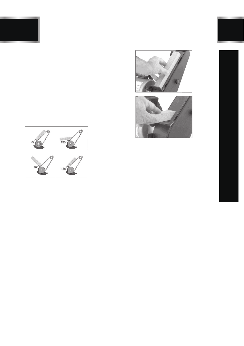
1. Before starting the machine, adjust the angle
of the tool rest so your workpiece is supported
and the area you wish to sand is parallel with
the sanding belt as illustrated(in Fig 7).
2. With the machine plugged into power, stand
to the side of the grinding wheel and move
the red switch to the ON position.
Figure 7
3. Allow the machine to run for at least 1 full mi-
nute to make sure that the grinding wheel is
not going to fly apart and injure you, then move
to the front of the machine.
4. Grasp the workpiece tightly and properly
support it on the tool rest.
5. Press the workpiece evenly against the sa-
nding belt with light pressure (see Fig 8 and 9).
DO NOT press hard. Let the rotation of the
belt do the work.
6. Remove your workpiece regularly to check
the progress the sander has made.
Remember you can always remove more
material but you cannot add it.
7. When you are finished sanding, move the red
switch to the OFF position. DO NOT continue
sanding and DO NOT manually stop the san-
ding belt with your workpiece.
Figure 8
Figure 9

13 TLGS625
MAINTENANCE
1. Maintain the tool with care. A tool in good con-
dition is efficient, easier to control and will have
fewer problems.
2. Inspect the tool components periodically.Repair
or replace damaged or worn components.
3. Follow instructions for lubricating and changing
accessories.
4. When servicing, use only identical replacement
parts. Only use accessories intended for use with
this tool. Replace damaged parts immediately.
5. Maintain the tool’s label and name plate.These
carry important information.
6. Wheels should be dressed periodically to mai-
ntain grinding efficiency,especially if they become
clogged from grinding soft metals. Use a grinding
wheel dresser to restore the wheel’s original
shape.
7. Keep all parts in working order. Check to dete-
rmine that the guard or other parts will operate
properly and perform their intended function.
8. A guard or other part that is damaged should be
properly repaired or replaced. Do not perform
makeshift repairs. Use the parts list provided to
order replacement parts.
9. Disconnect tool when changing grinding wheels.
10. Replace a cracked wheel immediately and use
only flanges supplied with the grinder.
Only qualified service personnel should repair the
tool. An mproperly repaired tool may present a
hazard to the user and/or others.
WARNING
!
Your safety depends, on a large part, on the co-
ndition of the wheel during grinding.A wheel in poor
condition may break apart during rotation,injuring
the operator, a bystander and possibly causing
property damage.
To properly care for your wheel, follow these tips:
• Always transport, store and handle wheels with
care. Wheels may be damaged if they are dro-
pped or if heavy objects are stacked on them.
• Select the right grinding wheel for the job. DO
NOT grind material that is not designed for the
wheel.
• Select the right wheel for the machine. A mac-
hine that rotates at a higher RPM than the wheel
WHEEL CARE
rating may cause the wheel to fly apart.
• Mount the wheels properly (see Replacing
Wheels). Never use a wheel with the wrong
arbor size for the grinder.
• DO NOT abuse the wheel by jamming the work
into the grinding wheel with excessive force.
• Grinding on the side of the wheel may cause
wheel damage.
• Dress the grinding wheel when the surface loses
its abrasive quality or bite.
Dressing restores the grinding wheel’s abrasive
quality. Whenever the front surface of the wheel
loses its abrasive qualities (loading or polishing),
then the wheel should be dressed.
To dress the grinding wheel:
1. With the machine plugged into power, stand
to the side of the grinding wheel and move the
red switch to the ON position.
2. Allow the machine to run for 1 full minute to
make sure that the grinding wheel is not going
to fly apart and injure you, then move to the
front of the machine.
3.Hold the dressing tool firmly on the tool rest
with both hands and press it lightly against
the front surface of the grinding wheel as
shown( in Fig10).
4.Move the dressing tool in a side-to-side motion,
while keeping it even with the front surface of
the grinder.
5.Regularly pull the dressing tool away from the
wheel for visual inspection and repeat Steps 3
&4 until the surface of the wheel appears to be
restored to its normal color and texture.
WHEEL DRESSING
Figure 10
14
TLGS625
MAINTENANCE
Before mounting a new grinding wheel, it must
be inspected. DO NOT assume that a wheel
is in sound condition because it is new. Dam-
age can occur during shipping, with age or
exposure to moisture.
Visually inspect the wheel. Look for any cr-
acks, chips, nicks or dents in the wheel’s
surface. DO NOT use the wheel if you see any
of these, Perform a Ring Test. This
test will
give you an indication of any internal damage
that may not be obvious during
a visual inspection.
To perform a Ring Test:
1. Make sure the wheel that you test is clean
and dry; otherwise, you may get false results.
2. Balance the wheel with your finger in the
hole if size permits, If this is not possible,
hang the wheel in the air with a piece of
cord or string looped through the hole in
the centert.
WHEEL INSPECTION
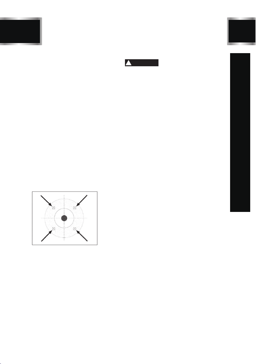
3. At the spots shown in Figure 11, gently
tap the wheel with a light non-metallic
device such asthe handle of a screwdriver
or a wooden mallet.
4. An undamaged wheel will emit a clear me-
tallic ring or "ping" sound in each of these
spots. A damaged wheel will respond with
a dull thud that has no clear tone.
5. DO NOT use it if you determine from the
ring test that the wheel is damaged.
Figure 11
REPLACING WHEELS
The wheel guard assembly must be re-
moved in order to mount or dismount a
grinding wheel.
To remove/mount a wheel:
1. Disconnect the grinder from the power
supply.
2. Remove the three Phillips head screws
and nuts that go through the outer guard.
Take off the outer guard and the rim
guard.
3. Use a wrench on the nut that holds the
wheel on the arbor. Hold the wheel to
prevent it fromturning with your other
hand.The grinding wheel arbor has a
left-handed thread. Loosen the nut by
turning it clockwise.
4. Remove the outer wheel flange and p-
aper disc. Pull the wheel free from the
arbor.There will also be a paper disc
and a wheel flange on the back side of
the wheel which should also be removed.
5. Mount the new wheel in the reverse o-
rder or as shown in Figure 12. Always
make certain there is are paper or fiber
discs between the wheel flanges and
the wheel itself.Tighten the nut snugly
but DO NOT over-tighten.Over-tightening
can crack the wheel.
6. Re-install the guards and shields.
7. Run a new wheel for at least one minute
while standing clear of the line of rota-
tion.If a wheel does have defects it will
generally fail as soon as it gets up to
full speed.
The hazards of using a damaged wheel
include flying chunks of sharp abrasive
material that could cause serious injury
or death. Inspect every grinding wheel
before it is mounted and DO NOT use a
damaged grinding wheel!
WARNING
!
BD4603
15 TLGS625
8. Replacement wheels must have a mi-
nimum rated No Load Speed and a
diameter as listed in the Specifications
section.
Many belts are available with different grit
sizes.
To remove/replace a sanding belt:
1. Disconnect the machine from the power
supply.
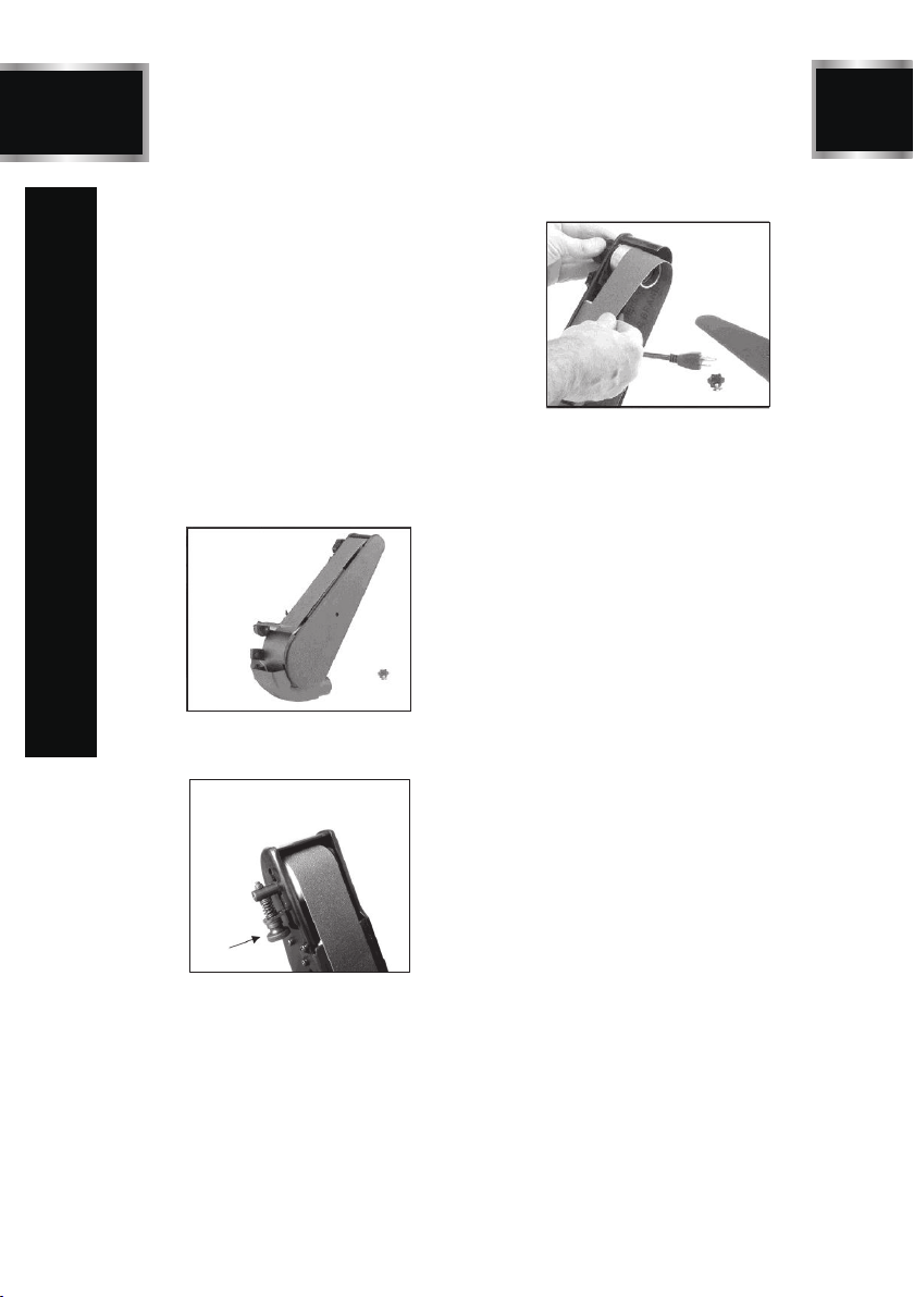
2. Remove the star knob from the right-
hand sanding belt cover as shown (in
Fig 13) and remove the cover.
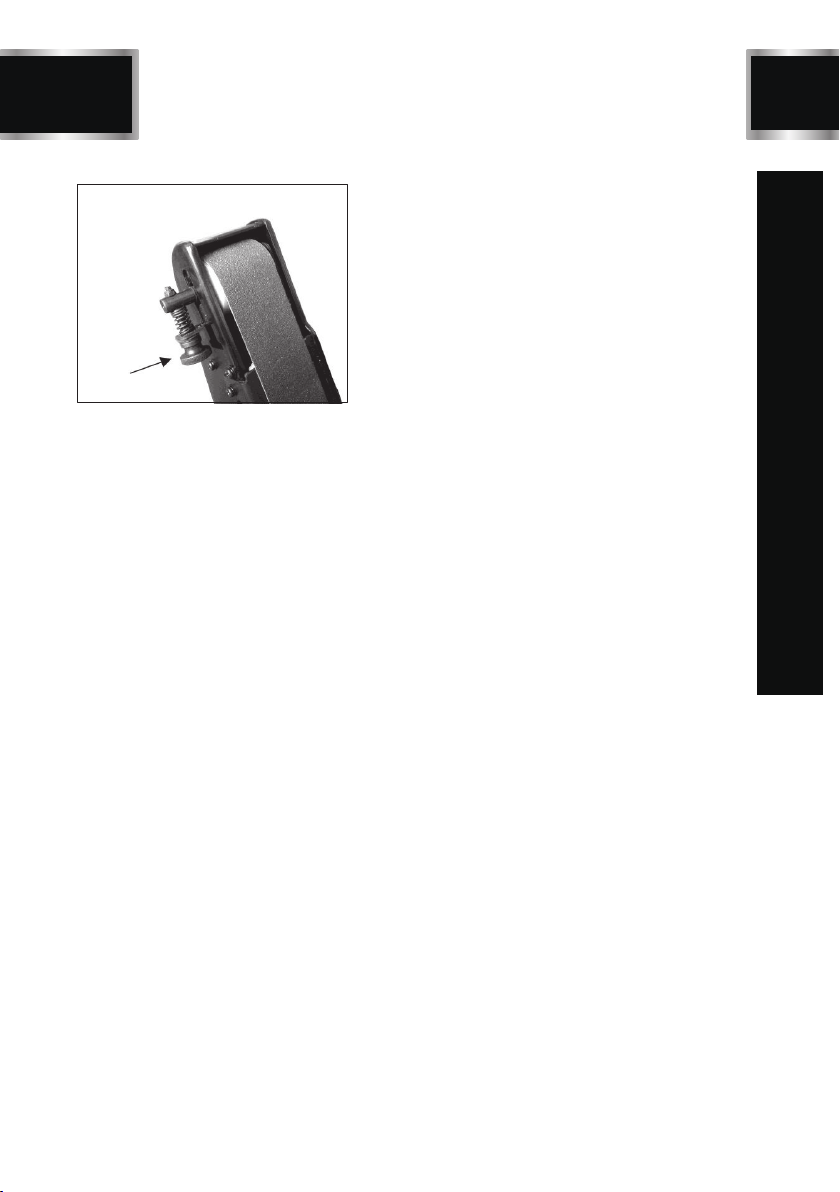
3. Loosen the sanding belt tension knob,
as shown (in Fig 14).
4. Pull the sanding belt tension knob down
with one hand and work the sanding belt
off the rollers with the other hand as
shown( in Fig15).
5. Install the new sanding belt in the reverse
order of removal and replace the belt
cover.
6. Track the new sanding belt before tu-
REPLACING SANDING BELT
Figure 13
Figure 14
Figure 15
rning the machine on (see Belt Tracking).
MAINTENANCE

16
BD4603 TLGS625
TROUBLESHOOTING GUIDE
Problem(s) Possible Cause(s) Suggested Solution(s)
Grinder won’t start.
1. Blown line fuse or tripped
circuit breaker.
2. Low line voltage.
3. Material wedged between
wheel and guard.
4. Defective switch.
5. Defective, blown capacitor.
6. Defective circuit board.
1. Replace with fuse of proper size, if
fuse is blown. Reset tripped breaker.
2.Check power supply for voltage and
correct as needed.
3.Turn grinder off and remove material.
4.Replace switch.
5.Replace capacitor
6.Replace circuit board.
Excessive
vibration.
1. Improper mounting of
grinder or accessories.
2.
Grinding wheel out of balance.
1. Remount bench grinder.
2.
Dress wheels or replace wheels.
Motor overheating.
1. Excess pressure required
to grind material.
2. Grinding on side of wheel.
3. Motor not turning freely
(without power).
1. Dress or replace wheels.
2.
Grind only on face of wheel.
3.
Clean around wheels and shaft
and/
or replace bearings.
Fuses are being
blown or circuit
breakers tripped.
1. Overloading due to binding.
2. Defective plug.
3. Defective cord.
4. Defective switch.
1.
Clean around wheels and shaft
and/
or replace bearings.
2. Replace plug.
3. Replace cord.
4. Replace switch.
Machine slows
when operating.
1. Depth of cut too great. 1. Slow down the rate of movement of
the workpiece into wheel.
Wavy condition on
1. Machine vibrating.
2. Workpiece not being held
firmly.
3. Wheel face uneven.
4. Wheel is too hard.
Make sure machines is securely
mounted on a solid surface.
2.
1.
Use a holdingdevice to firmly
retain the workpiece.
3. Dress the grinding wheel.
4. Use softer wheel, or reduce the
feed rate.
surface of workpiece.
Lines on surface of
workpiece.
1. Impurity on wheel surface.
2. Workpiece not being held
tightly.
1. Dress the grinding wheel.
2. Use a holding device to firmly retain
the w orkpiece.
1. Improper type of grinding
wheel.
2. Improper feed rate.
3. Coolant required.
Burning spots or
cracks in the
workpiece.
1. Try a wheel which is softer style
or a coarser grit.
2. Slow down the rate of movement
of the workpiece into w heel.
3. Add optional coolant system or
introduce coolant by hand .

BD4603
17 TLGS625
TROUBLESHOOTING GUIDE
Problem(s) Possible Cause(s) Suggested Solution(s)
Wheel dulls quickly,
grit falls off.
1. Depth of cut too great.
2. Wheel is soft.
3. Wheel diameter too small.
4. Bad wheel dress.
5. Defective wheel bonding.
1. Slow down the rate of movement
of the workpiece into w heel.
2. Wheel too soft for the material.
being ground, select harde r bond.
3. Replace the wheel.
4. Dress the wheel.
5. Consult manufacturer of grinding
wheel.
Wheel clogs and
workpiece shows
burn marks.
1. Wheel is too hard.
2. Feed rate too slow.
3. Bad wheel dress.
4. Coolant required.
1. Wheel too hard for the material
being ground, select softer bond .
2. Increase the rate of movement of
the workpiece into wheel.
3. Dress the wheel.
4. A dd optional coolant system or
introduce coolant by hand.

18
EXPLONED VIEW
TLGS625

BD4603
19 TLGS625
PARTS LIST
1 Philips Screw M5x 48 3
2 Left Guard Cover 1
3 Hex Nut, IType M12 Left 1
4 Flange 2
5 Grinding Wheel Φ150x20xΦ12.7 60#
6 Philips Screw +Spring Washer Assy. M5x10
7 Left Guard Assy. 1
8 Spark Deflect
9
10 Left Tool Rest 1
11 Flat Washer D8 4
12 Eyeshield Pressing Plate 1
13 Outer Hex Bolt M8X 10 2
14 Hex Nut M6 1
15 Switch 1
16 Philips Screw M4X 10 5
17 Left Eyeshield Bracket 1
18 Pressing Block 1
19 Hex Bolt M8X14 1
20 Eyeshield 1
21 Dome Screw M6X 16 1
22 Philips Screw M4x135 4
23 Flat Washer D4 4
24 End Caps 2
25 LED Bulb 12V0.36W 1
26 Philips Screw + Flat Washer +
Spring Washer Assy.
27 Outer toothed LockingWas her D4 2
28 Cord Bushing 1
29 Cord Clip 1
30 Flat Washer D10 1
31 Locking Nut M10 x1 1
32 Wavy Washer D35 1
33 Bearing 6202RZ 2
34 Stator 1
35 Rotor 1
36 Hex Nut M4 4
37 Power Cord 1
38 LED Assembly 1
39 Hex Bolt M5X20 1
40 Philips Screw M5X 8 4
41 Adjusting Screw 1
42 Hex Bolt M5X 10 2
43 Fixing Disc 1
44 Work Table Deflector 1
1
6
1
7
Philips Screw + Flat Washer +
Spring WasherAssy. M5x10
M4x8 3
45 Flat Washer D5 4
46 Limit Plate 1
47 Coolant Tray 1
48 Hex Nut M5 3
49 Hex Nut M4 2
50 Philips Screw M4 x8 4
51 Philips Screw + Spring Washer Assy. M6x18 2
52 Capacitor 16uF/300V 1
53 Compressing Spring 1
54 Work Table 1
55 Base Plate 1
56 Rubber Foot 4
57 Philips Screw + Flat Washer Assy. M4x12 4
58 Base 1
59 Switch Plate 1
60 Nut M5 2
61 Low Temperature Bearing 6200 2
62 Coolant Tray Clip 1
63 Idle Roller 1
64 Nut M12 1
65 Washer D10 1
66 Dust Cover 1
67 Bushing 2
68 Right Guard 1
69 Supporting Plate 1
70 Adjusting Spring 1
71 Hex Column Screw M5X12 4
72 Guide Frame Assy. 1
73 Philips Screw + SpringWasher Assy. M5X16 3
74 Rotating Disc 1
75 Belt 50x710 mm 80 # 1
76 Right Guard Cover 1
77 Pressing Plate 1
78 Driving Wheel 1
79 Knob M5X18 1
80 Hex Screw M6X 6 3
81 Big Flat Washer D5 4
82 ldling Shaft 1
83 Wrench 1
84 Nut M8 1
85 Rubber Washer 1
86 Capacitor support 1
87 Hex nut M8 1
88 Lamp cover 1
89 Bushing 1
Part Description Qty Description Qty
Part

20
BD4603 TLGS625
Having Problems ?
Give us a chance to help you before returning this product
Email :
After the phone:(844) 866-5687
ONE-YEAR LIMITED WARRANTY
WARRANTY
45 Flat Washer D5 4
46 Limit Plate 1
47 Coolant Tray 1
48 Hex Nut M5 3
49 Hex Nut M4 2
50 Philips Screw M4 x8 4
51 Philips Screw + Spring Washer Assy. M6x18 2
52 Capacitor 16uF/300V 1
53 Compressing Spring 1
54 Work Table 1
55 Base Plate 1
56 Rubber Foot 4
57 Philips Screw + Flat Washer Assy. M4x12 4
58 Base 1
59 Switch Plate 1
60 Nut M5 2
61 Low Temperature Bearing 6200 2
62 Coolant Tray Clip 1
63 Idle Roller 1
64 Nut M12 1
65 Washer D10 1
66 Dust Cover 1
67 Bushing 2
68 Right Guard 1
69 Supporting Plate 1
70 Adjusting Spring 1
71 Hex Column Screw M5X12 4
72 Guide Frame Assy. 1
73 Philips Screw + SpringWasher Assy. M5X16 3
74 Rotating Disc 1
75 Belt 50x710 mm 80 # 1
76 Right Guard Cover 1
77 Pressing Plate 1
78 Driving Wheel 1
79 Knob M5X18 1
80 Hex Screw M6X 6 3
81 Big Flat Washer D5 4
82 ldling Shaft 1
83 Wrench 1
84 Nut M8 1
85 Rubber Washer 1
86 Capacitor support 1
87 Hex nut M8 1
88 Lamp cover 1
89 Bushing 1
Table of contents
Other TOUGH-WORKS Sander manuals


Popular Sander manuals by other brands

DELMEQ
DELMEQ 706500AN instruction manual

Makita
Makita BO5020 technical information

Steel City
Steel City TITANIUM Series owner's manual

Dynabrade
Dynabrade Mini-Dynorbital Silver Supreme 69500 Safety, operation and maintenance manual

VITO
VITO PRO POWER VILGE710 instruction manual

Kalamazoo
Kalamazoo 2FSM instruction manual


