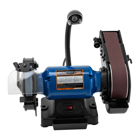
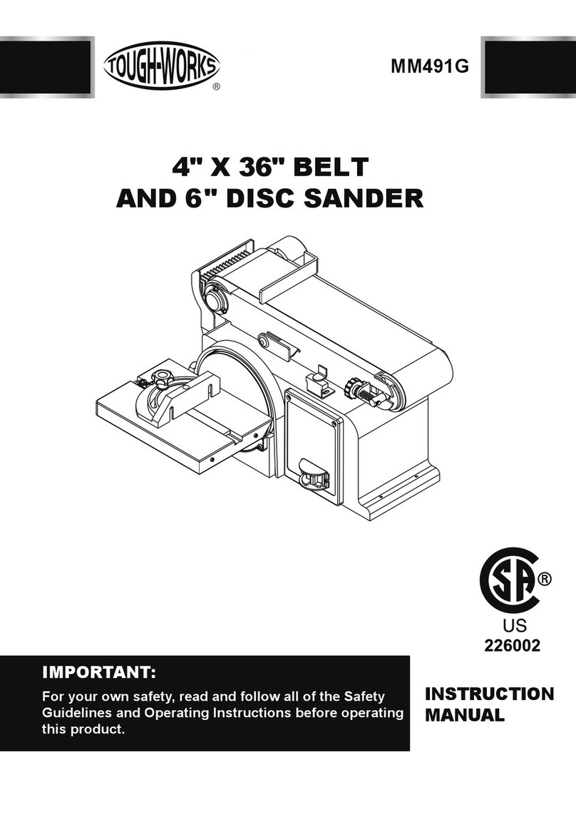
TOUGH-WORKS MM493B User manual

1" X 30" BELT
AND 5" DISC SANDER
INSTRUCTION
MANUAL
IMPORTANT:
For your own safety, read and follow all of the Safety
Guidelines and Operating Instructions before operating
this product.
MM493B

2
TABLE OF CONTENTS
SPECIFICATIONS
TABLE OF CONTENTS
BD4603
TABLE OF CONTENTS ...............................................................................................
2
SAFETY GUIDELINES ................................................................................................
4
PACKAGE CONTENTS ..............................................................................................
7
KEY PARTS DIAGRAN
..................................................................................................
8
ASSEMBLY/MOUNTING
........................................................................................
12
OPERATION .................................................................................................................
13
MAINTENANCE ............................................................................................................
14
TROUBLESHOOTING GUIDE .....................................................................................
16
EXPLONED VIEW .........................................................................................................
17
PARTS LIST ..................................................................................................................
19
WARRANTY ..................................................................................................................
20
ELECTRICAL SAFETY .................................................................................................
6
SPECIFICATIONS .......................................................................................................
2
Motor 120 VAC, 60 Hz, 2.3Amp,1/3HP
Phase Single
Disc Speed 3450RPM
Belt Speed 3270 SFPM
Belt Size
Belt Table dimensions 5-3/4" Dia.
Disc Table dimensions 7-3/16 x 3-7/8"
Tables tilt 0 to 45°
1" x 30"
MM493B

BD4603
SAFETY GUIDELINES
3
For your own safety, read and understand
all warnings and operating instructions before
using any tool or equipment.
Some dust created by power sanding, sawing,
grinding,drilling and other construction activities
contains chemicals known to the State of
California to cause cancer, birth defects or other
reproductive harm.
Some examples of these chemicals are:
• Lead from lead-based paints.
• Crystalline silica from bricks and cement and
other masonry products.
• Arsenic and chromium from chemically-treated
lumber.
Your risk from these exposures vary, depending
on how often you do this type of work. To reduce
your exposure to these chemicals:
work in a well ventilated area and work with
approved safety equipment. Always wear OSHA/
NIOSH approved, properly fitting face mask or
respirator when using such tools.
Always follow proper operating procedures as
defined in this manual even if you are familiar with
the use of this or similar tools. Remember that
being careless for even a fraction of a second can
result in severe personal injury.
WORK PREPARATION
• Wear proper apparel. Do not wear loose clothing,
gloves,neckties, rings, bracelets or other jewelry
which may get caught in moving parts of the tool.
• Wear protective hair covering to contain long
hair.
• Wear safety shoes with non-slip soles.
• Wear safety glasses complying with United
States ANSI Z87.1. Everyday glasses have only
impact resistant lenses. They are NOT safety
glasses.
• Wear face mask or dust mask if operation is
dusty.
• Be alert and think clearly. Never operate power
tools when tired, intoxicated or when taking
medications that cause drowsiness.
WORK AREA PREPARATION
• Keep work area clean. Cluttered work areas
invite accidents.
• Do not use power tools in dangerous en-
vironments. Do not use power tools in damp
or wet locations. Do not expose power tools
to rain.
• Work area should be properly lit.
• Proper electrical receptacle should be
available for tool. Three-prong plug should
be plugged directly into properly grounded,
three-prong receptacle.
• Extension cords should have a grounding
prong and the three wires of the extension
cord should be of the correct gauge.
• Keep visitors at a safe distance from work
area.
• Keep children out of the work area. Ensure
your work shop is child-proof. Use padlocks,
master switches or remove switch keys to
prevent any unintentional use of power tools.
TOOL MAINTENANCE
• Always unplug tool prior to inspection.
• Consult manual for specific maintaining
and adjusting procedures.
• Keep tool lubricated and clean for a safe
operation.
• Remove adjusting tools. Form habit of
checking to see adjusting tools or accessories
are removed before switching tool on.
• Keep all parts in working order. Check to
determine that guard or other parts will
operate properly and perform their intended
function.
• Check for damaged parts. Check for alig-
nment of moving parts, binding, breakage,
mounting and any other condition that may
affect tool’s operation.
• A guard or any other part that is damaged
should be properly repaired or replaced. Do
not perform makeshift repairs.
TOOL OPERATION
• Use the right tool for your job. Do not force
your tool or attachment to do a job for which
it was not designed.
• Avoid accidental start-up. Make sure that
MM493B

4
SAFETY GUIDELINES
the tool is in the “OFF" position before plugging
in.
• Know your tool. Learn the tool’s operation,
application and specific limitations before
using it.
• Sander MUST be used with Dust Collector to
capture dust.
• Disconnect tool when changing belt or abrasive
disc.
• Do not force tool. It will work most efficiently at
the rate for which it was designed.
• Keep hands away from moving parts and sanding
surfaces.
• Never leave tool running unattended. Turn the
power off and do not leave tool until it comes
to a complete stop.
• Do not overreach. Keep proper footing and
balance.
• Never stand on tool. Serious injury could occur
if tool is tipped or if belt or disc are unintenti-
onally contacted.
• Know your tool. Learn the tool’s operation,
application and specific limitations.
• Use recommended accessories(refer to page13).
Use of improper accessories may cause risk of
injury to persons.
• Handle the workpiece correctly. Protect hands
from possible injury.
• Turn machineoff if it jams. Belt jams when it
digs too deeply into workpiece.(Motor force keeps
it stuck in the work.)
• Support workpiece with miter gauge, belt platen
or work table.
• Maintain 1/16 ″ maximum clearance between
table and sanding belt or disc.
Think safety! Safety is a combination of operator
common sense and alertness at all times when
tool is being used.
Do not attempt to operate tool until it is completely
assembled according to the instructions.
CAUTION
MM493B

ELECTRICAL SAFETY
BD4603
5
Do not connect dust collector to the power source
until all assembly steps have been completed.
The motor is designed for operation on the
voltage and frequency specified. Normal loads will
be handled safely on voltages not more than 10%
above or below specified voltage. Running the
unit on voltages which are not within the range may
cause overheating and motor burn-out.
Heavy loads require that the voltage at motor
terminals be no less than the voltage specified
on nameplate.
Improper connection of equipment grounding
conductor can result in the risk of electrical
shock. Equipment should be grounded while
in use to protect operator from electrical shock.
• Check with a qualified electrician if you do not
understand grounding instructions or if you
are in doubt as to whether the tool is properly
grounded.
• This tool is equipped with an approved cord
rated at 120V and a 3-prong grounding type
plug (see Figure A)for your protection against
shock hazards.
• Grounding plug should be plugged directly
into a properly installed and grounded 3-prong
grounding typer eceptacle, as shown (see
Figure A).
• Do not remove or alter grounding prong in
any manner. In the event of a malfunction
or breakdown, grounding provides a path of
least resistance for electrical shock.
Properly Grounded Outlet
Grounding Prong
3-Prong Plug
Figure A
Do not permit fingers to touch the terminals of
plug when installing or removing from outlet.
•Plug must be plugged into matching outlet
that is properly installed and grounded in
accordance with all local codes and ordin-
ances. Do not modify plug provided. If it will
not fit in outlet, have proper outlet installed
by a qualified electrician.
•Inspect tool cords periodically, and if damaged,
have repaired by an authorized service facility.
• Green (or green and yellow) conductor in cord
is the grounding wire. If repair or replacement
of the electric cord or plug is necessary, do
not connect the green (or green and yellow)
wire to a live terminal.
• Where a 2-prong wall receptacle is enco-
untered, it must be replaced with a properly
grounded 3-prong receptacle installed in
accordance with National Electric Code and
local codes and ordinances.
This work should be performed by a qualified
electrician.
A temporary 3-prong to 2-prong grounding
adapter (see Figure B) is available for conn-
ecting plugs to a two pole outlet if it is properly
grounded.
MM493B
POWER SOURCE
GROUNDING INSTRUCTIONS
Figure B
• Do not use a 3-prong to 2-prong grounding
adapter unless permitted by local and national
codes and ordinances. (A 3-prong to 2-prong
grounding adapter is not permitted in Canada.)
Where permitted, the rigid green tab or terminal
on the side of the adapter must be securely
connected to a permanent electrical ground
such as a properly grounded water pipe, a
properly grounded outlet box or a properly

6
C
EXTENSION CORDS
• The use of an extension cord is not reco-
mmended.
The use of any extension cord will cause some
drop in voltage and loss of power.
• Wires of the extension cord must be of
sufficient size to carry the current and maintain
adequate voltage.
• Use the table to determine the minimum wire
size(A.W.G.) extension cord.
• Use only 3-wire extension cords having 3-
prong grounding type plugs and 3-pole rec-
eptacles which accept the tool plug.
• If the extension cord is worn, cut or damaged
in any Extension Cord Length.
Extension Cord Length
Wire Size…………….. 18 A.W.G.
Up to 25 ft. . . . . . . . . . . . . . . . . . . . 18
25 to 50 ft. . . . . . . . . . . . . . . . . . . . . .16
NOTE: Using extension cords over 50 ft. long
is not recommended.
MOTOR
The sander is assembled with motor and wiring
installed.The electrical wiring schematic is
shown in Figure B.
Horsepower (Continuous Duty) 1/3
Voltage 120
Amp 2.3
Hertz 60
Phase Single
RPM 3450
ELECTRICAL CONNECTIONS
off and disconnected from power source while
motor is mounted, connected, reconnected
or anytime wiring is inspected.
Motor and wires are installed as shown in
wiring schematic (See Figure C). Motor is ass-
embled with approved, 3-conductor cord to be used
at 120 volts.
The power lines are inserted directly into the
switch. The green ground line must remain
securely fastened to the frame to properly
protect against electrical shock. The power
supply to the motor is controlled by a single
pole locking rocker switch.
• Remove the key to prevent unauthorized
use.
ELECTRICAL SAFETY
Figure C
MM493B
grounded wire system.
• Many cover plate screws, water pipes and
outlet boxes are not properly grounded. To
ensure proper ground, grounding means must
be tested by a qualified electrician.
MOTOR SPECIFICATIONS:
All electrical connections must be performed
by a qualified electrician. Make sure tool is

BD4603
7
PACKAGE CONTENTS
No. Description Qty.
1
2
3
4
5
6
7
8
9
10
1
1
1
1
1
2
2
1
1
1
Sander Assembly with Abrasive Belt and Disc
Sanding Disc Table
Miter Gauge
Sanding Belt Table
Dust Chute (with dust nozzle adapter)
Locking Knobs (sanding disc table)
Washers (sanding disc table)
Washer 8 mm (Sanding Belt Table)
Locking Lever (Sanding Belt Table)
Hex Wrench
MM493B
1
23
4
10
5
6789

8
KEY PARTS DIAGRAN
Sanding Belt
Locking Lever
Switch
Enclosed Induction
Motor
Dust Chute
Cast AL Base
MM493B
Sanding Belt Table Sanding Disc
Sanding Disc
Table

9
ASSEMBLY/MOUNTING
Figure D
MM493B
Do not use the machine until it is completely
assembled and you have read and understood
the entire operating manual.
ASSEMBLE THE DUST CHUTE
Refer to Figure D
Slide the groove in the dust chute onto the sanding
disc guard casting as shown. Secure the dust
chute to the sander with screws, flat washers and
spring washers supplied. Ensure the dust chute
opening faces the rear of the unit.
Dust Chute
ScrewsFlat
Washers
Washers
Groove
Sanding Disc
ASSEMBLE THE SANDING
DISC TABLE
Refer to Figure E,F
Align the sanding disc table to the sanding disc
guard.
Align the pins on the sanding disc table with slots
on the sanding disc guard. Slide the pins in and
up into the slot.
Place a washer on each locking knob.
While holding the sanding disc table in place,
thread a locking knob into the slot on each side
of the table.Tighten each locking knob.
Sanding Disc
Guard
Slot
Hole for
Locking
Knob
Locking
Knob and
Washer
Sanding
Disc
Table
Pins
Figure E
To adjust sanding disc table
Place a square on the table with the ruler side
against the sanding disc. The table should be
90° to the sanding disc.
If the table is not 90° to the sanding disc, loosen
the locking knobs and tilt table up and down
until it is 90° to the sanding disc. Tighten locking
knobs securely.Recheck adjustment using
the square.
For bevel sanding, loosen the locking knobs
and tilt table up and down between 0 – 45° to
desired angle.
Sanding
Disc Table
Locking
Knob
Figure F
ASSEMBLE THE SANDING
BELT TABLE
Refer to Figure G–K
Use the 4 mm hex wrench supplied to disa-
ssemble the locking lever assembly. (bolt,
spring, lever and shaft,see Figure G).
Pass the sanding belt/backstop through the
slot of the sanding belt table and position the
table as shown.
Use the washer and shaft from the locking
lever assembly to secure the sanding belt table
to the frame.
The shaft should be placed at the rear of the
adjusting slot as shown in Figure H
Reassemble the screw, spring and lever to
the shaft. Tighten the locking lever fully to lock
the table.
Figure G
Sanding
Belt
Sanding Belt Table
Slot

10
MM493B
To adjust sanding belt table:
To square
If using the backstop, make sure it just touches
the back of the belt. If adjustment is needed,
see Backstop paragraph.
Adjusting
Slot Shaft Screw
Spring
Lever
Washer
Figure H
Remove the upper guard, loosen the lock knob
and slide the guard up and off the belt. See Figure I.
Place a square on the table against the belt as
shown.
Loosen the locking lever assembly and adjust
until square.
Retighten the locking lever.
Belt Guard
Lock Knob
Upper Belt
Guard
Figure I
56
7
4 3 2 1
21 3 4 5 6 7
Leveling Screw
Sanding
Belt
Table Locking
Lever
Backstop
Sanding Belt
Figure J
To level
A leveling screw is provided to aid in leveling
the belt disc table.
Once the belt table is square, use the 4 mm
hex wrench provided to adjust the hex screw
down until it touches the frame (under the table),
then lock the screw in place by tightening the
nut under the table using an 11 mm wrench.
To set at 45°
If needed the table may be tilted.
• Loosen the locking lever until it is very loose.
• Slide locking lever to the front of the adjusting
slot as shown to tilt the table.
• Tighten the lock lever.
After all adjustments are made replace the upper
guard and tighten the lock knob.
Sanding Belt
Table
Lever
Adjusting
Slot
Figure K
REPLACING THE SANDING BELT
Refer to Figure L, M
NOTE: This sander uses 1" x 30" sanding belts.
Turn the machine "OFF", and disconnect the
machine from the power source before assem-
bling the sanding belt.
Remove the belt guard locking knob and upper
belt guard. Remove the screws securing the side
belt guard and then remove the side belt guard.
See Figure L.
Hold and apply moderate pressure to the belt
tracking knob assembly to release the belt tension
enough to remove the old belt.
NOTE: The belt tracking knob is spring loaded.
Position the new belt on the wheels. Applying
pressure to the belt tracking knob will release
tension allowing the belt to be assembled over
he middle wheel. Make sure the directional arrows
on the belt point in the samedirection as the arrows
on the sander.
If needed, turn the belt tracking knob clockwise
until the belt tracks to the center of the wheels.
Replace the upper, side, and lower guards and
secure in place with the belt guard lock knob and
Belt Guard
Locking
Knob
Upper Belt
Guard
Side Belt
Guard
Figure L
ASSEMBLY/MOUNTING

BD4603
11
ASSEMBLY/MOUNTING
MM493B
Sanding
Belt
Belt
Tracking
Knob
Wheel
Middle
Wheel Wheel
Figure M
secure in place with the belt guard lock knob
and lower guard screws.
Ensure the sanding belt table is level. To
adjust see the To Adjust Sanding Belt Table
paragraph in this section.
BACKSTOP
The backstop is a surface to sand against.
To Adjust
Remove the sanding belt table. See Mount
the Sanding Belt Table paragraph and reverse
the order of assembly.
Loosen the two screws on backstop and slide
the backstop in or outuntil it just touches the
back of the belt. Retighten the two screws and
replace the sanding belt table. See Mount the
Sanding Belt Table paragraph.
To Remove
The backstop can be removed for polishing
and contour sanding.
Remove thesanding belt table. See Mount
the Sanding Belt Table paragraph and reverse
the order of assembly.
Remove screws and washers securing backstop.
Place screws, washers and backstop in a safe
place for future use.
Replace the sanding belt table. See Mount the
Sanding Belt Table paragraph.
Screws and
Washers
Backstop
Figure N
SANDING BELT TRACKING
ADJUSTMENT
Refer to Figure L, M
Turn the machine "OFF", and disconnect the
machine from the power source.
Remove the belt guard locking knob and upper
belt guard. Remove the screws securing the
side belt guard and then remove the side belt
guard. See Figure L.
Rotate the sanding belt by hand to check the
belt tracking. The belt should track to the center
of the wheels.
– When looking at the front of the sander if
the belt tracks to the left, turn the tracking
knob counterclockwise until the belt tracks
to the center of the wheels.
– When looking at the front of the sander if
the belt tracks to the right, turn the tracking
knob clockwise until the belt tracks to the
center of the wheels.
Replace the upper and side belt guards and
secure in place with the belt guard locking
knob.
Plug the power cord into the correct receptacle.
(Refer to Power Source paragraph in this section
of the manual.)
Turn the switch ON and OFF to make sure the
belt is tracking at high speed; readjust with
tracking knob if needed.
DUST PORT OPTIONS
Refer to Figure O
The dust ports can be easily connected to a dust
collection system with a large diameter shop
vacuum hose.
Sanding operations are inherently dusty. This
sander is equipped with two 1-3/4” OD x 1-1/2”
ID dust ports to help minimize the amount of
dust escaping into the surrounding air. Attach
the dust collection system vacuum hose to the
dust chute.
NOTE: The dust chute is shipped with an
adapter for use with smaller hose dust colle-
ctors. This adapter has a 1-1/4” ID and can be
used in either dust port.

12
BD4603 MM493B
NOTE: The use of a dust collection system
is strongly recommended when using the
belt/disc sander. Use of a mask or respirator
is still recommended even when using a dust
collection system.
Dust Port
Adapter
Dust Port
Adapter
Dust Port
Dust Port
Figure O
ASSEMBLY/MOUNTING

BD4603
13
OPERATIONS
MM493B
ON/OFF SWITCH
Refer to Figure P
To turn sander ON place the ON/OFF switch
in the ON position.
To turn the sander OFF, place the ON/OFF
switch in the OFF position.
SURFACE SANDING ON
SANDING BELT
Hold the workpiece firmly with both hands.
Keep fingers away from sanding belt. Keep
the workpiece end against the backstop and
move it slowly across the sanding belt. Apply
enough pressure to remove material; excessive
pressure will reduce sanding efficiency.
END SANDING - DISC/BELT
Refer to Figure Q
Use end sanding when sanding the ends of
small, narrow workpieces and outside curved
edges.
Always work on the left side of the disc (do-
wnward rotation side), holding the workpiece
firmly with light pressure against the sanding
disc.
ON/OFF
Switch
Figure P
To avoid personal injury and/or damage to the
workpiece,become familiar with the rotation
of the sanding belt and disc surfaces.
The sanding belt rotates counterclockwise or
downward toward the table or backstop. The
sanding disc rotates counterclockwise, downward
toward the work table on the left side of the
sanding disc and upward from the work table
CAUTION
on the right side of the sanding disc. Always
use the left side of the sanding disc; using
the right side of the sanding disc will cause
the workpiece to fly up or kickback
MITER GAUGE - DISC SANDER
Refer to FigureQ
A miter-gauge is supplied with your sander,
and can be used on the sanding disc table.
Place the miter gauge slide pole into the slot
on the work table.
Loosen the miter gauge lock knob and move
the miter gauge head to the left or right to
the desired position.
Tighten the miter gauge lock knob.
NOTE: The miter gauge head can be moved
right or left 0 to 60º.
NOTE: Use of the miter gauge is recom-
mended for sanding small end surfaces on
the sanding disc.
NOTE: Always move the workpiece across
the sanding disc from the left side towards
the right side, and be sure to hold the wo-
rkpiece firmly onto the table surface.
CONTOUR SANDING WITH
THE BELT
With the backstop removed the sanding belt
conforms to a curved edge for sanding and
polishing.
Remove the backstop. See Backstop under
Assembly.
Turn the sander ON and slowly feed it into
the sanding belt.
Slot On Work Table
Lock Knob
Miter Gauge
Figure Q

14
MAINTENANCE
MM493B
Make certain that the unit is disconnected
from power source before attempting to service
or remove any component.
CLEANING
Keep machine and workshop clean. Do not
allow sawdust to accumulate on the tool. Keep
the wheels clean. Dirt on the wheels will cause
poor tracking and belt slippage.
Periodically empty the dust collection bag/
canister and clean the filters on your dust
collector (not included) to keep dust collection
at maximum efficiency. Be certain motor is
kept clean and is frequently vacuumed free of
dust.
Use soap and water to clean painted parts,
rubber parts and plastic guards.
LUBRICATION
The shielded ball bearings in this tool are
permanently lubricated at the factory. They
require no further lubrication.
• When operation seems stiff, a light coat of
paste wax applied to the table will make it
easier to feed the work while finishing.
• Do not apply wax to the belt platen. Belt could
pick up wax and deposit it on wheels causing
belt to slip.
• Slide the new belt over the drive and idler
wheels; then center the belt on the wheels.
NOTE: There may be an arrow on the inside
of the belt. The arrow should point in the di-
rection of belt travel to ensure that the splice
in the belt will not come apart.
KEEP TOOL IN REPAIR
• If power cord is worn, cut, or damaged in any
way, have it replaced immediately.
• Replace worn abrasives when needed.
• Replace any damaged or missing parts. Use
parts list to order parts.
Any attempt to repair motor may create a
hazard unless repair is done by a qualified
service technician.

TROUBLESHOOTING
BD4603
15
PROBLEM PROBLEM CAUSE SUGGESTED CORRECTIVE ACTION
1. Sanding belt/disc has
been stored in an incorrect
environment.
2. Sanding belt/disc has
been damaged or folded.
1. Ensure sanding accessories are
stored away from extremely hot or
dry temperatures.
2. Store sanding accessories flat – not
bent or folded.
1. Sanding belt/disc grit is
too coarse for the desired
finish.
2. Workpiece sanded
across the grain.
3. Too much sanding force
on the workpiece.
4. Workpiece held still
against the belt/disc for
too long.
Motor will not
start –fuses or
circuit breakers
tripping or
blowing.
Sanding Grains
easily rub off
belt or discs.
Deep sanding
grooves or scars
in workpiece.
1. Use a finer-grit sanding accessory.
2. Sand with the grain of the wood.
3. Reduce pressure on workpiece while
sanding.
4. Keep workpiece moving while sanding
on the sanding accessory.
MM493B
Sanding surface
clogs quickly.
1. Too much pressure
against belt/ disc.
2. Sanding softwood.
1. Reduce pressure on workpiece while
sanding.
2. Use different stock, different sanding
accessories, or accept that this will happen
and plan on cleaning or replacing discs/
belts frequently.
1. Using a sanding grit
that is too fine.
2. Using too much pressure.
3. Work held still for too
long.
1. Use a coarser-grit sanding accessory.
2. Reduce pressure on workpiece while
sanding.
3. Do not keep workpiece in one place
for too long.
Burns on
workpiece.
1. Short circuit in line,
cord or plug.
2. Short circuit in motor
or loose connections.
3. Incorrect fuses or circuit
breakers in power line.
1. Inspect cord or plug for damaged
insulation and shorted wires.
2. Inspect all connections on motor for
loose or shorted terminals and/or worn
insulation.
3. Install correct fuses or circuit breakers
or switch tool to an appropriately size
circuit.
Workpiece lifts up
from the sanding
disc/table.
Sanding on the “up” side
wheel.
Sand on right side of sanding disc
(as operator faces the disc).

16
BD4603 MM493B
TROUBLESHOOTING
PROBLEM PROBLEM CAUSE SUGGESTED CORRECTIVE ACTION
1. Sanding belt/disc has
been stored in an incorrect
environment.
2. Sanding belt/disc has
been damaged or folded.
1. Ensure sanding accessories are
stored away from extremely hot or
dry temperatures.
2. Store sanding accessories flat – not
bent or folded.
1. Short circuit in motor
or loose connections.
2. Low voltage.
3. Incorrect fuses or
circuit breakers in
power line.
4. Motor overload.
Machine
vibrates
excessively.
Sanding Grains
easily rub off
belt or discs.
Motor stalls
(resulting in
blown fuses
or tripped
circuit).
1. Inspect connections on motor for
loose or shorted terminals or worn
insulations.
2. Correct low voltage conditions (for
example: improper extension cord
length and/or gauge).
3. Install CORRECT fuses or circuit
breakers or plug tool into an appropriate
circuit, matched to an appropriate fuse
or breaker.
4. Reduce the load on the motor.
Motor overheats.
1. Motor overloaded.
2. Extension cord too long
and of insufficient gauge
(weight).
1. Reduce load on motor (pressure on
object being sanded).
2. Utilize an extension cord of appropriate
gauge and length or plug tool directly into
outlet.
1. Rubber feet worn,
mounting hardware loose
2. Workbench or table is
not level
3. Worn bearings
1. Replace the rubber feet, tighten
mounting hardware.
2. Shim or adjust as need.
3. Have bearings replaced by service
technician.
Machine slows
when operating.
1. Feed rate too great.
2. Undersized circuit or
use ofundersized extension
cord.
1. Reduce the rate at which the workpiece
is fed into the working area of the tool.
2. Ensure circuit wires or extension cords
are proper gauge, or eliminate use of
extension cords.
Workpiece
frequently
gets pulled out
of operator’s
hands.
1. Not supporting the
workpiece against the stop.
2. Attempting to sand
(unaided) a workpiece that
is too small.
1. Use the platen (backstop) or miter
gauge to support the workpiece.
2. Use another hand tool or jig to grasp
or hold the workpiece.

BD4603
17 MM493B
EXPLODED VIEW

PARTS LIST
ID Description Size Q’ty
18
MM493B
Phillips Screw +Spring Washer M6x18
Rubber Foot
Phillips Screw +Flat Washer M4x12
Base Plate
Base
Switch Plate
Phillips Screw M5x10
End Cap
Wave Washer 35
Capacitor
Toggle with Safety Switch
Phillips Screw +Washer+Spring Washer M4x8
Stator
6P4 Line Clip
Power Cord
Capacitor Support
Hex Nut M8
Hex Nut M6
Belt Guard Plate
Rotor
Phillips Screw M4x8
Sanding Belt Platen
Flat Washer D4
Hex Nut M4x10
Cover Locking Knob
Sanding Belt Safeguard
Sanding Belt Bracket Cover
Sanding Belt 1”x30” 100 Grit
Idler Wheel
Clip Spring Washer D15
Bearing 6202
Idler Shaft
Hex Socket Screw M6x8
Philips Screw + Lock Washer M5x16
Connection Tube
Driven Wheel
Phillips Screw M6x10
1
2
3
4
5
6
7
8
9
10
11
12
13
14
15
16
17
18
19
20
21
22
23
24
25
26
27
28
29
30
31
32
33
34
35
36
37
2
4
4
1
1
1
4
1
1
1
1
2
1
1
1
1
2
1
1
1
1
1
5
2
1
1
1
1
2
2
4
1
1
1
1
1
3
PARTS LIST

WARRANTY
19 MM493B
PARTS LIST
ID Description Size Q’ty
38
39
40
41
42
43
44
45
46
47
48
49
50
51
52
53
54
55
56
57
58
59
60
61
62
63
64
65
66
67
68
69
70
71
72
73
74
1
1
1
1
1
1
1
1
1
1
1
1
4
1
1
1
2
1
1
1
1
1
1
4
1
1
1
2
2
1
1
3
1
1
4
3
1
Hex Bolt M10x25
Sanding Belt Support
Hex Socket Screw M6x20
Belt Sanding Table
Large Flat Washer D8
Ratchet Handle
Adjusting Shaft Guard
Adjusting Spring
Locking Nut M10
Adjusting Fixing Board
Adjusting Spring Ⅰ
Adjusting Knob
Phillips Screw ST4.2x16
Spring Column Pin φ3x20
Adjusting Shaft
Adjusting Spring Ⅱ
Large Flat Washer D5
C-Clip 3.5
Sanding Disc Cover
Indication Arrow
Toothed Washer D4
Phillips Screw +Flat Washer M4x6
Miter Gauge Knob
Hex Nut M4
Miter Gauge
Rod
Sanding Disc Table
Flat Washer D6
Table Locking Knob
Sander Paper Disc 5” / 80 Grit
Hex Socket Screw + Washer M6x16
Phillips Screw M4x10
Aluminum Disc
Disc Safeguard
Phillips Screw + Flat Washer M4x153
Phillips Screw + Flat Washer M4x8
Cord Clip

Having Problems ?
Give us a chance to help you before returning this product
Email :
After the phone:(844) 866-5687
ONE-YEAR LIMITED WARRANTY
PARTS LIST
20
MM493B
WARRANTY
Table of contents
Other TOUGH-WORKS Sander manuals
