TOUGH-WORKS MM491G User manual
IMPORTANT:
For your own safety, read and follow all of the Safety
Guidelines and Operating Instructions before operating
this product.
MM491G
4" X 36" BELT
AND 6" DISC SANDER
INSTRUCTION
MANUAL


2
TABLE OF CONTENTS
SPECIFICATIONS
TABLE OF CONTENTS
BD4603
TABLE OF CONTENTS ...............................................................................................
2
SAFETY GUIDELINES ................................................................................................
4
PACKAGE CONTENTS ..............................................................................................
6
KEY PARTS DIAGRAN
..................................................................................................
7
ASSEMBLY/MOUNTING
........................................................................................
9
OPERATION .................................................................................................................
11
MAINTENANCE ............................................................................................................
12
TROUBLESHOOTING GUIDE .....................................................................................
13
EXPLONED VIEW .........................................................................................................
14
PARTS LIST ..................................................................................................................
17
WARRANTY ..................................................................................................................
18
ELECTRICAL SAFETY .................................................................................................
5
SPECIFICATIONS .......................................................................................................
2
Motor 120 VAC, 4.3A, 60 Hz, 1/2 HP
Disc Size 6"
Belt Size 4 x 36"
Tables Tilt 0 to 45°
Belt Speed 1800 SFPM
Tables Size 9" x 6-1/4"
MM491G
DiscSpeed 3450 RPM

BD4603
SAFETY GUIDELINES
3MM491G
IMPORTANT! Safety is the single most
important consideration in the operation of
this equipment. The following instructions
must be followed at all times.
There are certain applications for which this tool
was designed.We strongly recommend that this
tool not be modified and/or used for any other
application other than that for which it was de-
signed. If you have any questions about its
application, do not use the tool until you have
contacted us and we have advised you.
General Safety Warnings
KNOW YOUR POWER TOOL.Read the owner’s
manual carefully. Learn the tool’s applications,
work capabilities, and its specific potential
hazards.
ALWAYS GROUND ALL TOOLS.
If your tool is equipped with a three
-pronged plug,you must plug it into
a three-hole electric receptacle. If
you use an adapter to accommodate a two-pro
nged receptacle, you must attach the adapter plug
to a known ground. Never remove the third prong
of the plug.
ALWAYS AVOID DANGEROUS
ENVIRONMENTS.
Never use power tools in damp or wet locations.
Keep your work area well lighted and clear of
clutter.
ALWAYS REMOVE THE ADJU-
STING KEYS AND WRENCHES
FROM TOOLS AFTER USE.
that keys and adjusting wrenches are removed
from the tool before turning it on.
Form the habit of checking to see
ALWAYS KEEP YOUR WORK AREA CLEAN.
Cluttered areas and benches invite accidents.
ALWAYS KEEP VISITORS AWAY
FROM RUNNING MACHINES.
All visitors should be kept a safe
distance from the work area.
ALWAYS MAKE THE WORKSHOP
CHILDPROOF.
Childproof with padlocks, master switches,or
by removing starter keys.
NEVER OPERATE A TOOL
WHILE UNDER THE INFLUENCE
OF DRUGS, MEDICATION, OR
ALCOHOL.
ALWAYS WEAR PROPER
APPAREL.
Never wear loose clothing or
jewelry that might get caught in
moving parts. Rubber-soled footwear is recom-
mended for the best footing.
ALWAYS USE SAFETY
GLASSES AND WEAR
HEARING PROTECTION.
Also use a face or dust mask if
the cutting operation is dusty.
NEVER OVERREACH.
Keep your proper footing and
balance at all times.
NEVER STAND ON TOOLS.
Serious injury could occur if the
tool is tipped or if the cutting tool
is accidentally
ALWAYS DISCONNECT TOOLS
Disconnect tools before servicing
and when changing accessories
such as blades, bits, and cutters
ALWAYS AVOID ACCIDENTAL STARTING.
Make sure switch is in “OFF” position before
plugging in cord.
NEVER LEAVE TOOLS RUNNING UNATTENDED.
ALWAYS CHECK FOR
DAMAGED PARTS.
Before initial or continual use of
the tool,a guard or other part that
is damaged should be checked to
assure that it will operate properly and perform
its intended function. Check for alignment of
moving parts, binding of moving parts, breakage
of parts,mounting, and any other conditions that
may affect its operation. A guard or other dama-
ged parts should immediately be properly repair-
ed or replaced.

4
SAFETY GUIDELINES
MM491G
Special Safety Rules For Belt
& Disc Sanders
1. Do not operate this machine until you have
read all of the following instructions.
2. Do not attempt to operate this machine until
it is completely assembled.
3. Do not turn ON this machine if any pieces
are missing.
4. If you are not familiar with the operation of
the machine, obtain assistance from a qual-
ified person.
5. It is highly recommended that this machine
be firmly mounted to a flat and secure work
surface or stand.
6. Always wear protective eyewear prior to op-
erating this machine.
7. Do not operate this machine if you are under
the influence of drugs and/or alcohol.
8. Remove all jewelry prior to operating this
machine.
9. Do not wear any gloves while operating this
machine.
10. Always make sure the power switch is in the
OFF position prior to plugging in the machine.
11. Always make sure the power switch is in the
OFF position when doing any assembly or
setup operation.
12. Always wear a dust mask and use adequate
dust collection and proper ventilation. Use of
sanders can produce harmful particles while
sanding certain types of woods.
13. The use of any accessories or attachments
not recommended may cause injury to you and
damage your machine.
14. This machine must be properly grounded.
15. Abrasive discs and belts should be the rec-
ommended width and length of the manufa-
cturer.
16. Always keep your face and hands clear of
moving parts such as belts and pulleys.
17.Keep power supply cords free of moving parts
of the sander. Damaged cords can result in
electric shock.
18. Maintain a 1/16” clearance between the sa-
nding disc, sanding belt and tables
19.Always support the workpiece with the table
or backstop.
20. Remove material or debris from the work area.
Keep work area neat and clean.
21.Keep these instructions for future reference.

ELECTRICAL SAFETY
BD4603
5
WIRING DIAGRAM
The machine must be grounded.
MM491G
In the event of a malfunction or breakdown,
grounding provides a path of least resistance
for electric current to reduce the risk of ele-
ctric shock. This tool is equipped with an electric
cord having an equipment-grounding conductor
and a grounding plug.The plug must be plugged
into a matching outlet that is properly installed
and grounded in accordance with all local codes
and ordinances.
Do not modify the plug provided. If it will not
fit the outlet, have the proper outlet installed
by a qualified electrician.
Improper connection of the equipment-grou
nding conductor can result in a risk of electric
shock. The conductor, with insulation having
an outer surface that is green with or without
yellow stripes, is the equipment-grounding
conductor. If repair or replacement of the ele-
ctric cord or plug is necessary, do not connect
the equipment-grounding conductor to a live
terminal.
Check with a qualified electrician or service
personnel if the grounding instructions are
not completely understood, or if in doubt as
to whether the tool is properly grounded.
Use only three wire extension cords that have
three-prong grounding plugs and three-pole
receptacles that accept the tool’s plug.
Repair or replace a damaged or worn cord
immediately.
This tool is intended for use on a circuit that
has an outlet that looks the one illustrated in
Figure A below.The tool has a grounding plug
that looks like the grounding plug as illustra-
ted in Figure A below. A temporary adapter,
which locks like the adapter as illustrated in
Figure B below, may be used to connect this
plug to a two-pole receptacle, as shown in Figure
B if a properly grounded outlet is not available.
The temporary adapter should only be used
until a properly grounded outlet can be installed
by a qualified electrician. The green colored
rigid ear or tab, extending from the adapter,
must be connected to a permanent ground
such as a properly grounded outlet box.
* Canadian electrical codes require extension
cords to be certified SJT type or better.
**Use of an adapter in Canada is not acceptable.
Replacement of the power supply cable should
only be done by a qualified electrician.
Fig.C
6
C
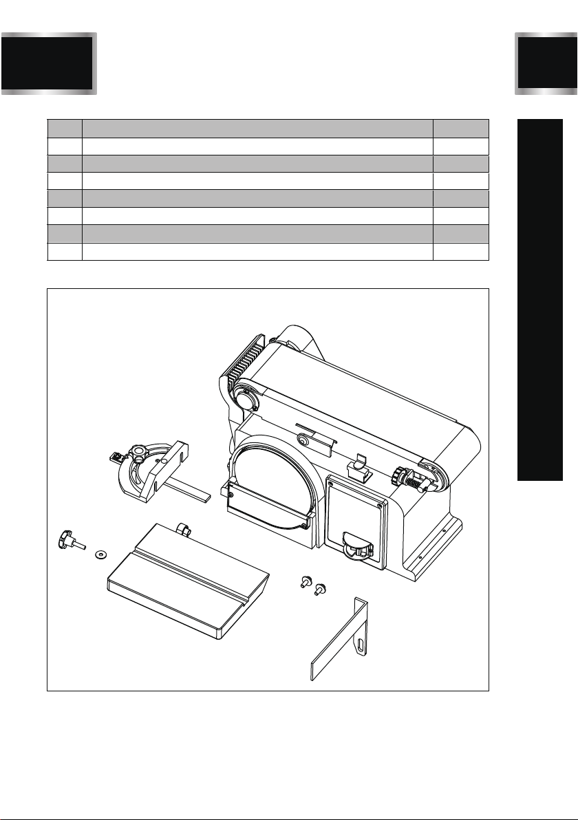
PACKAGE CONTENTS
No. Description Qty.
1
2
3
4
5
6
7
1
1
1
1
1
2
1
Sander Body
Miter Gauge
Work Table
Miter Gauge Knob
Big Flat Washer
Hex Socket Round Head Screw
Limited plate
MM491G
1
2
3
4
5
6
7Figure D
BD4603
7
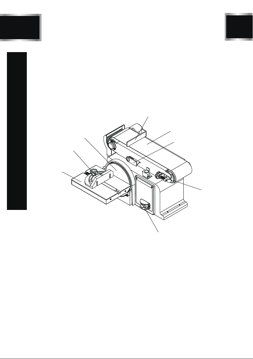
KEY PARTS DIAGRAN
Miter Gauge
MM491G
Work Table
Sander Belt
Sander Disc
Belt Tension Knob
Switch
Limited plate
Belt Adjustable Knob
8
ASSEMBLY/MOUNTING
MM491G
Securing Sander Base Assembly
to Workbench
Belt and disc sander must be fastened securely
to a firm supporting surface such as a wo-
rkbench.
1. Place sander in operational position on
workbench.
2. Place a pencil through the holes in the sander
base (42) and mark drill holes in workbench.
3. Remove sander and drill two10mm(3/8”)dia.
holes through the workbench.
4. Align sander base over holes and secure using
two 5/16” screws and hex. nuts
Figure E
Mounting Sanding Disc and Guard
1. Locate sanding disc (7) and peel backing off
disc.
2. Align perimeter of sanding disc over plate.
When aligned, press sandpaper disc firmly
onto backing disc.
3. Position disc guard (6) onto lower portion of
sanding disc so that the mounting holes align.
4. Using a Phillips screwdriver, fasten two pan
head screws (found in parts bag) over disc
guard.
Installing Work support
1. Place work support (60) over sanding belt as
shown in following illustration.
2. Place the hex. screw (91) through the flat
washer (90)and secure. Do not over tighten.
Table Support Assembly
1. Locate the table support (33) and hex. screws
(31) and washers (32).
2. Stand table (35) on its side, aligning holes as
shown in below illustration.
3. Fasten table support to table. Do not over
tighten screws.
4. Position table support (33) in corresponding
holes on side of base as shown in below
illustration.

BD4603
9MM491G
ASSEMBLY/MOUNTING
5. Place washer (32) on knob (34) shaft and
insert through slot into threaded holes in base.
6. Loosen the three hex. screws (31) and adjust
table so that there is a maximum of 1.5mm
(1/16”) space between the sanding disc and
the table. Tighten screws.

10
OPERATIONS
MM491G
Remounting Table for
Vertical Sanding
1. Remove backstop lock bolt and remove work
support.
2. Unscrew knob (34) and remove.
3. Pull table support (33) index pin out of mo-
unting hole.
4. Loosen hex socket screw (75) and raise
sanding bed to the desired sanding position.
5. Insert the table index pins into the auxiliary
(upper) holes in the sanding bed.
6. Tighten hex socket screw (75). Make sure
table is not touching sanding belt.
Leveling Table Assembly
1. Place a combination square on the table (35)
so that it also touches the sanding pad (7).
See below. If the table is 90 degrees to the
pad, the square is flush on the pad.
2. If the table is not 90 degrees to the with the
pad, loosen the table lock knob (34) and tilt
the table until the square is flush with the pad.
3. Retighten the knob to secure the table.
4. Attach the scale label to the ‘0’ degrees mark
on the dust guard.
Installing and Adjusting the
Sanding Belt
1. Turn power switch to the OFF position and
disconnect power cord from the main elec
tricity supply.
2. Move tension lever (66) to the right to rel-
ease the sanding belt tension (10).
3. Place the sanding belt over the drive and
idler drums (13 and 65), making sure that
the inside direction arrow points down,
towards the drive drum (13) as shown in
illustration..
4. Centre belt on both drums.
5. Slide tension lever (66) to the left to tighten
belt tension.
6. Tighten hex. socket screw (56) when bed
(4) is in desired working position.
7. Reconnect the power cord to the main
electricity supply. Turn the no-volt release
switch (21) ON, then OFF, while viewing
the belt movement. If the belt looks like it
was going to slide off either drum, the belt
tracking needs to be adjusted (described
in the next step).
8. If the sanding belt (87) moves towards
the sanding pad (7) when turned ON, turn
the tracking knob (55) clockwise ¼ turn,
and test again.
9. If the sanding belt moves away from the
sanding pad when it was turned ON, turn
the tracking knob counterclockwise ¼ turn,
and test again.

BD4603
11 MM491G
OPERATIONS

12
BD4603
MAINTENANCE
MM491G
1. Apply a light coatof wax paste to the worktable
to make feeding stock easier.
2. Use a vacuum cleaner and brush to clear out
dust and debris from sander and motor.
Timing Drive Belt Replacement
1. Using a Phillips screwdriver, remove the screw
(66) from belt cover (67), and remove cover.
2. Loosen three screws to allow drive pulleys
(71 and 78) to move enough to place drive belt
(70) around them .
3. Place drive belt around drive pulley (71), then
drive pulley (78).
4. Tighten the three screws slightly.
5. Adjust tension of drive belt by placing a standard
screwdriver in the adjusting hole by pushing up
on the screwdriver to apply tension to the drive
belt.
6. Tighten the three screws again.
7. Squeeze the drive belt between two fingers
in the centre of the belt. If the belt has been
correctly tensioned there should be about
6mm (1/4”) of “give”.
NOTE: Too much tension on the drive belt
can load-down motor and possibly cause dam
age. If the drive belt is too loose, it may fail
prematurely.
8. Replace belt cover (67) .

BD4603
13
TROUBLESHOOTING
PROBLEM PROBLEM CAUSE SUGGESTED CORRECTIVE ACTION
Not plugged in to power
outlet.
Power switch defective.
Motor or wiring problem.
Plug into power outlet.
Replace switch.
Have qualified electrician carry
out repair.
Timing belt too tight
Applying too much pres
sure on workpiece.
Wood burns
while sanding
Sander does
not operate
Motor slows
when sanding
Sanding disc or belt is
loaded with debris.
MM491G
Decrease tension.
Apply less pressure to workpiece
when sanding.
Clean or replace disc or belt.
Sander makes
excessive noise
Timing belt too tight.
Bearings need oil. Decrease tension Oil bearings.

14
EXPLODED VIEW
MM491G

BD4603
15 MM491G
PARTS LIST
ID Description Size Q’ty
1 Phillips Screw M4X6 +Flat Washer M4X6 4
2 Base Cover 1
3 Phillips Screw M4X8 +Flat Washer+Spring Washer M4X8 3
4 Toothed Lock Washer D4 φ4 3
5 Phillips Screw ST4.2X10 ST4.2X10 2
6 Disc Cover 1
7 Disc Paper 80# 150mm-80# 1
8
Hex Socet Round Head Screw M6X16+Toothed
Lock Washer
M6X16 1
9 Disc 1
10 Wheel Box 1
11 Wire Connection Box 1
12 Phillips Screw M5X8 M5X8 7
13 Phillips Screw M5X25 +Spring Washer M5X25 3
14 Belt Tension Knob 1
15 Screw Bushing 1
16
Phillips Screw M5X16 +Toothed Lock Washer+Big
Flat+ Washer
M5X16 1
17 Base 1
18 hex w rench M6X90X32 1
19 Wire Connection Box Cover 1
20 Phillips Screw ST2.9X30 ST2.9X30 1
21 Relay 1
22 Drag spring 1
23 Work Table Right Guard 1
24 Work Table Left Guard 1
25 Phillips Screw M5X8 +Flat Washer+Spring Washer M5x8 1
26 Phillips Screw M4X12 M4X12 3
27 Hex Nut, Type I M4 M4 1
28 Capacitor 100UF/125V 1
29 Capacitor Support 1

PARTS LIST
16
EXPLODED VIEW
MM491G
ID Description Size Q’ty
30 Phillips Screw M4X12 M4x12 1
31 Hex Bolt M6X14 M6*14 3
32 Big Flat Washer D6 φ6 3
33 Work Table Support Angle Plate 1
34 Miter Gauge Knob 2
35 Work Table 1
36 Miter Gauge Bar 1
37 Point of Miter Gauge 1
38 Miter Gauge of Work Table 1
39 Sw itch HY7 1
40 Tension Spring 1
41 Bushing 2
42 Belt Tension Support 1
43 Spring Retaining Ring for Shaft D12 D12 2
44 Bearing 5
45 Idler Drum 1
46 Idler Shaft 1
47 Phillips Screw 3.5*9.5 3.5*9.5 4
48 Sw itch Protect Cover 1
49 Phillips Screw M3X10 M3X10 2
50 Hex Nut, Type I M6+Spring w asher M6X20 3
51 Belt 100*915mm 1
52 Phillips Screw M8X16 M8X16 2
53 Belt Frame Support 1
54 Hex Nut, Type I M6 M6 3
55 Bearing Base 1
56 Belt Adjustable Knob 1
57 Rubber Washer 1
58 Adjustable Spring 1
59 Belt Support 1
PARTS LIST

WARRANTY
ID Description Size Q’ty
60 Limited plate 1
61 Driving Pulley 1
62 Hex Flat Lock Washer M8X12 M8X12 2
63 Driving Pulley 1
64 Bearing Cap 1
65 Washer D17 1
66 Phillips Screw M5X10 M5x10 1
67 Cog Belt Guard Cover 1
68 Phillips Screw M5X16I+Special Locked Washer M5x16
左丝
2
69 Driving Pulley 1
70 Cog Belt 150XL 1
71 Driven Pulley 1
72 Phillips Screw M6X25 +Flat Washer+spring w asher M6x25 3
73 Hex Socket Round Head Screw M8X25 M8X25 1
74 Cog Belt Guard Cover 1
75 Square Nut M8 M8 1
76 Cord & Plug 1
77 Tube φ8 1
78 Cord Clip 1
79 Phillips Screw M5X20 M5*20 2
80 Dust Collect Cover 1
81 Front Cover 1
82 Phillips Screw M6*113 M6*113 4
83 Ring 90# 1
84 Ball Bearing 6003-2RS 2
85 Stator 1
86 Rotor 1
87 Wavy w asher φ35 1
88
B
ack Cover
1
89
S
pring Washer D6
φ6 4
90 Hex Socket Round Head Screw M6 4
BD4603
17 MM491G
PARTS LIST

Having Problems ?
Give us a chance to help you before returning this product
Email :
After the phone:(844) 866-5687
ONE-YEAR LIMITED WARRANTY
PARTS LIST
18
EXPLODED VIEW
MM491G
WARRANTY

Other TOUGH-WORKS Sander manuals


