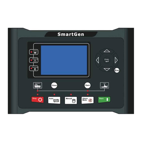
Toyama SmartGen HGM400N Series User manual

PLEASE READ THIS MANUAL CAREFULLY. IT CONTAINS INFORMATION FOR YOUR SAFETY.
POR FAVOR, LEA ATENTAMENTE ESTE MANUAL. CONTIENE INFORMACIÓN PARA SU SEGURIDAD.
POR FAVOR, LEIA ATENTAMENTE ESTE MANUAL. ELE CONTÉM INFORMAÇÕES PARA SUA SEGURANÇA.
OWNER’S MANUAL
GUÍA DEL PROPIETARIO • MANUAL DO PROPRIETÁRIO
Controller Manual
Manual del Controlador •manual do controlador


English
PERFORMANCE AND CHARACTERISTICS _______________________________04
SPECIFICATION ______________________________________________04
OPERATION ________________________________________________05
PUSHBUTTONS ______________________________________________05
NDICATOR LIGHT _____________________________________________06
DEFINITION AND RANGE OF PARAMETERS_______________________________07
PARAMETERS SETTINGS _________________________________________12
TYPICAL APPLICATION __________________________________________13
OVERALL DIMENSION AND PANEL CUTOUT ______________________________14
Español
RENDIMIENTO Y CARACTERÍSTICAS __________________________________16
ESPECIFICACIONES ____________________________________________16
FUNCIONAMIENTO_____________________________________________17
Botones ___________________________________________________17
INDICADORES _______________________________________________18
DEFINICIÓN Y RANGO DE PARÁMETROS ________________________________19
CONFIGURACIÓN DE PARÁMETROS __________________________________25
TYPICAL APPLICATION __________________________________________26
DIMENSIÓN GENERAL Y CORTE DEL PANEL ______________________________28
Português
DESEMPENHO E CARACTERISTICAS __________________________________30
ESPECIFICAÇÕES _____________________________________________30
OPERAÇÃO_________________________________________________31
BOTÕES __________________________________________________31
INDICADORES _______________________________________________32
DEFINIÇÃO E FAIXA DE PARAMETROS _________________________________33
CONFIGURAÇÃO DE PARAMETROS ___________________________________39
APLICAÇÃO TIPICA ____________________________________________40
DIMENSÃO GERAL E CORTE DO PAINEL ________________________________42
INDEX / INDICE / SUMÁRIO

HGM410N/HGM420N GENSET
CONTROLLER USER MANUAL
4
HGM400N series controller has two types:
HGM410N: ASM (Automatic Start Module), it controls generator to start/stop by remote signal;
HGM420N: AMF (Auto Mains Failure), updates based on HGM410N, moreover, has mains electric quantity monitoring and mains/genera-
tor automatic transfer control function, especially for automatic system composed by generator and mains.
Items Contents
Working Voltage DC8. 0V to 35. 0V, Continuous Power Supply.
Overall Consumption <3W(Standby mode: ≤2W)
AC voltage Input:
3 Phase 4 Wire
3 Phase 3 Wire
Single phase 2 Wire
2 Phase 3 Wire
AC15V - AC360V (ph-N)
AC30V - AC620V (ph-ph)
AC15V - AC360V (ph-N)
AC15V - AC360V (ph-N)
Alternator Frequency 50Hz/60 Hz
Speed Sensor Voltage 1.0V to 24V (RMS)
Speed Sensor Frequency 10,000 Hz (max)
Start Relay Output 5A DC28V power supply
Auxiliary Relay Output 1 5A DC28V power supply
Auxiliary Relay Output 2 5A DC28V power supply
Auxiliary Relay Output 3 5A DC28V power supply
Auxiliary Relay Output 4 5A AC250V voltage-free output
Auxiliary Relay Output 5 5A AC250V voltage-free output
Overall Dimensions 126mm x 109mm x 44mm
Panel Cutout 110mm x 90mm
CT Secondary Current 5A (rated)
Working Condition Temperature: (-25~70)ºC;
Humidity: (20~90)%RH
Storage Condition Temperature: (-30~+80)ºC
Protection Level IP55 Gasket
Insulation Intensity Object: among input/output/power supply
Quoted standard: IEC688-1992
Test method: AC2.2kV/1min Ileak≤3mA
Weight 0.26kg
2. SPECIFICATION
1. PERFORMANCE AND CHARACTERISTICS

HGM410N/HGM420N GENSET
CONTROLLER USER MANUAL
5
3. OPERATION
3.1 PUSHBUTTONS
Stop/ Reset
Stop running generator in Auto/Manual mode;
In case of alarm condition, pressing the button will reset alarm;
In stop mode, pressing and holding the button for 3 seconds will
test indicator lights (lamp test);
During stopping process, press this button again to stop generator
immediately.
Start Start genset in Manual/Test mode. When press this key in starting
process, genset will skip to next status.
Manual Pressing this key will set the module into manual mode.
Auto Pressing this key will set the module into auto mode.
Close/Open
For close/open switch. Pressing this key can switch between
close/open interface and homepage. At close/open interface in
manual mode, pressing up/down keys can control open or close.
Set/ Conrm
Pressing this key will enter into Main Menu;
In setting parameter status, press this key will shift cursor or con-
rm setting value.
Up/Increase
Scrolls the screen up; shift the cursor up or increase the set value
in parameter setting menu.
When at close/open interface in manual mode:
Pressing this key can control mains close/open (HGM420N) and
gen close (HGM410N).
Down/Decrease
Scrolls the screen down; shift the cursor down or decrease the set
value in parameter setting menu.
When in close/open interface in manual mode:
Pressing this key can control mains close/open (HGM420N) and
gen close (HGM410N).

HGM410N/HGM420N GENSET
CONTROLLER USER MANUAL
6
Note:Note: Partial indicator states
Alarm Lamp: slowly blink when warning alarms; fast blink when shutdown alarms; won’t illuminate when there is no alarm.
Status Lamp: won’t illuminate when genset stand by; blink 1 time in start or stop process and always illuminate when runs normally.
3.2 INDICATOR LIGHT

HGM410N/HGM420N GENSET
CONTROLLER USER MANUAL
7
4.DEFINITION AND RANGE OF PARAMETERS
No. Items Range Default Description
1 Mains Normal Delay (0-3600)s 10 The time from mains abnormal to normal or
from normal to abnormal; suitable for ATS (auto-
matic transfer switch).
2Mains Abnormal
Delay (0-3600)s 5
3 Mains Under Volt (30-620)V 184
When mains voltage has fallen below the set value,
Mains Under Voltage is active. When set the value
as 30V, the controller does not detect under volta-
ge signal. Back lash: 10V
4 Mains Over Volt (30-620)V 276
When mains voltage has exceeded the set value,
Mains Over Voltage is active. When set the value
as 620V, the controller does not detect over volta-
ge signal. Back lash: 10V
5 Transfer Rest Delay (0-99.9)s 1.0
Interval time from mains switch o to generator
switch on; or from generator switch o to mains
switch on.
6 Start Delay (0-3600)s 1 Time from mains abnormal or remote start signal
is active to start genset.
7 Stop Delay (0-3600)s 1 Time from mains normal or remote start signal is
deactivated to genset stop.
8 Start Attempts (1-10)times 3
Maximum crank times of crank attempts. When
reach this number, controller will send start failure
signal.
9 Preheat Time (0-300)s 0 Power-on time of heater plug before starter is
powered up.
10 Cranking Time (3-60)s 8 Power-on time of starter
11 Crank Rest Time (3-60)s 10 The waiting time before second power up when
engine start fail.
12 Safety On Delay (1-60)s 10
Alarms for low oil pressure, high temperature,
under speed, under frequency/voltage, charge alt
failure are inactive.
13 Start Idle Time (0-3600)s 0 Idle running time of genset when starting.
14 Warming Up Time (0-3600)s 10 Warming time between genset switch on and high
speed running.
15 Cooling Time (3-3600)s 10 Radiating time before genset stop, after it unloads.
16 Stop Idle (0-3600)s 0 Idle running time when genset stop.
17 ETS Solenoid Hold (0-120)s 20 Stop electromagnet’s power on time when genset
is stopping.
18 Fail to Stop Delay (0-120)s 0
Time between ending of genset idle delay and
stopped when “ETS time” is set as 0;
Time between ending of ETS hold delay and
stopped when “ETS time” is not 0.
19 Breaker Close Time (0-10)s 5.0 Pulse width of mains/generator switch on. When it
is 0, means output constantly.
20 Flywheel Teeth (10-300) 118
Tooth number of the engine, for judging of starter
crank disconnect conditions and inspecting of
engine speed. See the installation instructions.
21 Gen Abnormal Delay (0-20.0)s 10.0 The alarm delay of generator over voltage and
under voltage.
22 Gen Over Volt (30-620)V 276
When generator voltage has exceeded the set
value and the “Gen abnormal delay” has expired,
Gen Over Voltage is active. When set the value as
620V, the controller does not detect over voltage
signal.

HGM410N/HGM420N GENSET
CONTROLLER USER MANUAL
8
23 Gen Under Volt (30-620)V 184
When generator voltage has fallen below the set
value and the “Gen abnormal delay” has expired,
Gen Under Voltage is active. When set the value as
30V, the controller does not detect under voltage
signal.
24 Under Speed (0-6000)r/min 1200
When engine speed has fallen below the set value
for 10s, Under Speed is active. It will initiate a shut-
down alarm signal.
25 Over Speed (0-6000)r/min 1710
When engine speed has exceeded the set value for
2s, Over Speed is active. It will initiate a shutdown
alarm signal.
26 Under Freq (0-75.0)Hz 40.0
When generator frequency has fallen below the set
value but Not equal to 0 for 10s, Under Frequency
is active. It will initiate a shutdown alarm signal.
27 Over Freq (0-75.0)Hz 57.0
When generator frequency has exceeded the set
value for 2s, Over Frequency is active. It will initia-
te a shutdown alarm signal.
28 High Temp. (80-140)ºC 98
When the temperature value of the external
temperature sensor exceeds the set value, “High
Temperature” timer is initiated. Detecting only after
safety on delay has expired. If the set value is 140,
high temperature signal will not be sent (this only
concerns external temperature sensor, not high
temperature signal via cong. input port).
29 Low OP (0-400)kPa 103
When the external pressure sensor value falls
below this set value, “Low Oil Pressure” timer is
initiated. Detecting only after safety on delay has
expired. If the set value is 0, low oil pressure signal
will not be sent (this only concerns pressure sen-
sor and does not concern low oil pressure warning
signal via congurable input port)
30 Low Fuel Level (0-100)% 10
When the liquid level of the external sensor falls
below the set value, “Low Fuel Level” timer is
initiated. (this only concerns fuel level sensor and
does not concern low fuel level warning signal via
congurable input port)
31 Aux. Sensor (80-140)ºC (0-400)kPa
(0-100)% 98
Each value correspond to above 28 (Temperature
sensor), 29 (Oil pressure sensor) and 30 (Level
sensor), respectively.
32 Loss of Speed Signal (0-20.0)s 5.0 If the set value is 0, only warning and not to shut-
down the generator.
33 Charge Alt Failure (0-30)V 6.0
During generator is normal running, when alterna-
tor D+(WL) voltage has fallen below the set value
and remains for 5s, It will initiate a shutdown alarm
signal.
34 Battery Over Volt (12-40)V 33.0
When battery voltage has exceeds the set value
and remains for 20s, It will initiate a warning alarm
signal. Only warning and not to shutdown the
generator.
35 Battery Under Volt (4-30)V 8.0
When battery voltage has fallen below the set
value and remains for 20s, It will initiate a warning
alarm signal. Only warning and not to shutdown
the generator.
36 Current Trans. (5-6000)/5 500 The ratio of external CT
37 Full Load Current
Rating (5-6000)A 500 Generator’s rated current, used for load over cur-
rent calculating.
38 Over Current Percen-
tage (50-130)% 120 When the load current has exceeded the set value,
“over current” delay is initiated.

HGM410N/HGM420N GENSET
CONTROLLER USER MANUAL
9
39 Over Current Delay (0-3600)s 30
When load current has exceeded the set value and
the “over current” delay has expired, over current
alarm is initiated. When the set value is 0, only
warning and not to shutdown the generator.
40 Fuel Pump On (0-100)% 25 When fuel level has fallen below the set value for
10s, “Fuel Pump On” alarm is initiated.
41 Fuel Pump O (0-100)% 80 When fuel level has exceeded the set value for 10s,
“Fuel Pump O” alarm is initiated.
42 Aux. Output 1 (0-17) 14 Factory default: Fuel Relay Output
43 Aux. Output 2 (0-17) 2 Factory default: Energized To Stop
43 Aux. Output 3 (0-17) 5 Factory default: Gens closed
44 Aux. Output 3 (0-17) 3 Factory default: Idle Control
45 Aux. Output 4 (0-17) 5 Factory default: Close Generator
46 Aux. Output 5 (0-17) 6 Factory default: Mains Closed
47 Digital Input 1 (0-15) 1 Factory default: High Temperature Input
48 Digital Input 1 Active (0-1) 0 Factory default: Close to active
49 Digital Input 1 Delay (0-20.0)s 2.0
50 Digital Input 2 (0-15) 2 Factory default: Low Oil Pressure Warning Input
51 Digital Input 2 Active (0-1) 0 Factory default: Close to active
52 Digital Input 2 Delay (0-20.0)s 2.0 Factory default: close
53 Digital Input 3 (0-15) 10 Factory default: Remote Start
54 Digital Input 3 Active (0-1) 0 Factory default: Close to active
55 Digital Input 3 Delay (0-20.0)s 2.0 Factory default: close
56 Digital Input 4 (0-15) 11 Factory default: Fuel Level Warn
57 Digital Input 4 Active (0-1) 0 Factory default: Close to active
58 Digital Input 4 Delay (0-20.0)s 2.0 Factory default: close
59 Power On Mode (0-2) 0 0: Stop Mode 1: Manual Mode 2: Auto Mode
60 Module Address (1-254) 1 Communication address of controller.
61 Passwords (0-9999) 0318
62 Crank Disconnect (0-6) 2
There are 3 conditions of disconnecting starter
with engine: Generator Frequency, Magnetic
Pickup, Oil Pressure. Each condition can be used
alone and simultaneously to separating the start
motor and genset as soon as possible. See 7.5
63 Disconnect Magnetic
Pickup (0-3000)r/min 360 When engine speed higher than the set value, star-
ter will be disconnected.
63 Disconnect Magnetic
Pickup (0-3000)r/min 360 When engine speed higher than the set value, star-
ter will be disconnected.
64 Disconnect Gen Freq (10.0-30.0)Hz 14.0 When generator frequency higher than the set
va-lue, starter will be disconnected.
65 Disconnect OP (0-400)kPa 200 When generator oil pressure higher than the set
value, starter will be disconnected.
66 High Temp. Inhibit
Enabled (0-1) 0 Factory default: when high temperature occurs,
shutdown alarm is initiated. Note 2
67 Low OP Inhibit Ena-
-bled (0-1) 0 Factory default: when low oil pressure occurs,
shu-tdown alarm is initiated. Note 3
68 Low Fuel Level
Inhibit (0-1) 1 Factory default: when low fuel level occurs, shu-t-
down alarm is initiated. Note 4
69 Cong. Sensor
Inhibit (0-1) 1
Factory default: when cong. sensor value higher/
lower than the set value (particular case depends
on the sensor type), shutdown alarm is initiated.
70 AC System (0-3) 0 0: 3P4W; 1: 2P3W 2: 1P2W; 3: 3P3W
71 Temp. Sensor Curve (0-12) 8 SGX See 7.4

HGM410N/HGM420N GENSET
CONTROLLER USER MANUAL
10
72 Pressure Sensor
Curve (0-12) 8 SGX See 7.4
73 Multiplex Input 1 (0-1) 0 0: Digital Input 3
1: Level Sensor
74 Level Sensor Curve (0-7) 3 SGD See 7.4
75 Multiplex Input 2 (0-3) 0 0: Digital Input 4 1: Temperature Sensor 2: Oil
Pressure Sensor 3: Level Sensor Note 5
76 Cong. Sensor Curve (0-9) (0-9) (0-5) 8 8 3 SGX SGX SGD
77 Poles (2-64) 4
0:Dened temperature sensor
1: Dened pressure sensor
2: Dened liquid level sensor
Select the sensor, input corresponding 8 values.
78 Temp. Sensor Open (0-2) 1 0:Indication; 1:Warn; 2:Shutdown (temperature
sensor will show “+++”);
79 OP Sensor Open (0-2) 1 0: Indication (oil pressure sensor will show “+++”);
1:Warn; 2:Shutdown
80 Fuel Level Sen-sor
Open (0-2) 1 0: Indication (fuel level sensor will show “+++”);
1:Warn; 2:Shutdown
81 Cong. Sensor Open (0-2) 1 0: Indication (LCD display will show “+++”);
1:Warn; 2:Shutdown
82 Cooling Blower On (0-140)ºC 60 It controls the cooling blower to open or close if
the output port is congured as Cooling Blower.
83 Cooling Blower O (0-140)ºC 40
84 Low Fuel Level Warn (0-100)% 20
When the liquid level of the exter-nal sensor falls
below the set value, “Low Fuel Level” timer is
initiated. (this only concerns fuel level sensor and
does not concern low fuel level warning signal via
congurable input port)
85 Gen Over Volt Warn (30-620)V 253
When genset voltage is over the point, genera-tor
over voltage is active. When the point is 620V,
generator over voltage is disa-bled.
86 Gen Under Volt (30-620)V 193
When generator voltage is under the point, genera-
-tor under voltage is active. When the point is 30V,
generator under voltage is disabled.
87 Gen Over Freq Warn (0-75.0)Hz 55.0 When generator’s frequency is over the point,
genera-tor over frequen-cy is active.
88 Gen Under Freq
Warn (0-75.0)Hz 42.0 When generator frequency is lo-wer than the point,
warn alarm signal will be sent.
89 Gen Over Current
Warn (50-130)% 110
When load cur-rent is over the point, over current
is active. When this value is 0, warn alarm signal
won’t be sent.
90 High Temp. Warn (80-140)ºC 95
When the tempe-rature value of the external
tem-perature sensor exceeds the set value, “High
Temperature” timer is initiated. Detecting only after
safety on delay has expired. If the set value is 140,
high tempe-rature signal will not be sent (this only
concerns external tempera-ture sensor, not high
temperature signal via cong. input port).
91 Low OP Warn (0-400)kPa 124
When the exter-nal pressure sen-sor value falls
below this set value, “Low Oil Pressure” timer
is initiated. Detec-ting only after safety on delay
has expired. If the set value is 0, low oil pressure
signal will not be sent (this only con-cerns pressu-
re sensor and does not concern low oil pressure
war-ning signal via congurable input port)
92 Aux. Sensor Warn (80-140)ºC (0-400)kPa
(0-100)% 95
Respective cor-responding with 90 temp. sensor,
91 pressure sen-sor and 84 level sensor in this
table.

HGM410N/HGM420N GENSET
CONTROLLER USER MANUAL
11
93 Gen Over Volt Delay (0-20.0)s 10.0
When generate voltage exceeds shutdown value
and last for a whi-le, gen over volt shutdown is
acti-ve.
94 Gen Over Freq Delay (0-20.0)s 2.0
When generate frequence ex-ceeds shutdown
value and last for a while, gen over freq shutdown
is active.
95 Disconnect OP Delay (0-20.0)s 0.0s
When disconnect conditions include oil pressure
and engine oil pressu-re is higher than disconnect
oil pressure delay, the genset is re-garded as start
successfully and starter will dis-connect.
96 Timing Start (0-1) (0-1) 0 0 0: Disabled; 1:Enabled 0:No-load; 1:On-load
97 Timing Start Cir-cu-
late
(0-2) (
1-31)
(0-7)
(1-23)h
(1-59)min
(0-30000)min
0
1
0
0
0
30
0: monthly; 1: weekly; 2:daily
Day(0:monthly is active)
Week(0:weekly is active)
Prohibit start time (h)
Prohibit start time (min)
Duration
98 Auto Start Inhibi-ted (0-1) 0 0: Disabled; 1:Enabled
99 Auto Start Circula-te
Inhibited
(0-2)
(1-31)
(0-7)
(1-23)h
(1-59)min
(0-30000)min
0
1
0
0
0
30
0: monthly; 1: weekly; 2:daily
Day(0:monthly is active)
Week(0:weekly is active)
Prohibit start time (h)
Prohibit start time (min)
Duration
100 Over Power
(0-2)
(0-6000)kW
(0-6000)kW
(0-3600)s
0
304
290
5
0 Inactive; 1 Warn; 2 Alarm Shutdown
Over power setting value
Over power warn return
Over power delay
When power is higher than preset value and du-
ration exceeds than delay, over power warning is
active. Return and delay value can be set.
101 Date Set the date of controller.
102 Custom Sensor
Curve (0-3) 0
0 Custom temperature sensor
1 Custom pressure sensor
2 Custom level sensor
3 Custom auxiliary sensor
Choose sensor which need to be set, input every
point(8 points need to be input) resistance and
corresponding value(or current, voltage) of curve.
Note1:Note1: The default value in “No.” column is for HGM420N and the number value needs to minus 5 for HGM410N.
Note2:Note2: If “high temperature inhibit” is congured, or set auxiliary input as “inhibit high temperature stop” and this input is active, when
temperature is higher than the preset value, or high temperature alarm input is active, controller will send warning signal only and not
stop the unit.
Note3:Note3: If “low oil pressure inhibit” is congured, or set auxiliary input as “inhibit low oil pressure stop” and this input is active, when
oil pressure is lower than the preset value, or low oil pressure alarm input is active, controller will send warning signal only and not stop
the unit.
Note4:Note4: If “low fuel level inhibit” is congured, or set auxiliary input as “inhibit low fuel level stop” and this input is active, when fuel
level is lower than the preset value, or low fuel level alarm input is active, controller will send warning signal only and not stop the unit.
Note5:Note5: Multiplex Input can be set as “auxiliary input” or “level sensor”; if one of them is set successfully, then the corresponding items
are active. For instance, if set “Multiplex Input 3” as “Auxiliary Input”, the related conguration items of auxiliary input 3 are active; if set
“Multiplex Input 3” as “Level Sensor”, the related conguration items of level sensor are active;
Note6:Note6: If default password (0318) isn’t changed, it doesn’t need to input when conguring parameters via PC software; if the password
is changed for the rst time via PC software, it need to input password in password window.
Note7:Note7: Between input correct password and LCD back light haven’t got dark, input parameter numbers can enter parameter setting
interface when enters “Password Input” again.
Note8:Note8: In teeth conguration interface, congure teeth status and power large than 20Hz, press start key for auto calculating teeth
numbers and press conrm key for changing teeth numbers.

HGM410N/HGM420N GENSET
CONTROLLER USER MANUAL
12
5.PARAMETERS SETTINGS
Start the controller, then press to enter into the parameters setting menu as below:
1. Set Parameters
2. Information
3. Language
4. Event Log
5. Maintenance Setting
a)Parameters Settinga)Parameters Setting
“0318” can set all items in parameters during inputting password. When default password has been changed, it
needs to input the same password with controller for parameter setting via PC software. If more parameter items
need to be set or password is forgotten, such as voltage and current calibration, please contact with the factory.
b)Informationb)Information
LCD will display some information of controller, such as software version, hardware version, issue date.
Note1:Note1:
1)HGM410N, there are not items 1-5 in parameters; programmable output 1-4 have no digital outputs about mains.
2)Please modify the parameters in standby mode (crank conditions, auxiliary input and output conguration, multi delays, etc.)
otherwise shutdown alarm or other abnormal conditions may appear.
3)The over-voltage threshold must be greater than the under-voltage threshold; otherwise over-voltage and under-voltage will
occur at the same time.
4)The over-speed threshold must be greater than under-speed threshold, otherwise over speed and under speed will occur at
the same time.
5)Set frequency value (after crank disconnect) as low as possible, in order to disconnect starter quickly.
6)Programmable input 1-4 cannot be set as the same items, otherwise it cannot realize correct function; programmable output
1-5 can be set as the same item.
7)Digital input 3 can be congured as Fuel Level Sensor. Digital input 4 can be congured as Temperature Sensor, Oil Pressure
Sensor and Water Level Sensor. Digital input and sensor need to be picked one: if input is chosen, the corresponding digital input
parameter is active and the sensor parameter inactive but saved; otherwise if sensor is chosen, the corresponding sensor para-
meter is active and the digital input parameter is inactive but saved.
8)If need to shut down after cooling, please set any input as “ stop after cooling “, then connect this input to ground; or set high
temperature stop action as “cooling stop”
Note:Note: Pressing will display the status of digital inputs and outputs.
c)LCD contractc)LCD contract
Press and (or and ) can adjust LCD contract. Adjustment range is 0-7.
d)Languaged)Language
User may select display language as Chinese, English, Spanish, Russian, Turkey and French.
e)Event Loge)Event Log
Users can check event log (max. 99) on this interface including start/stop info and shutdown alarms.
f)Maintenance Settingf)Maintenance Setting
The default password (when enter maintenance setting) is 0 (it needs to contact sales or after sale personnel to
change the password). It’ll refresh maintenance time after entered maintenance setting.

HGM410N/HGM420N GENSET
CONTROLLER USER MANUAL
13
6. TYPICAL APPLICATION

HGM410N/HGM420N GENSET
CONTROLLER USER MANUAL
14
Suggestion:Suggestion: Expand relay with high capacity in start and fuel output is recommend.
6.1 OVERALL DIMENSION AND PANEL CUTOUT
1) Battery Voltage Input1) Battery Voltage Input
HGM400N series controller can suit for widely range of battery voltage DC(8~35)V. Negative of battery must be
connected with the engine shell. The diameter of wire from power supply to battery must be over 2.5mm2. If oating
charge congured, please rstly connect output wires of charger to battery’s positive and negative directly, then,
connect wires from battery’s positive and negative to controller’s positive and negative input ports in order to pre-
vent charge disturbing the controller’s normal working.

HGM410N/HGM420N GENSET
CONTROLLER USER MANUAL
15
2) Speed Sensor Input2) Speed Sensor Input
Speed sensor is the magnetic equipment which be installed in starter and for detecting ywheel teeth. Its connec-
tion wires to controller should apply for 2 cores shielding line. The shielding layer should connect to No. 1 terminal
in controller while another side is hanging in air. The else two signal wires are connected to No.1 and No.17 termi-
nals in controller. The output voltage of speed sensor should be within AC(1~24)V (eective value) during the full
speed. AC12V is recommended (in rated speed). When install the speed sensor, let the sensor is spun to contacting
ywheel rst, then, port out 1/3 lap, and lock the nuts of sensor at last.
3) Output And Expansion Relay3) Output And Expansion Relay
All outputs of controller are relay contact output type. If need to expand the relays, please add freewheel diode to
both ends of expand relay’s coils (when coils of relay has DC current) or, add resistance-capacitance return circuit
(when coils of relay has AC current), in order to prevent disturbance to controller or others equipment.
4) AC Input4) AC Input
HGM400N series controller must be connected to outside current transformer. And the current transformer’s secon-
dary side current must be 5A. At the same time, the phases of current transformer and input voltage must correct.
Otherwise, the collected current and active power maybe not correct.
Note:Note:
1. ICOM port must be connected to negative pole of battery.
2. When there is load current, transformer’s secondary side prohibit open circuit.
5) Withdraw Voltage Test5) Withdraw Voltage Test
When controller had been installed in control panel, if need the high voltage test, please disconnect controller’s all
terminal connections, in order to prevent high voltage into controller and damage it.

MANUAL DE USUARIO DEL
CONTROLADOR HGM410N/HGM420N
16
Hay dos tipos del controlador de la serie HGM400N:
HGM410N: ASM (Módulo de Arranque Automático) controla el generador para iniciar / detener por señal remota;
HGM420N: AMF (Fallo en la red eléctrica automática), actualizaciones basadas en el HGM410N, además, cuenta con monitoreo eléctrico
de la cantidad de la red eléctrica y función de control automático de la transferencia de la red eléctrica / generador, especialmente para
sistemas automáticos compuestos por generador y red eléctrica.
Items Contents
Tensión de trabajo Dc8. 0V a 35. 0V, Fuente de alimentación continúa.
Consumo general <3W (en espera: ≤2W)
Voltaje CA:
Entrada: 3 fases
4 Cables
3 Fases 3 Cables
monofásicos 2 Cables
2 Fase 3 Alambres
AC15V - AC360V (ph-N)
AC30V - AC620V (ph-ph)
AC15V - AC360V (ph-N)
AC15V - AC360V (ph-N)
Frecuencia del alternador 50Hz/60 Hz
Tensión del sensor de velocidad 1.0V a 24V (RMS)
Frecuencia del sensor de velocidad 10.000 Hz (máx.)
Iniciar salida de relé Fuente de alimentación 5A DC28V
Salida de relé auxiliar 1 Fuente de alimentación 5A DC28V
Salida de relé auxiliar 2 Fuente de alimentación 5A DC28V
Salida de relé auxiliar 3 Fuente de alimentación 5A DC28V
Salida de relé auxiliar 4 Salida sin tensión de 5A AC250V
Salida de relé auxiliar 5 Salida sin tensión de 5A AC250V
Dimensión total 126mm x 109mm x 44mm
Recorte de paneles 110mm x 90mm
Corriente secundaria de CT 5A (clasicado)
Condiciones de trabajo Temperatura: (-25 ~ 70) oC; Humedad: (20 ~ 90) % RH
Estado de almacenamiento Temperatura: (-30 ~ +80) oC
Nivel de protección IP55
Intensidad del aislamiento Objeto: entre entrada / salida / fuente de alimentación Estándar citado:
IEC688-1992
Peso 0.26kg
2. ESPECIFICACIONES
1. RENDIMIENTO Y CARACTERÍSTICAS

MANUAL DE USUARIO DEL
CONTROLADOR HGM410N/HGM420N
17
3. FUNCIONAMIENTO
3.1 BOTONES
Parar / Reiniciar
En modo Automático/Manual Detiene el generador;
En caso de condición de alarma, al pulsar el botón se restablecerá
la alarma;
En el modo de parada, al mantener pulsado el botón durante 3 se-
gundos se probarán las luces indicadoras (prueba de la lámpara);
Durante el proceso de parada, pulse este botón de nuevo para
detener el generador inmediatamente
Encender
Inicie el grupo electrógeno en el modo Manual /Test. Al pulsar
esta tecla al principio del proceso, el grupo electrógeno pasará al
siguiente estado.
Manual Al pulsar esta tecla, el módulo estará en modo manual.
Automático Pulsando esta tecla pondrá el módulo en modo automático.
Cerrar / Abrir
Para el interruptor cerrar / abrir. Al pulsar esta tecla se puede
cambiar entre la interfaz de cerrar / abrir y la página de inicio. En
la interfaz de cerrar / abrir en modo manual, al presionar las teclas
arriba/abajo se puede controlar la apertura o el cierre.
Denir / Conrmar
Pulsando esta tecla entrará en el menú principal;
Al establecer el estado del parámetro, pulse esta tecla para cam-
biar el cursor o conrmar el valor de la conguración.
Arriba / Aumentar
Mueva la pantalla hacia arriba; mueva el cursor hacia arriba o
aumente el valor establecido en el menú de conguración de pará-
metros.
Cuando en la interfaz cerrar / abrir en modo manual:
Al pulsar esta tecla se puede controlar el cerrar / abrir de la red
(HGM420N) y el bloqueo general (HGM410N).
Abajo / Disminuir
Mueve la pantalla hacia abajo; desplácese hacia abajo o disminuya
el valor establecido en el menú de conguración de parámetros.
Cuando esté en la interfaz de cerrar / abrir en modo manual:
Al pulsar esta tecla se puede controlar el cerrar / abrir de la red
(HGM420N) y el bloqueo general (HGM410N).

MANUAL DE USUARIO DEL
CONTROLADOR HGM410N/HGM420N
18
Nota:Nota: Indicadores parciales
Lámpara de alarma: parpadea lentamente al alertar a las alarmas; parpadea rápidamente cuando la alarma está apagada; no se encende-
rá cuando no haya alarma.
Lámpara de estado: no se encenderá cuando el grupo electrógeno esté en espera; 1 vez en el proceso de inicio o parada y siempre en-
cender cuando se ejecuta normalmente.
3.2 INDICADORES
Arriba
Arriba
Abajo
Abajo
Auto
Auto
Luz de alerta Auto
Luz de alerta Auto
Cierre de Red
Red Normal
Luz del Estado
Luz del Estado
Luz del Alarma
Luz del Alarma
Luz de alerta Paro
Luz de alerta Paro
Paro
Paro
Denir / Conrmar
Denir / Conrmar
Gen Cerrado
Gen Cerrado
Gen Normal
Gen Normal
Encender
Encender
Manual
Manual
Abrir / Cerrar
Abrir / Cerrar
Luz de alerta
Manual
Luz de alerta Abrir / Cerrar
Luz alerta
Manual
Luz alerta Abrir / Cerrar

MANUAL DE USUARIO DEL
CONTROLADOR HGM410N/HGM420N
19
4. DEFINICIÓN Y RANGO DE PARÁMETROS
No. Artículos Variación Predeter-
minado Descripción
1Retraso normal de
la red (0-3600)s 10 El tiempo de la red eléctrica es anormal o normal o
de normal a anormal; adecuado para ATS (Sistema
de Transferencia Automática).
2Retraso anormal de
la red (0-3600)s 5
3 Sobretensión de red (30-620) V 184
Cuando el voltaje de la red cae por debajo del
valor establecido, la red eléctrica bajo voltaje está
activa. Cuando se establece en 30V, el controlador
no detecta señales de baja tensión. Látigo trasero:
10V
4 Sobretensión de red (30-620) V 276
Cuando el voltaje de la red supera el valor esta-
blecido, la sobretensión de la red eléctrica está
activa. Al establecer el valor en 620V, el controla-
dor no detecta, señales de sobretensión. Látigo
trasero: 10V
5Retraso de transfe-
rencia (0-99.9)s 1.0
Tiempo de intervalo entre la red eléctrica y el gene-
rador; o del generador desconectado hasta la red
eléctrica.
6 Retraso en el inicio (0-3600)s 1
El tiempo de la red eléctrica, señal de arranque
anormal o remota, está activo para iniciar el grupo
electrógeno.
7 Retraso para detener (0-3600)s 1
El tiempo de la señal del arranque normal o remota
es desactivado para la parada del grupo electróge-
no.
8 Inicio de los intentos (1-10) veces 3
Veces máximas de intentos de arranque. Cuando
alcanza este número, el controlador envía una
señal de falla de inicio.
9Tiempo de precalen-
tamiento (0-300)s 0 Tiempo de arranque del calentador antes de la
salida.
10 Tiempo de arranque (3-60)s 8 Tiempo de inicio del arrancador.
11 Tiempo de descanso (3-60)s 10 El tiempo de espera antes del segundo arranque
cuando la primera falla.
12 Seguridad en el
retraso (1-60)s 10
Las alarmas para baja presión de aceite, alta tem-
peratura, baja velocidad, baja frecuencia / voltaje,
falla del alternador de carga están inactivas.
13 Tiempo de marcha
lenta (0-3600)s 0 Tiempo de inactividad de funcionamiento del gru-
po electrógeno al arrancar.
14 Tiempo de calenta-
miento (0-3600)s 10 Tiempo de calentamiento entre el grupo electróge-
no encendido y arranque a alta velocidad.
15 Tiempo de enfria-
miento (3-3600)s 10 Tiempo de enfriamiento antes de que el grupo
electrógeno se detenga, después de descargar.
16 Parada de marcha
lenta (0-3600)s 0 Tiempo de inactividad cuando se detiene el grupo
electrógeno.
17 Solenoide ETS (0-120)s 20 Detiene la energía del electroimán en el momento
en que el grupo electrógeno se esté deteniendo.
18 Fallo al detener el
retraso (0-120)s 0
El tiempo entre el nal del retardo de inactividad
del grupo electrógeno se cronometra cuando el
"tiempo ETS" se establece en 0;
El tiempo entre el nal de ETS conserva el retardo
y para cuando el "tiempo ETS" no es 0.
19 Tiempo de cerra-
miento del disyuntor (0-10)s 5.0
Anchura del pulso de la red eléctrica/generador
conectado. Cuando es 0, signica salida constan-
temente.

MANUAL DE USUARIO DEL
CONTROLADOR HGM410N/HGM420N
20
20 Dientes del volante (10-300) 118
Número de diente del motor, para evaluar las con-
diciones de desconexión de arranque e inspeccio-
nar la velocidad del motor. Consulte las instruccio-
nes de instalación.
21 Retraso anormal del
generador (0-20.0)s 10.0 El retraso de la alarma de sobretensión y la sub-
tensión del generador.
22 Alta voltaje del gene-
rador (30-620) V 276
Cuando el voltaje del generador supera el valor
establecido y expira el "retardo anormal de gene-
ración", la sobretensión de generación está activa.
Al establecer el valor en 620V, el controlador no
detecta señal de sobretensión.
23 Bajo voltaje del ge-
nerador (30-620) V 184
Cuan do el voltaje del generador cae por debajo
del valor establecido y expira el "Retraso anormal
del generador", la subtensión del generador está
activa. Al ajustar el valor a 30V, el controlador no
detecta la señal de bajo voltaje.
24 Baja velocidad (0-6000)r/min 1200
Cuando la velocidad del motor cae por debajo del
conjunto durante 10s, la baja velocidad está activa.
Iniciará una señal de alarma de apagado.
25 Alta velocidad (0-6000)r/min 1710
Cuando la velocidad del motor supera el valor es-
tablecido en 2s, la velocidad excesiva está activa.
Iniciará una señal de alarma de apagado.
26 Baja frecuencia (0-75.0) Hz 40.0
Cuando la frecuencia del generador cae por debajo
del valor establecido, pero no es igual a 0 para
10s, la opción De sub frecuencia está activa. Inicia-
rá una señal de alarma de apagado
27 Alta frecuencia (0-75.0) Hz 57.0
Cuando la frecuencia del generador supera el valor
establecido por 2s, la frecuencia excesiva está
activa. Iniciará una señal de alarma de apagado.
28 Alta temperatura. (80-140)oC 98
Cuando el valor de temperatura del sensor exter-
no de temperatura supera el valor establecido, se
inicia el temporizador "Alta temperatura". Detec-
tando solo después de que expire la seguridad del
retardo. Si el valor ajustado es 140, no se enviará
la señal de alta temperatura (esto sólo se reere
al sensor de temperatura externo, no a la señal de
alta temperatura a través de la puerta de entrada
de conguración).
29 Baja presión de
aceite (0-400)kPa 103
Cuando el valor del sensor de presión externo
cae por debajo del valor establecido, se inicia el
temporizador "Baja presión de aceite". Detectando
solo después de que expire la seguridad del retar-
do. Si el valor ajustado es 0, no se enviará la señal
de baja presión de aceite (esto sólo se reere al
sensor de presión y no a la señal de advertencia
de baja presión de aceite a través del puerto de
entrada congurable)
30 Bajo nivel de com-
bustible (0-100)% 10
Cuando el nivel de líquido del sensor externo
cae por debajo del valor establecido, se inicia el
temporizador "Low Fuel Level". (esto se reere
únicamente al sensor de nivel de combustible y
no a la señal de advertencia de bajo combustible a
través del puerto de entrada congurable).
31 Sensor auxiliar
(80-140)°C
(0-400)kPa
(0-100)%
98
Cada valor corresponde a una línea de ácima 28
(sensor de temperatura), 29 (sensor de presión de
aceite) y 30 (sensor de nivel), respectivamente.
32 Señal de pérdida de
Velocidad (0-20.0)s 5.0 Si el valor ajustado es 0, solo advierte, pero no
apaga el generador.
This manual suits for next models
2
Table of contents
Languages:
Popular Controllers manuals by other brands

DSEGenset
DSEGenset DSE8610 Operator's manual

Clarke
Clarke CAT189 Operating & maintenance instructions

Aimco
Aimco AcraDyne Gen IV Operator's manual
Emerson
Emerson Alco Controls EC3 Series operating instructions

Norac
Norac UC4+ User & installation manual
McQuay
McQuay MicroTech 2000 Installation and maintenance manual
