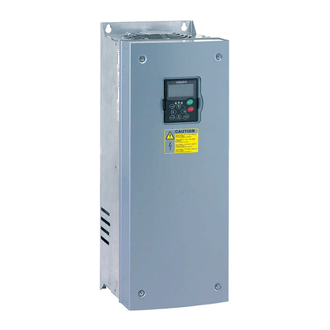
TOYODenki VF66 User manual

TOYO INTELLIGENT INVERTER
VF66B (DC motor drive)
Operating Manual

1
Preface
Thank you very much for choosing our product.
This manual describes how to handle a main unit of TOYO VF66B (DC motor drive). It provides instructions
for using VF66B (DC motor drive), such as how to install, wire, and operate it correctly as well as handling
methods of its protection operation. Before operating VF66B (DC motor drive), be sure to carefully read this
manual.
In addition to the standard functions, TOYO VF66B (DC motor drive) provides many other features. You can
build an optimal system for different applications by using its various functions. In such a case, preferentially
use the values described in the dedicated "Instruction Manual" and "Test Report" for the function.
When delivering any of your products with VF66B (DC motor drive) built in, consider that this manual can be
distributed to end users. Also, when changing our factory default initialized data (hereinafter referred to as
Initialized data) for setting parameters of VF66B (DC motor drive), make sure that end users can be informed
about the changed contents of the Initialized data.

2
Be Sure To Read This Before Use
Safety Notice
To use VF66B (DC motor drive) correctly, be sure to completely read this manual and all other attached
documents before installation, operation, maintenance, and inspection. You need to have a good knowledge
of equipment, safety information, and all notices before using VF66B (DC motor drive).
In this manual, safety notices are ranked as "Danger", "Warning", and "Caution".
Danger When improper use may cause a dangerous situation, death or serious injury may result,
and its danger seems to be very urgent.
Warning When improper use may cause a dangerous situation, and death or serious injury may
result.
Caution
When improper use may cause a dangerous situation, medium-level or minor injury may
result, and only physical damage may result. However, it can cause serious results
depending on the situation. Cautions described in this manual are all important. Be sure to
observe them.
Caution [Installation]
Install VF66B (DC motor drive) on non-inflammables such as metal.
Otherwise, a fire may occur.
Do not put inflammables near VF66B (DC motor drive).
Otherwise, a fire may occur.
Do not hold the front cover when transporting VF66B (DC motor drive).
It may fall, which can result in injury.
Install VF66B (DC motor drive) in a place which can support its weight.
It may fall, which can result in injury.
Do not install and operate VF66B (DC motor drive) which is damaged or does not have any parts.
Otherwise, you may be injured.
Danger [Wiring]
Check that the input power is turned off before wiring.
Otherwise, electric shock or a fire may occur.

3
Warning [Wiring]
Be sure to connect a ground wire.
Otherwise, electric shock or a fire may occur.
Electrical engineering technicians should connect wires.
Otherwise, electric shock or a fire may occur.
Be sure to install VF66B (DC motor drive) before wiring.
Otherwise, electric shock or a fire may occur.
For ground fault protection, connect the leakage guard relay or ground fault interrupter exclusive for VF66B (DC
motor drive) to the inputs (R/L1, S/L2, T/L3) of VF66B (DC motor drive).
Otherwise, electric shock or a fire may occur.
Warning [Wiring]
Do not connect the alternating-current power supply to the output terminals (P/N).
Otherwise, injury or a fire may occur.
Check that the rated voltage of the product and the voltage of the alternating-current power supply match with
each other.
Otherwise, injury or a fire may occur.
Do not directly connect a resistor between direct-current terminals 1/ 2 and or 1 and 2.
Otherwise, a fire may occur.
Warning [Operation]
Be sure to install the front cover before turning on the input power. Do not remove the front cover during
energization.
Otherwise, it can result in a risk of electric shock.
Do not use the switches with wet hands.
Otherwise, it can result in a risk of electric shock.
Do not touch the VF66B (DC motor drive) terminals while VF66B (DC motor drive) is energized, even during
stop.
Otherwise, it can result in a risk of electric shock.
Warning [Operation]
The stop button is available only when functions have been set. Provide an emergency stop button separately.
Otherwise, you may be injured.
When alarm reset is performed with operation signals input, VF66B (DC motor drive) suddenly restarts. Check
that signals are turned off, and then perform alarm reset.
Otherwise, you may be injured.
Caution [Operation]
Do not touch a heat sink and a discharge resistor because they reach high temperatures.
Otherwise, you may get burned.
You can set a wide range of operation from high speed to low speed with VF66B (DC motor drive). Before
operation, check the permitted range of the motor and machinery sufficiently.
Otherwise, you may be injured.
Provide a holding brake separately if necessary.
Otherwise, you may be injured.

4
Warning [Maintenance and inspection, and replacement of parts]
Before inspection, turn off the input power after checking that the motor is stopped, and then wait for over ten
minutes.
Also, check that direct-current voltage between 1 and or 2 and is less than or equal to 30 V.
Otherwise, electric shock, injury, or a fire may occur.
Check that the rated voltage of the product and the voltage of the alternating-current power supply match with
each other.
Otherwise, injury, electric shock, or part damage may occur.
Do not perform maintenance and inspection or replace parts except qualified persons.
Use a tool for insulation for maintenance and inspection.
Otherwise, electric shock or injury may occur.
Warning [Others]
Never modify VF66B (DC motor drive).
Otherwise, electric shock or injury may occur.
Caution [General notice]
To provide detailed explanation, all figures described in this manual are sometimes drawn with the cover or a safety
shield removed. To operate VF66B (DC motor drive), be sure to set the specified cover or shield to its original position
and to follow the procedure described in this manual.
These safety notices and specifications in this manual are subject to change without notice.

5
Contents
Be Sure To Read This Before Use.................................................................................................................. 2
Safety Notice.................................................................................................................................................. 2
Chapter 1 For Application............................................................................................................................... 7
1.1. Checking Package and Inspection on Purchase............................................................................. 7
Chapter 2 How to Connect VF66B (DC motor drive)
............................................................................................. 9
2.1. How to Connect VF66B (DC motor drive) ....................................................................................... 9
2.1.1. How to Connect VF66B (DC motor drive) Terminals................................................................ 9
2.2. Terminal/Connector Specifications ................................................................................................ 10
2.2.1. Terminal/Connector Specifications......................................................................................... 10
2.3. How to Connect the Printed Control Board [VFC66-Z] and Field Amplifier................................... 12
2.3.1. How to Connect the Printed Control Board [VFC66-Z] and Field Amplifier ........................... 12
2.4. Application of LC filter.................................................................................................................... 13
2.4.1. Role of LC Filter ..................................................................................................................... 13
2.4.2. Power Constant Operation..................................................................................................... 13
2.4.3. Selection of LC Filter .............................................................................................................. 13
2.5. PG.................................................................................................................................................. 14
2.5.1. Applicable PG......................................................................................................................... 14
2.5.2. Use of PGs Attached to the Existing Products....................................................................... 14
Chapter 3 For Operation ............................................................................................................................... 15
3.1. Overview of Operation................................................................................................................... 15
3.1.1. Power-On ............................................................................................................................... 15
3.1.2. Cooling Fan Operation ........................................................................................................... 16
3.2. Console Panel [SET66EX-Z]......................................................................................................... 16
3.2.1. Panel ...................................................................................................................................... 16
3.2.2. Operation Keys....................................................................................................................... 17
3.2.3. Overview of Operation............................................................................................................ 18
3.2.4. How to Check Monitor Information......................................................................................... 19
3.2.5. List of Monitor Items ............................................................................................................... 20
3.3. How to Perform Trial Operation..................................................................................................... 23
3.3.1. How to Change the Motor Speed........................................................................................... 24
3.3.2. How to Change the Acceleration/Deceleration time............................................................... 25
3.3.3. How to Change the Rotation Direction................................................................................... 26
3.3.4. How to Perform JOG Operation ............................................................................................. 26
Chapter 4 How to Change Parameters with Console Panel...................................................................... 27
Chapter 5 List of Setting Areas .................................................................................................................... 28
Chapter 6 List of Parameters........................................................................................................................ 29
6.1. Basic Setting Area ......................................................................................................................... 29
6.2. Area A (Maximum Speed, Rated Motor, Parameters Setting Area) .............................................. 29
6.3. Area b (Operation Sequence Setting Area)................................................................................... 31
6.4. Area c (Multifunction Input Related Setting Area) ......................................................................... 33
6.5. Area d (Acceleration/Deceleration Time Setting, Speed Jump Function, MRH Function Setting
Area).............................................................................................................................................. 34
6.6. Area E (Current Cotrol Gain, Output Voltage Limit Related Setting Area) .................................... 35
6.7. Area F (Built-in DB (Dynamic Braking) Operation, Protection Function, Traceback Setting Area)36
6.8. Area G (Analog Input/Output Setting Area) ................................................................................... 37
6.9. Area H (Multifunction Output Setting Area) ................................................................................... 39
6.10. Area i (Speed Control/Amature Current Control /Amature Voltage Control Switch Setting Area) 40
6.11. Area J (Communication Setting Area) ........................................................................................... 42
6.12. Area L (Setting Area for Analog Input and Output Gain) ............................................................... 43
6.13. Area n (VF66B (DC motor drive) Model Area) .............................................................................. 44
6.14. Area o (Special Adjustment Area) ................................................................................................. 44

6
6.15. Area P (Internal PLC Function Parameter) ................................................................................... 44
6.16. Area S (Setting Area for Mode Selection and Analog Input/Output Adjustment) .......................... 45
Chapter 7 Descriptions of Parameters ........................................................................................................ 46
7.1. Basic Setting Area ......................................................................................................................... 46
7.2. Area A (Maximum Speed, Rated Motor, Parameters Setting Area) .............................................. 47
7.3. Area b (Operation Sequence Setting Area)................................................................................... 54
7.4. Area c (Multifunction Input Related Setting Area) ......................................................................... 65
7.5. Area d (Acceleration/Deceleration Time Setting, Speed Jump Function, MRH Function Setting
Area).............................................................................................................................................. 71
7.6. Area E (Current Control Gain, Output Voltage Limit Related Setting Area) .................................. 76
7.7. Area F (Built-in DB (Dynamic Braking) Operation, Protection Function, Traceback Setting Area)80
7.8. Area G (Analog Input/Output Setting Area) ................................................................................... 85
7.9. Area H (Multifunction Output Setting Area) ................................................................................... 91
7.10. Area i (Speed Control/Amature Current Control/Amature Voltage Control Switch Setting Area) . 96
7.11. Area J (Communication Setting Area) ......................................................................................... 104
7.12. Area L (Setting Area for Analog Input and Output Gain) ............................................................. 106
7.13. Area n (VF66B (DC motor drive) Mode Area) ............................................................................. 108
7.14. Area o (Special Adjustment Area) ............................................................................................... 109
7.15. Area P (Internal PLC Function Parameter) ................................................................................. 109
7.16. Area S (Setting Area for Mode Selection and Analog Input/Output Adjustment) .........................110
Chapter 8 Troubleshooting......................................................................................................................... 124
8.1. Protection Messages and Actions ............................................................................................... 124
8.1.1. List of Protection Messages ................................................................................................. 124
8.1.2. Protection Messages and Actions ........................................................................................ 130
8.1.3. What Are Displayed in Case of Setting Error ( ).................................................... 149
Chapter 9 Replace the Printed Control Board [VFC66-Z]........................................................................ 150
9.1. Replacing Printed Control Board [VFC66-Z] with Spare ............................................................. 150
9.2. Replace the Printed Control Board [VFC66-Z]............................................................................ 150
9.3. How to Initialize VF66B (DC Motor Drive)................................................................................... 153
Chapter 10 Attentions for Contacting Us .................................................................................................. 154
Chapter 11 Industrial Product Warranty.................................................................................................... 155
11.1. No-charge warranty period.......................................................................................................... 155
11.2. Warranty Scope ........................................................................................................................... 155
11.2.1. Problem diagnosis................................................................................................................ 155
11.2.2. Repair................................................................................................................................... 155
11.3. Disclaimer.................................................................................................................................... 155
11.4. Repair period after product discontinuation ................................................................................ 155
11.5. Delivery conditions ...................................................................................................................... 156

7
Chapter 1 For Application
1.1. Checking Package and Inspection on Purchase
After receiving VF66B (DC motor drive), check the following points:
(1) Checking Package
Check that the package contains the VF66B (DC motor drive) body and the Precautions.
VF66B (DC motor drive) body Precautions
(2) Check that the specifications, accessories, spare parts, and options are delivered as you ordered.
Check the model of VF66B (DC motor drive) with the logo mark on the cover surface.
Logo mark
Fan motor
Console panel [SET66-Z]

8
Example of model display on the cover surface
VF66B
DCM
Drive
VF66B-7R544
TYPE VF66B-7R544-W**
APPL. QA*
INPUT
3Φ380~460V 50/60Hz
OUTPUT DC440V 17.0A
WEIGHT 5.5 kg
SER. No. QC 123456789-001
◇
!
DANGER
・・・・・・・・・・・・・・・
・・・・・・・・・・・・・・・
・・・・・・・・・・・・・・・
△
!
CAUTION
・・・・・・・・・・・・・・・
・・・・・・・・・・・・・・・
△
!
DANGER
・・・・・・・・・・・・・・・
・・・・・・・・・・・・・・・
・・・・・・・・・・・・・・・
Model (VF66B (DC motor drive))
Output voltage/current
Input power supply voltage
specifications
Model: VF66B-7R544-W1
Voltage class 22: this indicates 200 V class
44: this indicates 400 V class
Type
Applied symbol
Serial
Weight
(3) Check that nothing is broken during transport.
(4) Check that screws, etc. are not loose or removed.
If you have any problem, contact us or the distributor.
Caution [Safety notice]
To use VF66B (DC motor drive) correctly, read this manual completely.
TOYO VF66B (DC motor drive) is not designed and produced for the purpose of being used for a device or system
under a situation where human life may be threatened.
Do not use this TOYO VF66B (DC motor drive) for special purposes such as riding, medical, aerospace, nuclear
power control, and a submarine repeater or system.
VF66B (DC motor drive) is produced under the strict quality control. However, when VF66B (DC motor drive) is
applied to an important facility where its failure might threaten human life or cause expected serious losses, you
should install any safety devices to prevent serious accidents.
When using VF66B (DC motor drive) for load other than a DC motor, consult with us.
This product requires electrical work. Electrical engineering technicians should do it.

9
Chapter 2 How to Connect VF66B (DC motor drive)
2.1. How to Connect VF66B (DC motor drive)
2.1.1. How to Connect VF66B (DC motor drive) Terminals
TB2
SW2
SW4
ON
CN1 CN2
Optional board
(Example: Speed sensor (PG) input
board [PG66-Z])
A
B
G
G
U/Z
V
W
G
PGOUT
ON
(Note 3)
DCL 49B
DBR
Noise filter
option
Noise filter
o
p
tion
52M
MCCB 52M
(Note 4)
200 to 220V
400 to 460V
50/60Hz
86F 49FMCCB-F
FM
49B
DBR
Dynamic braking
resistor option
Dynamic braking
unit option
External console panel
(optional)
(Note 3)
(Note 3)
(Note 4)
(Note 5)
(Note 6)
B-
R/L1
S/L2
T/L3
MR
MT
P
N
+ 1 + 2
TB1
CN-SO
CN-SI
RY1
CN3
SW2
SW1
CN4
LED1
52MA
86Aa
86Ab
P
COM
GND
+10
PS
PS
MI3
GND
GND
52MA
86A
MO1
MO2
AOT1
AIN1
ST-F
MI1
MI2
MI4
MI5
CN5
3 1
ON
RY2
CN6
SET66-Z
CN7 CN4
VFC66-Z
SET66EX-Z
Operation
Protection
Multifunction output terminals (MO1, MO2)
Analog output terminal (AOT1)
Analog input terminal (AIN1)
Forward operation (ST-F)
Multifunction input terminals (MI1 to MI5)
Speed sensor (PG) input terminals (A to G)
DCM
AF
LC filter
P
PR
N
400 V class:
200 V class:
VFDB2009
52MAX
CN3
CN2
14 8 9
TB2
CN6
CN1
CN2 CN3
DBIF2009-Z
(Note 7)
VF66B (DC motor drive)
p
rotection contac
t
(Note 1) You can change the control input terminal (ST-F) and multifunction input terminals (MI1 to MI5) to GND common input (sync
input). In this case, remove a jumper socket on the printed control board [VFC66-Z] from [CN-SO] and then attach it to [CN-SI].
(In the factory default, these are set to PS common input (source input).)
(Note 2) Never connect the GND and COM terminals of the control circuit to the ground terminal.
(Note 3) When the thermal relay of the dynamic braking resistor (DBR) operates, cut off the input of VF66B (DC motor drive).
(Note 4) Install the main circuit contactor (52M) according to the use of the customer.
When installing the main circuit contactor (52M) on the input side of VF66B (DC motor drive), wait for ten minutes or more from
the time the power is turned off until it is turned on again.
(Note 5) When DCL is not connected, terminals 1 and 2 are short-circuit.
(Note 6) The AC power supply terminals (MR/MT terminals) for the control circuit are provided to the models VF66B-1122, VF66B-1144
and higher. (These do not need to be connected to the power supply in a normal situation. Connect them only when the control
circuit power supply needs to be turned on exclusively, for example, when having the protection display while the main circuit
power supply is turned off.)

10
(Note 7) Use DBIF2009-Z when communicating with the printed control board [VFC66-Z] and the dynamic braking (DB) optional unit
[VFDB2009]. For more information, refer to the separate document "VFDB2009 Operation Manual."
CAUTION [Installation of SET66EX-Z (external console panel)]
Before installing SET66EX-Z (external console panel), be sure to take any measures against static electricity.
Otherwise, circuits inside VF66B (DC motor drive) may be damaged.
2.2. Terminal/Connector Specifications
2.2.1. Terminal/Connector Specifications
Type
Terminal
marking/
Pin number
Purpose Descriptions
Main
circuit
R/L1, S/L2,
T/L3
Alternating-current power supply
input Connect to the alternating-current power supply.
P/N Output P terminal: A terminal of TOYO’s DC motor
N terminal: F terminal of TOYO’s DC motor
1 DCL connection
Connect to the DCL.
When no DCL is used, the direct-current terminals 1 and 2 are
short circuited.
2
DCL connection.
Connect the dynamic breaking (DB)
registor (thermal relay).
Connect a plus side terminal when
using a sine wave converter.
Terminal for connecting the dynamic braking (DB) registor and
thermal relay
Connect a plus side terminal of the direct-current power supply
when using the sine wave converter.
B Connect the dynamic braking (DB)
resistor (thermal relay).
Collector terminal for the built-in dynamic braking (DB) transistor.
(It is provided for models below 22 kW)
Connect the dynamic braking (DB)
optional unit [VFDB2009].
Connect a minus side terminal when
using the sine wave converter.
Connecting to a terminal N of the dynamic braking (DB) optional unit
[VFDB2009].
Connect a minus side terminal of the direct-current power supply
when using the sine wave converter.
Protective earth terminal
[Caution] Be sure to connect to the ground.
When using noise filter (NF), connect it to a protective earth terminal
of the noise filter (NF).
Control
circuit MR/MT Control power supply terminal
They are provided for models over 11 kW and are used to supply
power to only control circuits.
(Used when power is supplied to the control circuit only.)
VFC66-Z
Terminal
block
TB1
52MA Operation contact It turns on whiling VF66B (DC motor drive) operaties. Contact rating
230 VAC, 0.5 A
86A Protection contact It turns on whiling VF66B (DC motor drive) protection mode.
Contact rating 230 VAC, 0.5 A
MO1
Multifunction output
Multifunction output terminal (1) Maximum voltage 24 VDC, maximum output current 20 mA.
The multifunction output terminal outputs signals depending on the
operation condition.
Connect a P terminal to an external power supply (DC).
* For the details of the multifunction output terminals, refer to
"6.9 Area H" in Chapter 6 and "7.9 Area H" in Chapter 7.
P P terminal
MO2 Multifunction output terminal (2)
COM COM terminal

11
Type
Terminal
marking/
Pin number
Purpose Descriptions
VFC66-Z
Terminal
block
TB1
AOT1
Analog input/output terminal
Analog output (1) terminal
In the analog output (1) terminal (AOT1), you can be change 0 to
+/-10 V output and 6F (frequency) output. Its maximum output
current 1 mA.
GND GND terminal [Caution] Do not connect the terminal GND to the protective earth
terminal.
AIN1 Analog input (1) terminal
In the analog input terminal (AIN1), you can switch the input range 0
through +/-10 V or 0 through 10 V by changing the setting data.
Also, you can switch to 4 to 20 mA input by setting the SW1
(VFC66-Z) to input.
Use 10 kΩwhen performing a speed command depending on
volume.
+10 +10 V output Outputs +10 V direct-current voltage.
ST-F Forward operation Input terminal for a Forward operation signal.
PS +12 V output Outputs +12 V direct-current voltage.
MI1
Multifunction input
Multifunction input terminal (1) Maximum input voltage 24 VDC, maximum input current 3 mA.
Like from the concole panel (SET66-Z), you can operate the VF66B
(DC motor draive) by inputting asignal into the multifunction input
terminals.
[Caution] Do not connect the terminal GND to the protective earth
terminal.
* For the details of the multifunction input terminals, refer to
"6.4 Area c" in Chapter 6 and "7.4 Area c" in Chapter 7.
MI2 Multifunction input terminal (2)
MI3 Multifunction input terminal (3)
MI4 Multifunction input terminal (4)
GND GND terminal
MI5 Multifunction input terminal (5)
The following table describes only the PG input terminal parts common to all option boards
Type Terminal
number Purpose Descriptions
Terminal
block
TB2
+12 +12 V power supply terminal Outputs +12 V direct-current voltage.
G GND terminal [Caution] Do not connect the terminal G to the protective earth
terminal.
A
PG input terminal Input A, B, U/Z, V, and W signals of the 12 V power supply PG
(complimentary output).
B
U/Z
V
W
PGOUT PG output terminal
Generate and output a subharmonic waveform from a signal of the
terminal [A].
The [3] of SW4 sides are 1 / 4PG dividing signal output, and the [1]
sides are 1 / 2PG dividing signal output.

12
2.3. How to Connect the Printed Control Board [VFC66-Z] and Field Amplifier
2.3.1. How to Connect the Printed Control Board [VFC66-Z] and Field Amplifier
TB1
CN-SO
CN-SI
RY1
CN3
SW2
SW1
CN4
LED1
52MA
86Aa
86Ab
P
COM
GND
+10
PS
PS
MI3
GND
GND
52MA
86A
MO1
MO2
AOT1
AIN1
ST-F
MI1
MI2
MI4
MI5
CN5
3 1
ON
RY2
CN6
SET66-Z
CN7 CN4
VFC66-Z
RY1 J1
VR5
POWER
RY2
1
2
3
4
5
6
7
8
9
10
11
12
13
14
15
LD1
VR1
VR5 VR5
C30
J2
T1 T2
Tr1 Tr2
R2 R4
R1 T1 R T N P RX
A
This is used to detect the VF66B (DC motor drive) protection by inputting the field loss signals output from
the field amplifier when field loss occurs. However, the multifunction input terminal (3) function selection
should be set to the field loss signal (c-03=13). *For the details, refer to "6.4 Area c" in Chapter 6 and "7.4
Area c" in Chapter 7.
This is used to detect the VF66B (DC motor drive) protection by inputting the overcurrent signal which is
output from the field amplifier when field overcurrent occurs. However, the multifunction input terminal (4)
function selection should be set to the field overcurrent (c-03=14). *For the details, refer to "6.4 Area c" in
Chapter 6 and "7.4 Area c" in Chapter 7.
For power constant operation, the voltage after LC filter is input between 1 and 3 of the field amplifier for
the 440 V system motor, and between 2 to 3 for the 220 V system motor.
Field amplifier
Printed Control Board [VFC66-Z]
DCM
LC
Filter
VF66B
(DC motor drive)
440 V system
220 V system
AF

13
2.4. Application of LC filter
2.4.1. Role of LC Filter
LC filter reduces the load applied to the DC motor by smoothing the PWM control waveform (average voltage
control of the pulse width modulation by using square wave) which is output from VF66B (DC motor drive) and
reducing the peak voltage applied to the DC motor. Because the application of LC filter varies depending on
the structure of DC motor and the deterioration state of insulation, please contact us.
2.4.2. Power Constant Operation
When performing the power constant operation, please install the specified LC filter between the output of
VF66B (DC motor drive) and the DC motor. Input the voltage after LC filter to the field amplifier for weaker
field control. For how to connect the voltage input to the field amplifier, refer to "2.3 How to Connect the
Printed Control Board [VFC66-Z] and Field Amplifier" in Chapter 2.
2.4.3. Selection of LC Filter
Following L (DC reactor) and C (film capacitor) are provided. Select the number of LC filters depending on the
current of DC motor and apply them in parallel.
L1 (DC reactor) 3 mH 115 A
L2 (DC reactor) 15 mH 25 A
C (Film capacitor) 400 μF 800 V
Selection example
For DC motor, 200 kW, 440 V, 489 A, 1150 min-1:
DC motor current/DC reactor rated current = 489/115 =4.25
By rounding up the first decimal number, you get "5." Therefore, apply 5 pieces of L and 5 pieces of C in
parallel.
The following table indicates the resonance frequencies.
L C
Resonance
frequencies
L1 3 mH 400 μF 145 Hz
L2 15 mH 400 μF 65 Hz
L2 15 mH 2 parallel (7.5 mH) 400 μF 92 Hz
L2 15 mH 3 parallel ( 5 mH) 400 μF 112 Hz
VF66B
(DC motor
drive)
N
P LC filter
M
3 mH,115 A
400 μF,
800 V
200 kW,
489 A
Field amplifier

14
2.5. PG
2.5.1. Applicable PG
When performing the speed control with VF66B (DC motor drive), PG is required. With VF66B (DC motor
drive), only the PGs which can detect both forward and reverse speeds are applicable.
2.5.2. Use of PGs Attached to the Existing Products
The following table indicates whether each PG attached to the existing products can be applied.
PG type Manufacturer Model Applicability Remarks
Electromagnetic type ONO SOKKI CO., LTD. MP837 x Not applicable because of AC output
ONO SOKKI CO., LTD. MP810 x Not applicable because of AC output
Two-phase output PG ONO SOKKI CO., LTD. RP100 series
ONO SOKKI CO., LTD. RP1700 series Pulse isolator is required
SUMTAK CO., LTD LBJ
TAMAGAWA Seiki Co., Ltd TS5205
Tachogenerator - TG130D
- KG3D x Not applicable because of AC output

15
Chapter 3 For Operation
3.1. Overview of Operation
3.1.1. Power-On
This section provides the overview of the operating procedure until the power-on.
Preparation/Wiring
Check the model/
mode to use
Powe
r
-on
Model of VF66B
(DC motor drive)
Wire the VF66B (DC motor drive) and the power supplies (R/L1, S/L2,
T/L3), VF66B (DC motor drive) (P and N) and the motors (A, F), and the
ground (
).
Monitor display of console panel [SET66-Z]
The following items will be displayed on the
display of the console panel [SET66-Z].
1.5 sec.
2. Then the model is displayed for 1.5 seconds. Two rightmost digits indicate the
feeding voltage. When the voltage class is “200 V class,” “22” is displayed. When it
is “400 V class,” “44” is displayed.
1. The mode is displayed for 1.5 seconds.
1.5 sec.
Mode
Setting block
display
3. Then, symbols distinguishing the setting block and the mode are displayed.
From the leftmost digit, each digit shows the following:
[Mode of the first setting block][-][Mode of the second setting block][Current setting block]
VF66B (DC motor drive) mode is indicated as follows:
d: Indicates that it is in the DC motor drive mode.
<The figure on the left shows that the DCmotor drive mode is set in both first setting block
and second setting block. The current setting block is the first settingblock.>
r/min
Hz
A
V
FNC
DIR
REV
ALM
RUN
JOG
FNC
RESET
FWD
JOG
START
STOP
REV
MONI
SET
→

16
3.1.2. Cooling Fan Operation
When VF66B (DC motor drive) is turned on, the cooling fan installed on it also starts at the same time. It
behaves as follows. Please keep this in mind.
State of VF66B (DC motor drive) Cooling Fan operation
Power-on It operates for five minutes after power-on and then stops.
However, when VF66B (DC motor drive) is operated within five minutes after
power-on, the cooling fan stops in one minute after VF66B (DC motor drive) stops.
Running It always operates.
Stop After VF66B (DC motor drive) stops, it operates for one minute and then stops.
3.2. Console Panel [SET66EX-Z]
VF66B (DC motor drive) has a console panel [SET66EX-Z], which is equipped with a five-digit LED display,
eight operation key buttons, a unit LED, and a state display LED, as a standard device. With this console
panel, you can operate the unit, read and write each function setting data, monitor the operating state, and
display what are protected during protection operations.
3.2.1. Panel
r/min
Hz
A
V
FNC
DIR
REV
ALM
RUN
JOG
FNC
RESET
FWD
JOG
START
STOP
REV
MONI
SET
●
LED display: Seven-segment five-digit display
Display of alphanumeric characters
Display of operation monitor/function symbol (number)/function selection and
setting data/protection operation/protection history, etc.
●
Unit display (LED display)
●
Status display (LED display)
FNC: Turns on when the FNC mode (function setting mode) is selected
DIR: Turns on when either the [START] key or the [JOG/->] key is selected for the
console panel operation.
REV: Turns on when REV (reverse) is selected.
ALM: Turns on when the cumulative operation time exceeds the specified time.
RUN: Turns on when the VF66B (DC motor drive) is in operation (Blinks during the
deceleration stop).
JOG: Turns on when the VF66B (DC motor drive) is in the JOG operation (RUN
turns on simultaneously).

17
3.2.2. Operation Keys
START
FWD
REV
SET
FNC
MONI
RESET
STOP
JOG
<In FNC (function setting) mode>
· Confirms the selection of setting number.
· Writes the setting data.
<In MONI (monitor) mode>
· Switches the monitor items.
<During protection operation>
· Reads out the one-point traceback data.
Switches MONI mode and FNC mode.
<In FNC (function setting) mode>
· Switches to MONI mode.
<In MONI (monitor) mode>
· Switches to FNC mode.
<In FNC (function setting) mode>
·
Moves the operation digit (flashing digit) one digit to
left.
<In MONI (monitor) mode>
· Switches the forward rotation/reverse rotation when
the [START] or the [JOG/->] is active on the console
panel. When the reverse rotation command selection
is active, REV (LED) turns on
<In MONI (monitor) mode>
· Starts operating the VF66B (DC motor drive) when the
console panel is selected in the operation
commanding place selection.
<FNC (function setting) mode>
· Increases the number indicated in the selected digit by
+1 when setting the setting number and setting data.
(Numbers change in this order: “0” -> “1” -> …. -> “9”
-> “- (minus)” -> “0”)
<In MONI (monitor) mode>
· Switches the monitor items.(For the details, refer to
Chapter 3 “3.2.4 How to Check Monitor Information.”)
<In FNC (function setting) mode>
· Increases the number indicated in the selected digit by
-1 when setting the setting number and setting data.
(Numbers change in this order: “0” -> “- (minus)” -> “9”
-> … -> “1” -> “0”)
<In MONI (monitor) mode>
· Switches the monitor items.(For the details, refer to
Chapter 3 “3.2.4 How to Check Monitor Information.”)
<In FNC (function setting) mode>
· Moves the operation digit (flashing digit) one digit to
right.
<In MONI (monitor) mode>
· Starts operating the VF66B (DC motor drive) when
console panel is selected in the JOG commanding
place selection.
Stops the VF66B (DC motor drive) while
operating with the [START] key on the console
panel. Resets the protection operation during the
protection operation.

18
3.2.3. Overview of Operation
Console panel [SET66-Z] provides three types of operation modes.
MONI (Monitor) mode
FNC (Function setting) mode
Protection display mode
The operation overview is described in the following table.
Power-on
Check the model/mode of
VF66B (DC motor drive)
<In MONI (monitor) mode>
VF66B (DC motor drive) operation status
(rotation speed/output current/output
voltage, etc.) is displayed on the display of
the console panel (seven-segment
five-digit display).
<Model> <Mode>
r/min
Hz
A
V
FNC
DIR
REV
ALM
RUN
JOG
FNC
RESET
FWD
JOG
START
STOP
REV
MONI
SET
→
r/min
Hz
A
V
FNC
DIR
REV
ALM
RUN
JOG
FNC
RESET
FWD
JOG
START
STOP
REV
MONI
SET
→
Press the [MONI/FNC] keyPress the [MONI/FNC] key
<In protection display mode>
Following actions are taken when
protection operation occurs:
- Displays the protection operation
- Performs the one-point traceback
display
*When the [MONI/FNC] key is pressed
while the operation is stopped in the
protection display mode, the mode
changes to the MONI (monitor) mode.
After that, if no operation is performed for
several seconds, the mode changes back
to the protection display mode.
<FNC (function setting) mode>
FNC (LED) turns on during the FNC (function setting) mode.
You can set the parameters, etc. required to operate the
VF66B (DC motor drive).
Protection
occurs
Protection
occurs
r/min
Hz
A
V
FNC
DIR
REV
ALM
RUN
JOG
FNC
RESET
FWD
JOG
START
STOP
REV
MONI
SET
→
Protection
released
Press the [STOP/RESET] key

19
3.2.4. How to Check Monitor Information
With VF66B (DC monitor drive), you can monitor various data, such as the motor speed, current, and
voltage, by the LED display of the console panel [SET66-Z]. Select the item to monitor in the following
steps.
r/min
Hz
A
V
FNC
DIR
REV
ALM
RUN
JOG
FNC
RESET
FWD
JOG
START
STOP
REV
MONI
SET
→
When the FNC (LED) on the console panel is turned on, press the [MONI/FNC] key
to turn off the FNC (LED).
r/min
Hz
A
V
FNC
DIR
REV
ALM
RUN
JOG
FNC
RESET
FWD
JOG
START
STOP
REV
MONI
SET
→
The currently set monitor item is displayed for about one second.
<The figure on the left shows that the motor speed (SPd) is set as the
monitor item.>
r/min
Hz
A
V
FNC
DIR
REV
ALM
RUN
JOG
FNC
RESET
FWD
JOG
START
STOP
REV
MONI
SET
→
About one second later, the display changes to data display of the
currently set monitor item.
<The figure on the left shows that the motor speed (SPd) is “0
[r/min].”>
1 sec later
r/min
Hz
A
V
FNC
DIR
REV
ALM
RUN
JOG
FNC
RESET
FWD
JOG
START
STOP
REV
MONI
SET
→
When you press either the [SET], [↑], or [↓] key, the currently set
monitor item is displayed.
r/min
Hz
A
V
FNC
DIR
REV
ALM
RUN
JOG
FNC
RESET
FWD
JOG
START
STOP
REV
MONI
SET
→
When you press either the
[SET] or [↑] key while the
monitor item is displayed, the
display switches to the next
monitor item and displays it.
In this case, the display
switches to the speed
command value (SrEF).
r/min
Hz
A
V
FNC
DIR
REV
ALM
RUN
JOG
FNC
RESET
FWD
JOG
START
STOP
REV
MONI
SET
→
When you press the [↓] key
while the monitor item is
displayed, the display
switches to the next monitor
item and displays it.
In this case, the display
switches to the protection
history display (trbLE).
Other manuals for VF66
1
This manual suits for next models
1
Popular DC Drive manuals by other brands
ZIEHL-ABEGG
ZIEHL-ABEGG PMIcontrol Basic-M Series operating instructions
WEG
WEG MW500 series user manual
Wittenstein cyber motor
Wittenstein cyber motor cyber reaction wheel 2 Planning guide
Allen-Bradley
Allen-Bradley PowerFlex 70 installation instructions
Arroyo Instruments
Arroyo Instruments LaserSource 4400 Series user manual
Nice
Nice E QUICK M 426 quick guide

