Yaskawa Electric America, Inc.
Installation Guide IG.E7B.02 Rev: 04-11
Date: 11-1-04 Page 3 of 46
Annunciation Contacts
Contacts for customer use are provided and wired to TB1 and TB2 as follows for use as annunciators of Bypass unit
operation. All are 5 amp at 120 VAC contacts.
Programmable Output Relays 1, 2 and 3 may be re-programmed via DIP switches S2 and S3 on the Bypass Control
PCB A2. These relays provide form C “dry contacts” for customer use in annunciation to Building Automation Sys-
tems or general duty in other control logic circuits. Each contact is rated for 5 amps at 120 VAC.
The additional programmable output relay functions are described in the table below:
See Table 1.3 for DIP switch positions required to achieve these functions.
* Active = Relay condition during function
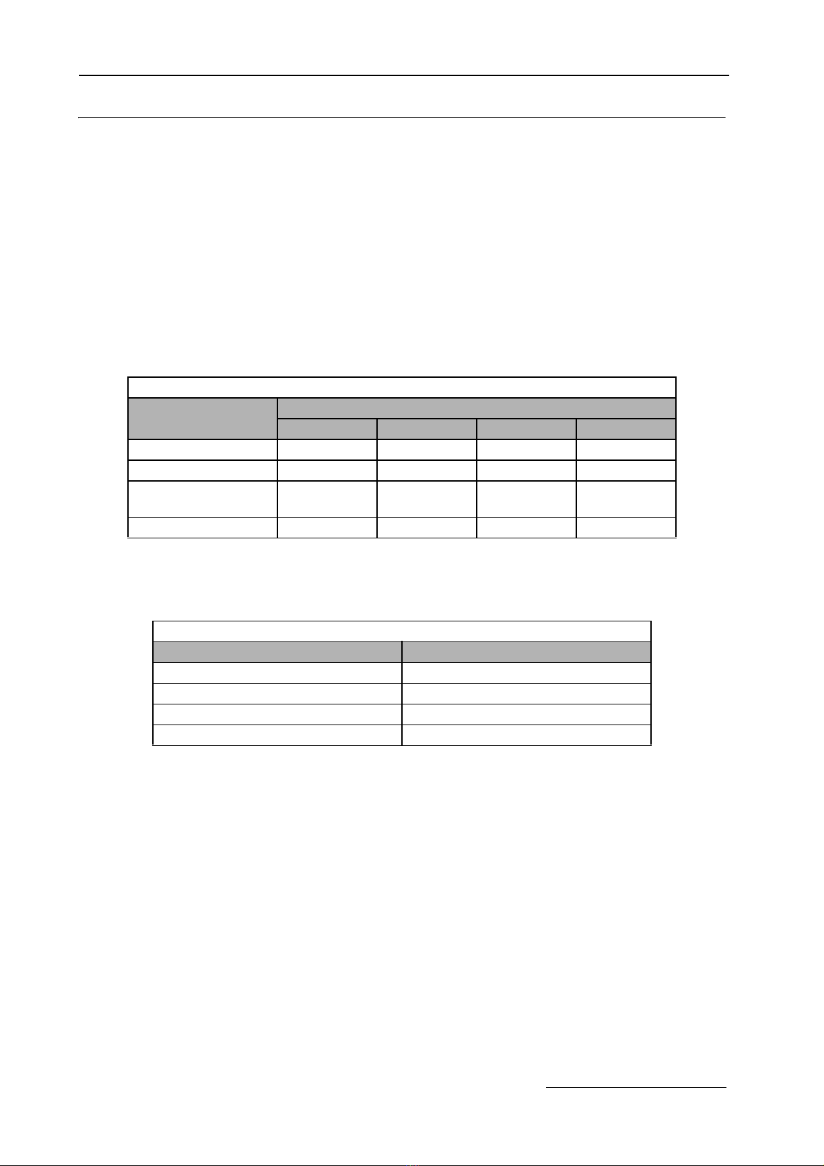
Table 1.1 Output Relays - Factory Defaults
Function Name (E7L-00) Terminal Block Terminals Type
Motor Run Motor Run * TB1 10-11 Form A
Hand Mode Relay 1 @ TB1 12-13-14 Form C
Auto Mode Relay 2 @ TB2 1-2-3 Form C
System Fault Relay 3 @ TB2 4-5-6 Form C
* = Dedicated
@ = Programmable
Table 1.2 Programmable Output Relay Functions
Function Description Factory Default
Bypass Run Annunciates running in Bypass mode No
Damper Actuator Intended to close a contact in a damper actuator circuit
whenever the motor is running (operation similar to the
dedicated “Motor Run” relay) No
Auto Transfer Annunciates automatic transfer to Bypass operation due to a
Drive fault No
Drive Run Annunciates running in Drive mode No
Serial Com Run Annunciates that the run command is coming from serial
communications No
Hand Mode Annunciates that the Drive or Bypass is being operated in
Hand (local) mode Relay 1
Auto Mode Annunciates that the Drive or Bypass is being operated in
Auto (remote) mode Relay 2
System Fault Annunciates that a Drive, motor overload or control circuit
fault has occurred Relay 3
Table 1.3 DIP Switch Settings for Output Relay Functions
No. Function Programmable
Relay 1 Programmable
Relay 2 Programmable
Relay 3 Active* Function Description
S2(6) S2(5) S2(4) S3(3) S3(2) S3(1) S3(6) S3(5) S3(4)
1Bypass Run OFF OFF OFF OFF OFF OFF OFF OFF OFF ENERGIZED Running in Bypass mode
2Damper Coil OFF OFF ON OFF OFF ON OFF OFF ON ENERGIZED Damper actuator activation
3Auto Transfer OFF ON OFF OFF ON OFF OFF ON OFF ENERGIZED Auto-Transfer is active
4Drive Run OFF ON ON OFF ON ON OFF ON ON ENERGIZED Drive is in the Run mode
5Serial Com.
Run ON OFF OFF ON OFF OFF ON OFF OFF ENERGIZED Serial Comm. Run command
6Hand Mode ON OFF ON ON OFF ON ON OFF ON ENERGIZED Manual mode operation
7Auto Mode ON ON OFF ON ON OFF ON ON OFF ENERGIZED Auto mode operation
8System Fault ON ON ON ON ON ON ON ON ON DEENERGIZED Drive, motor or control fault
Factory Settings ON OFF ON ON ON OFF ON ON ON