Wittenstein cyber motor cyber reaction wheel 2 Technical manual

Doc. no.: 5022-D060586 Revision: 02
cyber®reaction wheel 2
Project planning guide

Project planning guide cyber®reaction wheel 2
en-2 Doc. no.: 5022-D060586 Revision: 02
Revision history
Revision
Date
Comment
Chapter
01
12/08/2021
New Version
All
Technical support
In the event of technical questions, contact the following address:
WITTENSTEIN cyber motor GmbH
Sales
Walter-Wittenstein-Str. 1
D-97999 Igersheim
Tel.: +49 (0) 79 31 / 493-15800
Fax: +49 (0) 79 31 / 493-10905
Email: info@wittenstein-cyber-motor.de
If you have any questions about installation, startup or optimization, please contact our support
hotline.
WITTENSTEIN cyber motor GmbH support hotline
Tel.: +49 (0) 79 31 / 493-14800
In the event of technical malfunctions, contact us at the following address:
WITTENSTEIN cyber motor GmbH
Customer Service
Walter-Wittenstein-Str. 1
D-97999 Igersheim
Tel.: +49 (0) 79 31 / 493-15900
Email: service@wittenstein-cyber-motor.de
Copyright
© WITTENSTEIN cyber motor GmbH 2021
This documentation is protected by copyright.
WITTENSTEIN cyber motor GmbH reserves all the rights to photo-mechanical reproduction,
copying, and the distribution by special processes (such as computers, file media, data
networks), even in parts.
Subject to technical and content changes without notice.

cyber®reaction wheel 2 Project planning guide
Revision: 02 Doc. no.: 5022-D060586 en-1
Contents
1About this manual 1
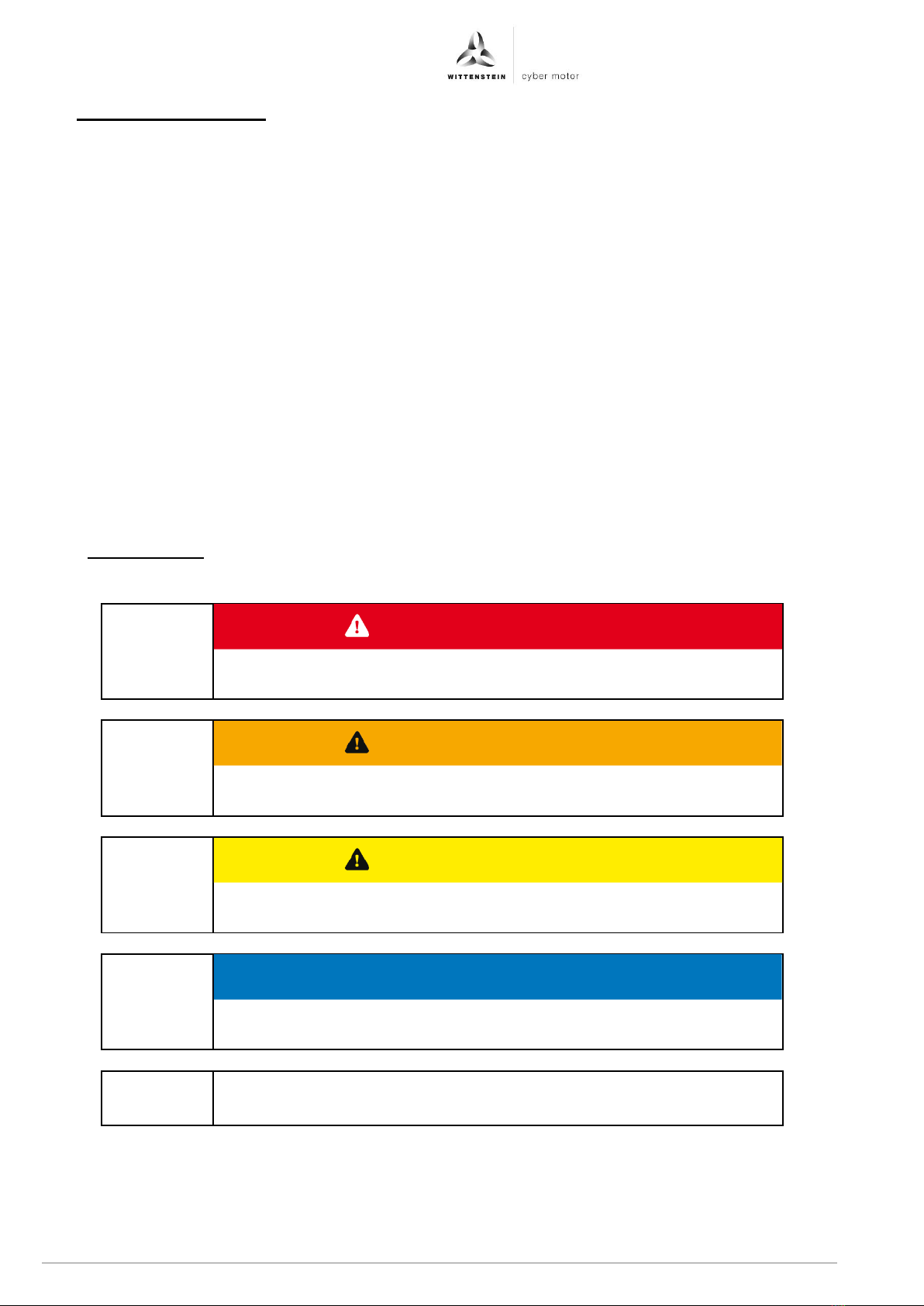
1.1 Signal words 2
1.2 Safety symbols 3
1.3 Structure of the safety information
3
1.4 Information symbols 3
2Product characteristics 4
2.1 cyber®reaction wheel 2 5
2.1.1 Type code 5
2.1.2 Name plate 6
2.1.3 Packaging and scope of delivery 6
2.1.4 System characteristics 7
2.1.4.1 DC power, torque and speed 7
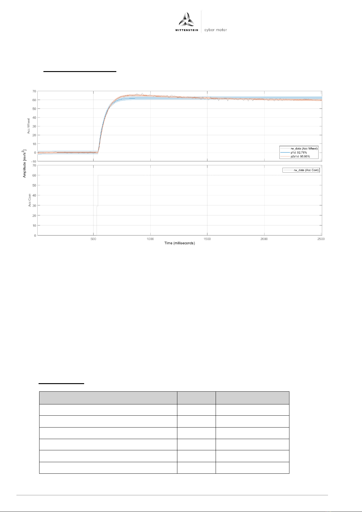
2.1.4.2 Control characteristics 8
2.1.5 Electrical data 8
2.1.5.1 Pin assignment of connector A 9
2.1.5.2 Pin characteristics of connector A 9
2.1.5.3 Use of digital IOs 10
2.1.6 Control and setpoint selection of
the reaction wheel 11
2.1.7 Ensuring availability of the
reaction wheel 11
2.1.8 Environmental conditions 12
2.1.9 Vibration/shock 12
2.1.10 Electromagnetic Compatibility
(EMC) 12
2.2 cyber®reaction wheel starter kit
13
2.2.1 Type code 13
2.2.2 Intended use 13
2.2.3 Packaging and scope of delivery 14
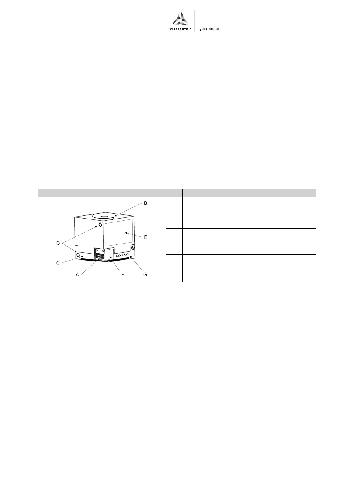
2.2.4 Structure 15
2.2.5 Electrical interfaces 16
2.2.5.1 A: USB port 16
2.2.5.2 B: Application interface 17
2.2.5.3 D: Interface to reaction wheel 18
2.2.5.4 E: Supply voltage 18
2.2.6 LEDs 19
2.2.7 Application notes 19
2.2.7.1 Setting the supply voltage 20
2.2.7.2 Provision of V-IO for the logic
blocks on the starter kit 20
2.2.7.3 Integration of digital IOs 20
2.2.7.4 UART switching 21
2.2.7.5 Brake chopper: Dissipation of
recuperation energy 21
2.2.8 Environmental conditions 22
2.3 Graphical user interface cyber®
reaction wheel assistant 23
2.3.1 Installation of the cyber®reaction
wheel assistant 23
2.3.2 CHM-Help 23
2.3.3 Oscilloscope 23
2.3.4 Setting of communication
parameters 24
2.3.4.1 Setting the I2C address 24
2.3.5 Changing important system
parameters 25
2.3.5.1 Setting the voltage limits 25
2.3.5.2 Setting speed and current limits 26
3Startup of the cyber®reaction
wheel 2 27
3.1 Safety instructions 27
3.2 Preparations 27
3.3 Startup with the cyber®reaction
wheel assistant 27
3.3.1 Installation at cyber® reaction
wheel starter kit 28
3.3.2 Establishing the power supply 28
3.3.3 Establishing a connection 28
3.3.4 Speed setting 29
3.4 Prototypical integration of the
cyber®reaction wheel 2 into an
ADCS environment 30
3.4.1 Preparations at the cyber® reaction
wheel starter kit 30
3.4.2 Example of an integration of a
reaction wheel for startup via SPI
with a Nucleo board from ST 30
3.4.3 Communication interfaces 32
3.4.3.1 I2C interface 33
3.4.3.2 SPI interface 33
3.4.3.3 UART interface 34
3.4.4 Wittenstein software stack for
integration of the reaction wheel 35
3.5 Diagnostics using the cyber®
reaction wheel assistant 35
3.6 Firmware update 36
3.6.1 Firmware update with the cyber®
reaction wheel assistant 36
3.6.2 Firmware update with ADCS 36
4Integration of the cyber®reaction
wheel 2 into a satellite 37
4.1 Electrical integration of the
cyber®reaction wheel 2 37
4.2 Mechanical integration of the
cyber®reaction wheel 2 38
4.3 Installation of the cyber®
reaction wheel 2 38
4.4 Requirements for power
adapters and supply voltage 39
4.5 Installation space 39
4.6 Mounting position 39
4.7 Cooling 39
4.8 Maintenance 39
4.9 Software-side integration in
ADCS 39

Project planning guide cyber®reaction wheel 2
en-2 Doc. no.: 5022-D060586 Revision: 02
1 About this manual
These instructions contain information required for the safe use of the cyber®reaction wheel 2
system, also referred to as the reaction wheel and the cyber®reaction wheel starter kit, also
referred to as starter kit.
The document must always be used in connection with the cyber®reaction wheel 2 operating
manual.
Each drive system is clearly described by its serial number (SN).
In case of conflict between this general operating manual and the material-specific
documentation, the material-specific documentation applies. This project planning guide is valid
for the product (drive system) unless another, material-specific documentation exists.
If this manual is supplied with amendment sheets (e.g. for special applications), then the
information in the amendment is valid. Contradictory specifications in this manual are therefore
void.
The operator must ensure that this operating manual is read through by all persons assigned to
install, operate, or maintain the drive system, and that they fully comprehend its content.
Store this manual within reach of the drive system.
Inform colleagues who work in the area around the machine about the safety instructions so
that no one sustains injuries.
The original was prepared in German, all other language versions are translations of the
original manual.
1.1 Signal words
The following signal words are used to indicate hazards, things that are forbidden and
important information:
This signal word indicates an imminent danger that will cause
serious injuries or even death.
This signal word indicates a potential hazard that could cause
serious injuries and even death.
This signal word indicates a potential hazard that could cause
minor or serious injuries.
This signal word indicates a potential hazard that could lead to
property damage.
A note without a signal word indicates application tips or especially
important information for handling the drive system.
DANGER
WARNING
CAUTION
NOTICE

cyber®reaction wheel 2 Project planning guide
Revision: 02 Doc. no.: 5022-D060586 en-3
1.2 Safety symbols
The following safety symbols are used to indicate hazards, things that are forbidden and
important information:
General danger
Hot surface
Electric voltage
Electrostatically
sensitive device
1.3 Structure of the safety information
Safety information in this manual has been structured according to the following template:
Explanatory text shows the consequences of disregarding this
information.
•Instructive text uses direct address to indicate what to do.
1.4 Information symbols
The following information symbols are used:
•Indicates an action to be performed
Indicates the results of an action
Provides additional handling information
CAUTION

Project planning guide cyber®reaction wheel 2
en-4 Doc. no.: 5022-D060586 Revision: 02
2 Product characteristics
The reaction wheel with integrated servo controller provides a defined angular momentum. It is
used to exchange an adjustable angular momentum with a satellite body. This induced angular
momentum can be used for alignment of the satellite body or for compensation of interferences
from the environment. The reaction wheel can be used in satellites with high demands for
alignment accuracy.
This document is intended to familiarize the user with the use of the cyber®reaction wheel 2.
Following the product specifications of the cyber®reaction wheel 2, the cyber®reaction wheel
starter kit and the cyber®reaction wheel assistant are the chapter on startup working with the
reaction wheel as well as prototypical integration into ADCS including a description of the
available interfaces SPI, I2C and UART.
In the end, integration into an ADCS is explained.
In addition, the software interface of the cyber®reaction wheel 2 is explained in the interface
control document.
The following table provides an initial overview of the cyber®reaction wheel 2
Designation
A
Power and signal connector
B
Housing
C
Base plate
D
Fastening screw thread
E
Name plate
F
Data Matrix code with link to service portal
G
Serial number
Table 1: Overview of the cyber®reaction wheel 2

cyber®reaction wheel 2 Project planning guide
Revision: 02 Doc. no.: 5022-D060586 en-5
2.1 cyber®reaction wheel 2
The WITTENSTEIN cyber®reaction wheel 2 is an intelligent drive system with a maximum
angular momentum of 2 mNms.
Possible communication interfaces are SPI, I2C and UART.
The intelligence is reflected in an encoderless control system with a high diagnostic depth and
the range of functions of industrial drive technology. The sign change of the angular momentum
as well as the operation throughout the angular momentum range can be done without any
limitations.
Intuitive startup and integration of the drive system is made possible by the cyber®reaction wheel
starter kit with the PC-based, graphical user interface cyber®reaction wheel assistant. It includes
a wide range of options for parameterization, diagnostics and control. The CHM help is also part
of the cyber®reaction wheel assistant.
Alternatively, the reaction wheel can be easily started up with a microcontroller using the cyber®
reaction wheel starter kit. For this, WITTENSTEIN cyber®motor offers a communication stack
that ensures easy integration into an ADCS.
Both possibilities for startup are described in sections 3.3 and 3.4.
2.1.1 Type code
Figure 1.1: crw type code

Project planning guide cyber®reaction wheel 2
en-6 Doc. no.: 5022-D060586 Revision: 02
2.1.2 Name plate
The name plate consists of a laser inscription on the motor housing.
Designation
1
Product designation
2
Calendar week and year of production
3
DC bus voltage UDC
4
Maximum power Pmax, el
5
No-load speed n0
6
DC bus current IDC
7
Angular momentum Ln
8
Mass m
9
Maximum torque Mmax
10
Protection class
11
Manufacturer
12
Data Matrix code: Serial number
Table 2: Name plate of cyber®reaction wheel 2
Customized deviations are permissible.
The Data Matrix code (DMC) under the name plate is in the format C18x18 according to ECC200.
It contains the Service Portal Address including the Service Portal Code.
2.1.3 Packaging and scope of delivery
The drive system is delivered packed in foil and/or cardboard boxes.
•Dispose of the packaging materials at the recycling sites intended for this purpose.
Please observe the valid national regulations for waste disposal.
•Check the completeness of the delivery against the delivery note.
Immediately notify the carrier, the insurance company, or
WITTENSTEIN cyber motor GmbH in writing of any missing parts or damage.

cyber®reaction wheel 2 Project planning guide
Revision: 02 Doc. no.: 5022-D060586 en-7
2.1.4 System characteristics
The maximum admissible technical data is described in the following table 3
For additional information, please contact our sales department. Always state the serial number
(SN) when doing so.
System data
Unit
Value
Angular momentum at 18000 rpm
mNms
2
Max. speed
rpm
19000
Nominal speed
rpm
18000
Nominal power1
W
0.2
Max. acceleration time to 18000 rpm
s
7
Max. acceleration
rev/s²
60
Max. deceleration with recuperation
rev/s²
60
Max. deceleration without recuperation
rev/s²
30
Weight
g
30
Max. static imbalance
gmm
0.02
Max. dynamic imbalance
gmm²
0.2
Table 3: System characteristics of cyber®reaction wheel 2
2.1.4.1 DC power, torque and speed
The following figure shows the DC power and torque against the speed at different accelerations.
Figure 1.2: DC power and torque profiles against the velocity at accelerations of the cyber®reaction wheel 2 from 0 rev/s² to
60 rev/s² at UDC = 5 V
1
The rated connection power refers to operation at a stationary velocity of 8000 rpm with run-in bearings and an intermediate
circuit voltage of 5 V. After an extended standstill, power consumption may be temporarily increased.

Project planning guide cyber®reaction wheel 2
en-8 Doc. no.: 5022-D060586 Revision: 02
2.1.4.2 Control characteristics
According to the following figure, the cyber®reaction wheel 2 can be approximated as a first or
second order system.
Figure 1.3: Illustration of the step response of the cyber®reaction wheel 2 at an acceleration jump from 0 rev/s² to 60 rev/s²
Wittenstein recommends using a transfer function second order with the following parameters for
simulation to better map the settling time:
1+Tz*s
G(s) = Kp * -------------------------------- * exp(-Td*s)
1+2*Zeta*Tw*s+(Tw*s)^2
Kp = 0.983
Tw = 0.228
Zeta = 1.867
Td = 0.01
Tz = 0.908
SettlingTime: ~1.7
Overshoot: ~10 %
2.1.5 Electrical data
Electrical data
Unit
Value
Nominal supply voltage
V DC
5
Supply voltage range
V DC
3.0…8.8
Max. power input (configurable)
mW
<2000
Inrush current power off/on
mA
480
Inrush current disable/enable
mA
560
Plug-in cycles for connector A
number
max. 30
Table 4: Overview of electrical data of the cyber®reaction wheel 2

cyber®reaction wheel 2 Project planning guide
Revision: 02 Doc. no.: 5022-D060586 en-9
2.1.5.1 Pin assignment of connector A
Figure
Pin no.
Signal name
Function
17
GND
Ground reference
18
GND
Ground reference
1
Chopper_Ena
Output signal, underclocking
2
I2C_SCL
I2C bus SCL
3
IO_1
User Output 1
4
I2C_SDA
I2C bus SDA
5
CAN_Rx
Reserved for CAN Rx
6
SPI_MOSI
SPI Bus MOSI
7
CAN_Tx
Reserved for CAN Tx
8
SPI_MISO
SPI Bus MISO
9
UART_Tx
UART Tx
10
SPI_nCS
SPI Bus Chip-Select
11
UART_Rx
UART Rx
12
SPI_CLK
SPI Bus Clock
13
USB_M
Reserved for USB D-
14
USB_P
Reserved for USB D+
15
IO_2
User Output 2
16
IO_3
User Input 1
19
VDD
Supply voltage
20
VDD
Supply voltage
Connector type for connection of cyber®reaction wheel 2: MOLEX SlimStack
PCB connector (16+2) 505070-1622
For alignment of the connector on the drive system, see dimensional drawing,
document number 5007-D060499.
Table 5: Pin assignment of connector A at the cyber®reaction wheel 2
2.1.5.2 Pin characteristics of connector A
Direction
Size
Value
Affected pins
General limits
Input
Maximum voltage for
low level
1.2 V
2, 4, 5, 6, 10, 11, 12,
13, 14
Permitted voltage range
of inputs: 0 V - 3.6 V
Minimum voltage for
high level
1.9 V
Output
Maximum voltage at
low level
0.4 V
1, 3, 4, 7, 8, 9, 15
Permitted maximum
current of outputs:
±4 mA each
Minimum voltage at
high level
2.4 V
Table 6: Pin characteristics of connector A at the cyber®reaction wheel 2

Project planning guide cyber®reaction wheel 2
en-10 Doc. no.: 5022-D060586 Revision: 02
2.1.5.3 Use of digital IOs
The digital IOs user output 1, user output 2 and user input 1 specified in the tables 5 and 6 can
be functionally configured by the user. The configuration options are documented in the CHM
help in the cyber®reaction wheel assistant.
To do so, simply tap digital IO help and configure the digital IOs within the digital IO tile (1).
Figure 1.4: Display and application of the configuration options
of the digital IOs for the cyber® reaction wheel 2
For information on how the digital IOs can best be integrated into the application, please refer to
section 2.2.7.3.
The configuration example below describes use of the reaction wheel with the cyber®reaction
wheel starter kit:
As described in table 17,
- User output 1 is wired to a red LED
- User output 2 is wired to a green LED
on the cyber®reaction wheel starter kit.
In this configuration example, the red LED lights up in case of a fault in the drive and the green
LED as soon as the setpoint velocity is reached:
Figure 1.5: Configuration example of user output 1 and 2 for the cyber® reaction wheel 2 for displaying an error with the red
LED and displaying the velocity status with the green LED during operation with the cyber® reaction wheel starter kit
(1)

cyber®reaction wheel 2 Project planning guide
Revision: 02 Doc. no.: 5022-D060586 en-11
2.1.6 Control and setpoint selection of the reaction wheel
The software of the reaction wheel offers numerous options for control and diagnostics.
For this purpose, the reaction wheel is operated in velocity control mode.
For specification of the angular momentum, acceleration, deceleration and a velocity setpoint are
specified. The velocity setpoint is then approached with the set gradients. Changing the velocity
of the rotating inertia causes an angular momentum of the required value and in the required
direction.
A positive value of the velocity results in revolution of the rotor in counterclockwise direction when
viewing the housing from above (see table 1). Respectively, entering of a positive acceleration
results in a clockwise reaction torque to the application.
The change velocity (acceleration/deceleration) of the angular momentum as well as the velocity
setpoint can be set as required within the limits defined in table 3.
Chapters 3 and 4 describe in detail the options for initial startup and integration of the
reaction wheel:
•Initial startup with the cyber®reaction wheel assistant (see section 2.3) and the cyber®
reaction wheel starter kit (see section 2.2) within a few minutes: Section 3.3
•Startup with the cyber®reaction wheel starter kit and a microcontroller for prototypical
integration into an ADCS: Section 3.4.
•Integration of the cyber®reaction wheel 2 into an ADCS: Chapter 4
Installation of the cyber®reaction wheel assistant (see section 2.3) provides automatic access to
the CHM help in addition to the options for easy startup and diagnostics.
2.1.7 Ensuring availability of the reaction wheel
The reaction wheel has implemented numerous mechanisms to maximize availability.
These include:
- Temperature, current and voltage monitoring
- Monitoring of internal voltage references and power supply units
- Monitoring of FLASH and RAM memory as well as correction of corrupt addresses
- Fault memory for detailed diagnostics, see CHM help of the cyber®reaction wheel assistant
Wittenstein strongly recommends maintaining the voltage supply to the reaction wheels at all
times. This is the only way to ensure that the monitoring and repair mechanisms mentioned
above are functional and that the availability of the reaction wheel is maximized.
Energy consumption is therefore reduced to a minimum during no-load operation of the
reaction wheels.

Project planning guide cyber®reaction wheel 2
en-12 Doc. no.: 5022-D060586 Revision: 02
2.1.8 Environmental conditions
The cyber®reaction wheel 2 can be stored on the ground for 2 years before use.
Environmental conditions
Unit
Value
Operating ambient temperature range
°C
-40 … 852
Survival ambient temperature range
°C
-40 … 100
Nominal ambient temperature range3
°C
0 … 55
Max. radiation dose
Gy
200
Minimum ambient pressure
mbar
10-8
Table 7: permitted ambient conditions
2.1.9 Vibration/shock
The drive system fulfills the following specifications:
•Vibration according to DIN EN 60068-2-6:2008
- Frequency range 5 Hz –2000 Hz
- Acceleration: 1 g –8 g
•Broadband noise according to DIN EN 60068-2-64:2008
- Frequency range 20 Hz –2000 Hz
- Acceleration RMS: 7.5 g
•Shock according to DIN EN 60068-2-27:2009
- Shock form: semi-sinusoidal
- Acceleration: 40 g
- Shock duration: 3 ms
2.1.10 Electromagnetic Compatibility (EMC)
The system meets the requirements for interference immunity according to EN 61000-4-3
(electromagnetic HF field) and EN 61000-4-4 (fast transients) as well as interference emissions
according to EN 55011 (interference voltage at the power supply connection and radiated
interference emission).
2
At 85 °C, a permanent acceleration and deceleration of 10 rev/s² is possible for the speed range from -1500 rpm to 1500 rpm.
Between 1500 rpm and 10000 rpm, a permanent acceleration and deceleration of 60 rev/s² is possible.
3
In this temperature range, the crw can be operated continuously over the complete speed range with the maximum
acceleration of 60 rev/s² if the thermal connection is sufficient.

cyber®reaction wheel 2 Project planning guide
Revision: 02 Doc. no.: 5022-D060586 en-13
2.2 cyber®reaction wheel starter kit
The WITTENSTEIN cyber®reaction wheel starter kit is a startup platform for the cyber®
reaction wheel 2. This platform makes it very easy to start up the reaction wheel via USB and the
cyber® reaction wheel assistant. The voltage can be supplied via USB port or alternatively via an
external power supply unit.
For connection of the cyber® reaction wheel 2 to a microcontroller (e.g. an ADCS), all signals at
connector B are routed to the outside (see table 9).
This chapter describes the detailed structure of the starter kit and its intended use. Chapter 3
describes the various options for startup and integration of the cyber®reaction wheel 2 with the
cyber®reaction wheel starter kit.
Section 2.2.7 presents application examples for implementation and verification with the
starter kit.
2.2.1 Type code
Figure 1.6: crws type code
2.2.2 Intended use
The cyber®reaction wheel starter kit is intended exclusively for startup of the cyber®reaction
wheel 2. Integration of the cyber®reaction wheel starter kit into any commercially available
products is not permitted.

Project planning guide cyber®reaction wheel 2
en-14 Doc. no.: 5022-D060586 Revision: 02
2.2.3 Packaging and scope of delivery
On delivery, the cyber®reaction wheel starter kit is packaged in foil and/or cardboard.
•Dispose of the packaging materials at the recycling sites intended for this purpose.
Please observe the valid national regulations for waste disposal.
•Check the completeness of the delivery against the delivery note.
Immediately notify the carrier, the insurance company, or
WITTENSTEIN cyber motor GmbH in writing of any missing parts or damage.
cyber® reaction wheel starter kit
- 1 PCB for startup
- 1 USB cable
- 2 screws, DIN 912 M2x4, for mounting the cyber®reaction wheel 2

cyber®reaction wheel 2 Project planning guide
Revision: 02 Doc. no.: 5022-D060586 en-15
2.2.4 Structure
Table 8 and figure 1.7 provide an overview of the starter kit and its interfaces.
Designation
A
USB port
B
Application interface
C
Only for manufacturer
D
Interface to reaction wheel
E
Supply voltage
F
Slot for reaction wheel
G
Fixing bores for starter kit
H
Screws DIN 912 M2x4
I
Reaction wheel (not included in the scope
of delivery of the cyber® reaction wheel
starter kit)
Table 8: Overview of external interfaces of the starter kit
Figure 1.7: Illustration of the external interfaces of the cyber®reaction wheel starter kit
B
A
C
D
E
F
F
G
G
G
G
1

Project planning guide cyber®reaction wheel 2
en-16 Doc. no.: 5022-D060586 Revision: 02
2.2.5 Electrical interfaces
The following section describes the electrical interfaces as shown in figure 1.7 at the starter kit as
well as their properties.
Connector
Function
Plug connector type
crws
Plug connector type
remote end
A
USB port
Mini-USB B socket
Mini USB connector
B
Application interface
Pin connector, 20-pin,
male, grid 2.54 mm
Socket strip, 20-pin, female,
grid 2.54 mm
C
Programming
interface
Only for manufacturer
D
Interface to reaction
wheel
MOLEX SlimStack PCB
connector (16+2)
5050701622
MOLEX SlimStack PCB
connector (16+2)
5050661622
E
Supply voltage
2-pin screw terminal
Open cable
Table 9: Overview of starter kit plug connectors
2.2.5.1 A: USB port
The USB port is used for easy startup,
- for communication with the cyber®reaction wheel assistant, see section 3.3,
- as well as for voltage supply (if necessary, derating the reaction wheel due to available
power of the USB voltage source)
- and for diagnosis of the reaction wheel during integration, see section 3.5
The USB interface is based on a FT232R USB-to-serial UART interface from FTDI.
In the customer application, the pins UART Rx/Tx can be controlled directly, see section 2.2.7.4.
Connection
Property
Unit
Minimum
value
Nominal
value
Maximum
value
USB 2.0
Voltage supply and/or
communication
interface for startup
tool
V
5.0
Table 10: Electrical properties of application interface, connector B, at the cyber®reaction wheel starter kit

cyber®reaction wheel 2 Project planning guide
Revision: 02 Doc. no.: 5022-D060586 en-17
2.2.5.2 B: Application interface
Application interface B, see figure 1.7, is intended for fast and prototypical integration of the
reaction wheel into the target application. Section 3.4 describes how this is to be done.
All signals listed below have an ESD protection diode.
Figure
Pin no.
Signal name
Function
1
GND
Ground reference
2
GND
Ground reference
3
Chopper_Ena
Activation of
underclocking (Out)
4
I2C_SCL
I²C Bus SCL (In)
5
IO_1
User Ouput 1
6
I2C_SDA
I²C Bus SDA (Bi)
7
Reserved
Reserved for CAN Rx
(In)
8
SPI_MOSI
SPI Bus MOSI (In)
9
Reserved
Reserved for CAN Tx
(Out)
10
SPI_MISO
SPI Bus MISO (Out)
11
UART_Tx
Serial interface (Out)
12
SPI_nCS
SPI Bus Chip-Select (In)
13
UART_Rx
Serial interface (In)
14
SPI_CLK
SPI Bus Clock (In)
15
Reserved
Reserved for USB D-
(Bi)
16
Reserved
Reserved for USB D+
(Bi)
17
IO_2
User Ouput 2
18
IO_3
User Input 1
19
V-IO
Logic supply
20
VDD
Reaction wheel supply
Table 11: Pin assignment of application interface, connector B, at the cyber®reaction wheel starter kit
Connection
Property
Unit
Minimum
value
Nominal
value
Maximum value
V-IO
Voltage
V
3.0
3.3 / 5.0
5.5
VDD
Voltage
V
3.0
5.0
8.8
Chop_Ena
Voltage
V
Corr. to V-IO
I2C_xx
Voltage
V
Corr. to V-IO
User_IO_x
Voltage
V
3.0
3.3
3.6
CAN_xx
Voltage
V
Corr. to V-IO
SPI_xxx
Voltage
V
Corr. to V-IO
UART_xx
Voltage
V
Corr. to V-IO
USB
Voltage
V
typ. USB
Table 12: Electrical properties of application interface, connector B, at the cyber®reaction wheel starter kit
B

Project planning guide cyber®reaction wheel 2
en-18 Doc. no.: 5022-D060586 Revision: 02
2.2.5.3 D: Interface to reaction wheel
Figure
Pin no.
Signal name
Function
17
GND
Ground reference
18
GND
Ground reference
1
Chopper_Ena
Activation of
underclocking
2
I2C_SCL
I²C Bus SCL
3
IO_1
User Ouput 1:
red LED on starter kit
4
I2C_SDA
I²C Bus SDA
5
Reserved
Reserved for CAN Rx
6
SPI_MOSI
SPI Bus MOSI
7
Reserved
Reserved for CAN Tx
8
SPI_MISO
SPI Bus MISO
9
UART_Tx
Serial interface
10
SPI_nCS
SPI Bus Chip-Select
11
UART_Rx
Serial interface
12
SPI_CLK
SPI Bus Clock
13
Reserved
Reserved for USB D-
14
Reserved
Reserved for USB D+
15
IO_2
User Ouput 2:
green LED on starter kit
16
IO_3
User Input 1
19
VDD
Reaction wheel supply
20
VDD
Reaction wheel supply
Connector type at starter kit: MOLEX SlimStack PCB connector (16+2)
5050701622
Table 13: Pin assignment of interface to reaction wheel, connector D, at the cyber®reaction wheel starter kit
•Observe the maximum number of 30 plug-in cycles for the interface to the reaction wheel.
Connection
Property
Unit
Minimum
value
Nominal
value
Maximum value
Signals 1-16
Voltage
[V]
3.0
3.3
3.6
VDD
Voltage
[V]
3.0
8.8
Table 14: Electrical properties of application interface, connector D, at the cyber®reaction wheel starter kit
2.2.5.4 E: Supply voltage
Besides voltage supply via USB port (A), see section 2.2.5.1, a power supply unit can also be
used directly. This is recommended if the reaction wheel is operated very dynamically, as the
power supplied from the USB port is not sufficient for stable supply of the reaction wheel at every
operating point.
Figure
Pin no.
Signal
Function
1
VDD
Supply
2
GND
Ground reference
Connector type at starter kit: 2-pin screw terminal
Table 15: Pin assignment of supply voltage, connector E, at the cyber®reaction wheel starter kit
Connection
Property
Unit
Minimum
value
Nominal
value
Maximum
value
VDD
Voltage
[V]
3.0
5.0
8.8
Table 16: Electrical properties of supply voltage, connector E, at the cyber® reaction wheel starter kit
Table of contents
Other Wittenstein cyber motor DC Drive manuals