Toyota 7FBEF 15 User manual

Index
< Tillbaka till Servicemanual 7FBEF 15-20

FOREWORD
This manual mainly describes the development objectives of new Toyota forklift
7FBEF15 to 20 models, outlines of main component units, structures and functions of
new mechanisms and other technical features.
Please read it carefully for sales and service activities.
This manual has been edited for the vehicles launched into the market in May
2003.
Any later change shall be informed through Toyota Industrial Equipment Parts &
Service News.
Please refer to the repair manual and parts catalog for the matters necessary
for servicing.
TOYOTA Material Handling Company
A Division of TOYOTA INDUSTRIES CORPORATION

SECTION INDEX
NAME SECTION
GENERAL 0
DEVELOPMENT OBJECTIVE 1
ELECTRICAL SYSTEM 2
POWER TRAIN 3
TRAVELING, STEERING AND BRAKE SYSTEMS
4
INSTRUMENTS 5
FRAME AND AUXILIARY EQUIPMENT 6
MATERIAL HANDLING AND HYDRAULIC SYSTEM
7
SAS CONTROL SYSTEM 8
OUTLINE OF MAJOR OPTIONS 9
APPENDIX 10

0-1
GENERAL
Page
VEHICLE EXTERIOR VIEWS ...................................... 0-2
MODEL LINEUP.............................................................. 0-3
2
3
0
3

0-2
VEHICLE EXTERIOR VIEWS
■ Vehicle exterior views
Front View
Rear View

0-3
MODEL LINEUP
■Vehicle model lineup
L.C.: Load center
Payload
(L.C. 500 mm) New model Previous model Voltage
1.5 ton 7FBEF15 5FBE15 48V
1.6 ton 7FBEF16 −48V
1.8 ton 7FBEF18 5FBE18 48V
2.0 ton 7FBEF20 −48V
2
3
0
3

0-4

1-1
DEVELOPMENT OBJECTIVE
Page
DEVELOPMENT OBJECTIVE..................................... 1-2
FEATURES (SELLING POINTS) ................................ 1-3
MAJOR DIFFERENCES BETWEEN NEW AND
PREVIOUS MODELS ................................................. 1-9
2
3
1

1-2
DEVELOPMENT OBJECTIVE
■Development objective
Toyota 5FBE series, 1,500-kg to 1,800-kg three-wheel, counter battery type forklift have favorably been
accepted by a large number of customers thanks to their ease of use and reliability since the model
change in 1993.
After the model changes by competitors in later years, however, disparities in specifications and
equipment compared to 7FB series and 7FBR series have been pointed out.
Growing environmental concerns in the market, on the other hand, has been adding to the importance of
battery vehicles.
■Development concepts
The AC drive system, especially was implemented in 1999 ahead of other companies by consolidation of
our time-tested technologies. Its features have fully been utilized not only in performances but also in
operating feel.
We propose these models as three-wheel counter battery forklift trucks without an equal in performance
and operating feel.
1Optimum material handling operation matching each customer's needs by making the most of
the features of AC-motor drive system.
2
Adoption of the SAS (mast control and steering synchronizer) developed in the 7 series and
highly evaluated in the market for realization of high stability comparable with that of the 7
series.
3Easier ingress and egress by adoption of the open step, small-diameter steering wheel and tilt
steering with memory.
4Addition of 1,600- and 2,000-kgf models to the 1,500- and 1,800-kgf models in the previous
series.

1-3
FEATURES (SELLING POINTS)
■Major selling points
The greatest feature of the new models is adoption of the AC motor drive system. New features of the 7FB
series have also been adopted in many places.
1. Adoption of AC Motor Drive System
What is AC motor drive system?
The conventional DC motor drive system uses a controller for battery current chopping (ON and OFF)
to control the motor power by changing the chopping ratio to realize from inching at the time of starting
up to the maximum power.
The controller in the AC motor drive system converts the battery current to a three-phase alternate
current, whose sine wave form (frequency and waveform height) varies to control the motor power.
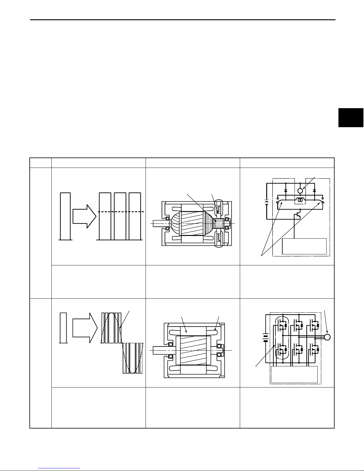
The table below compares the motor voltage, motor structure and the controller between the AC
system and DC system.
Comparison between the DC and AC systems
Motor voltage Motor structure Controller
DC
sys-
tem
• Conversion from battery DC
voltage into the mean volt-
age by the chopper
• Need of brush and commu-
tator maintenance
• Complicated structure
• Relatively easy by mean DC
voltage control
• Need of contactor for rotat-
ing direction change
AC
sys-
tem
• Conversion from battery DC
voltage into the AC voltage
by the controller
• No brush and commutator
(maintenance-free)
• Compact and lightweight
• Conversion from DC into
three-phase AC by the mod-
ule
• No need of contactor for
rotating direction change
Battery voltage Motor voltage
Con-
troller
Mean voltage
ON ON ON
Commutator Brush M
Motor
Contactor
Microcomputer
control
Battery
Battery voltage
Con-
troller
Motor voltage
Sine wave Stator core Stator coil
M
Microcomputer
control
Motor
1 Phase
Battery
2
3
1

1-4
Features of AC motor drive system
The table below shows three major features of the AC motor drive system. The AC motor drive system
has already been adopted in the industrial world by making the most of these features.
It has been known to worldwide forklift engineers that the AC motor drive system, as stated above, is a
very excellent system for battery forklift trucks.
Selling points of the new models fully utilizing these features are explained below.
2. Power Select Function
The performance best matching the operator can be selected by single switch operation.
The traveling performance in loaded state is improved in new models by making the most of the
simple, compact structure of the AC motor. One switch selects any of the following modes.
• Mobility-preference mode featuring the shortest cycle time (H mode)
• Efficiency-preference mode for short cycle time and long working hours (P mode)
• Operation-hour-preference mode featuring the longest operation hours with the performance
equivalent to that of previous models (S mode)
To satisfy individual customer requirements, a power control select function is provided for setting the
traveling mode by selection from six modes including H, P and S.
The operation efficiency is greatly improved by selection of the optimum performance for each
customer need like H mode selection for a job requiring the power and performance or S mode
selection for continuous operation for many hours.
Power select function
System feature Product feature
1 Simple, compact motor structure Realization of higher performance in the same
product size
2Realization of new control by three-phase
AC control
Realization of new performance and feel thanks
to wider motor control range
3 No motor brush and contactor Reduction of maintenance cost for motor brush
and contactor
[7FBEF15]
Cycle time
(sec/cycle)
85
90
95
[H mode]
[P mode]
[S mode]
Previous model
180min 260min
220min 300min Operation time
(DIN 4PzS 440L)
:Fixed mode

1-5
Especially, the loaded traveling and material handling performances in the H mode have been
improved over 30%. As a result, our 30-m operation cycle time has been shortened by about 10% or
more.
Traveling speed
Km/h
NL16.5
15.0
14.0 13.5
16.0
12.5 12.5
30%UP
14.0
11.5
FL15.0
H mode P mode S mode 5FBE15
H mode P mode S mode 5FBE15 H mode P mode S mode 5FBE15
STILL R20
H mode P mode S mode 5FBE15 STILL
mm/sec
NL610
540
480 480
600
420
260
FL430
NL: No load
FL: Full load
NL: No load
FL: Full load
280
350
65%UP
Cycle time
(TOYOTA 30m operation cycles)
sec/cycle
85
11%UP
91
95 95 min
185
240
270
230
Operation time
(DIN 4PzS 440L, TOYOTA 30m operation cycles)
Lifting speed
1.5 ton 2
3
1

1-6
3. Improved Efficient Operation Hour
The accelerator-off regeneration system is added to the AC drive system for longer operation
compared to the previous models. The power up function is also adopted for longer efficiency
operation hours.
Power keep function
(Setting to the P mode at the Efficiency-preference and the S mode for Operation-hour-preference)
The power keep function has been developed as the new control in new models for maintaining the
discharged battery performance by making use of the wider motor control range of the AC motor drive
system.
• The efficiency operation hours allowing operation without feeling performance degradation
is improved by 40% by adoption of the power keep function and extension of the operation
hours.
• The number of operation cycles without feeling performance degradation is also improved by
40%.
This new function actually improves the operation efficiency at each customer greatly.
However, note that efficient operation becomes hard when the battery level indicated by the battery
charge indicator becomes one bar (battery discharge to about 90%).
1.1
1
0.9
0.8
0.7
0% 20% 40% 60% 80% 100%
Decrease in
performance
Low remaining battery charge warning
Previous model (1.5t)
Efficiency operation hour:2H20m
(440AH/5hr)
Previous model (1.5t:S mode)
Efficiency operation hour:3H20m
(440AH/5hr)
New model
Previous model
Battery discharge level (%)
Battery usage
limit range
Full load performance
Lift interruption
25%UP
40%UP
52% UP
17% UP
min
350
270
230
7FBEF15 5FBE15
(DIN 5PzS550L)
S mode
7FBEF15
(DIN 4PzS440L)
S mode
1.5 ton

1-7
4. Easy Ingress/Egress and Dwelling Ability
Easy Ingress/Egress
An open step is provided for easy ingress/egress.
The tilt steering is also provided with a memory as on the 7FB series to allow full forward tilting of the
steering column to ensure smoother ingress/egress.
Step height
Dwelling Ability
Compared to previous models, the head clearance is increased by 25 mm (0.98 in) to 1,025 mm (40.4
in).
5. Maintenance Cost Reduction
Maintenance items specific to battery vehicles are as follows:
1) Addition of distilled water for battery
2) Pump motor brush replacement
3) Pump contactor replacement in controller
4) Drive motor brush replacement
5) Drive contactor replacement in controller
Since the AC motor has no brush and contactor as explained earlier, brush replacements are
unnecessary. Depending on the operating conditions at each customer, the annual maintenance cost
can be reduced as much as 80%.
The newly adopted acceleration-off regeneration system regenerates the electrical braking energy
upon accelerator pedal release during traveling in the battery by making the most of the wider motor
control range of the AC motor drive system. This accelerator-off regeneration system not only extends
the operation hours and improves the running stability by electrical braking but also reduces the brake
load and lining wear for less brake maintenance cost.
New model
Step height
430mm
Step height
545mm
(16.9in)
(21.5in)
Previous model

1-8
6. Safety Functions
The new models are installed with the SAS safety functions adopted on the 7FB series to ensure
equivalent safety. Though the safety functions are summarized below, refer to the SAS Control
Equipment section for further details.
Safety Function List
On three-wheel battery counter vehicles, the automatic control rear stabilizer is not provided because
of no rear wheel swing mechanism.
7. Anti-rollback
A function for easy starting on a slope (reduction of rollback on a slope) is provided.
8. Model Series
The 1.6- and 2.0-ton models have been developed anew to enrich the model line-up.
The 1.0- and 1.25-ton models have been discontinued.
9. Maximum battery capacity
The battery compartment length in the longitudinal direction has been widened by 87 mm on the 1.5-
ton model and 193 mm on the 1.8-ton model to accept the same DIN-size batteries for the STILL R20
on all series models.
Safety control Functional outline
Mast
con-
trol
Active mast front tilt angle control
Decreases the front tilt angle at a high fork height
or under a heavy load, and increases it at a low
fork height or under a low load.
Active mast backward tilt speed control Retards the backward tilting speed at a high fork
height, and increases it at a low fork height.
Key-lift interlock
If the key switch is in the OFF position, the lift
operation is disabled even when the material han-
dling lever is operated.
Automatic fork leveling control
Forward tilting by pressing the button causes the
mast to be stopped automatically when the fork is
leveled.
Steering synchronizer (EHPS) The steering knob is not shifted during full
hydraulic power steering.
EHPS: ELECTRONICALLY CONTROLLED FULLY-HYDRAULIC POWER STEERING
1000 1250 1500 1600 1800 2000
Capacity (kgf)
7FBE
5FBE
: Continuation : New
1500 1600 1800 2000
5PzS550L 6PzS660L 6PzS660L 6PzS660L
4PzS440L 4PzS440L
Capacity (kgf)
7FBE
5FBE

1-9
MAJOR DIFFERENCES BETWEEN NEW AND PREVIOUS MODELS
−:Not applicable
Item
New models Previous models
Applicable
models
Applicable
models
General
Wheel base 1385 mm 1.5 ton 1295 mm All models
1490 mm 1.6 to 2.0 ton −−
Overall width 1070 mm 1.5 to 1.8 ton 1075 mm All models
1125 mm 2.0 ton −−
Overall height 1980mm All models 1950mm All models
Motor
Drive motor AC: 4.9 kW ×2 All models DC: 3.3 kW ×2 All models
Pump motor AC: 9.2 kW All models DC: 8 kW All models
PS motor −−DC: 0.75 kW All models
Controller Main controller
Traveling, material
handling and steer-
ing control
All models Traveling/material
handling control All models
Steering controller −All models Contactor type All models
Traveling sys-
tem
Steering system Steering synchro-
nizer, EHPS system All models FHPS system All models
Parking brake lever Parking brake lever
ratchet type All models Parking brake lever
ratchet type All models
Tires
Front tire 18 × 7−8 1.5 to 1.8 ton 18 × 7−8-14PR 1.5 ton
200/50-10 2.0 ton 18 × 7−8-16PR 1.8 ton
Rear tire 15 × 4.1/2-8(dual) 1.5 to 1.8 ton 16 × 6-8-10PR(dual) All models
16 × 6-8(dual) 2.0 ton
SAS equip-
ment SAS specifications
Mast control
• Active mast front
tilt angle control
• Mast backward
tilt angle control
• Automatic fork
leveling control
• Key-lift interlock
All models −−
Steering synchro-
nizer EHPS All models −−
Frame Head clearance 1025mm All models 1000mm All models
Step height 430mm All models −−
Auxiliary
equipment
Rear combination
lamp
High-mount embed-
ded type All models Add-on type All models

1-10

2-1
ELECTRICAL SYSTEM
Page
BATTERY.......................................................................... 2-2
MOTORS........................................................................... 2-4
MAIN CONTROLLER .................................................... 2-10
2
3
2

2-2
BATTERY
■General
1. Battery Compartment and Necessary Weight
When purchasing the battery locally, always adjust the weight to satisfy the minimum weight shown in
the table below.
Vehicle model Compartment dimensions mm (in) Minimum required battery
weight (with case) Kg (lb) Remarks
Length X Width Y Height Z
STD 7FBEF15 630 (24.8) 830 (32.7) 627 (24.7) 830 (1830)
7FBEF16 to 20 738 (29.1) ↑↑ 985 (2172)
R/O 7FBEF15 630 (24.8) ↑↑ 830 (1830)
7FBEF16 to 20 738 (29.1) ↑↑ 985 (2172)
R/O: Battery roll-out specifications
Width
Y
Height
Z
Length
X

2-3
2. Battery Specifications
No batteries are provided.
Please use the batteries conforming to DIN 43 531A.
Use 320A connectors.
3. Battery List
The table below shows recommended batteries.
Refer to the general description for batteries with regard to the minimum required weight.
DIN 43 531A
Vehicle models Voltage
Installed battery Battery case
Supplier Model Capacity
[AH/5HR]
Dimensions mm (in)
length width height
7FBEF15 48
VARTA 5PzS550L 550 630 (24.8) 830 (32.7) 627 (24.7)
5PzS600Hx 600 ↑↑↑
OLDHAM 24CYQ5 500 ↑↑↑
24CYH5 550 ↑↑↑
CHLORIDE 5PzS500 500 627 (24.7) ↑↑
5PzS550H 550 ↑↑↑
7FBEF16 to 20 48
VARTA 6PzS660L 660 738 (29.1) 830 (32.7) 627 (24.7)
6PzS720Hx 720 ↑↑↑
OLDHAM 24CYQ6 600 ↑↑↑
24CYH6 660 ↑↑↑
CHLORIDE 6PzS600 600 735 (28.9) ↑↑
6PzS660H 660 ↑↑↑
250
(9.8)
180
(7.1)
320A
CONNECTOR
+-
RIGHT LEFT
FRONT
2
3
2
This manual suits for next models
3
Table of contents
Popular Boom Lift manuals by other brands

Oshkosh Corporation
Oshkosh Corporation JLG 600SC Operation and safety manual

Oshkosh Corporation
Oshkosh Corporation JLG 740AJ Operation and safety manual

Haulotte Group
Haulotte Group HA120PX Operator's manual

Genie 360
Genie 360 Z-40/23N &RJ Tech tips

Sinoboom
Sinoboom TB18 Plus Operation manual

PALAZZANI
PALAZZANI RAGNO XTJ 43 Use and maintenance manual

Oshkosh Corporation
Oshkosh Corporation JLG SkyTrak 10054 installation instructions

Terex
Terex S80XCH-3101 Operator's manual

Terex
Terex Genie GS-2669DC Operator's manual

Skyjack
Skyjack SJ46 AJ+ Operation manual

Multitel Pagliero
Multitel Pagliero 160 ALU operating instructions

Terex
Terex SLA04-25259 Service manual