Toyota 00016-32901 User manual

Item # Quantity Reqd Description
1 1 Keyless Module
2 1 Main Harness
3 1 Hardware Bag
4 1 Valet Switch
5 2 24" Cable Ties
6 2 3-Button Transmitter
7 1 Owner's Card
00016-79200-01 1 Keyless Entry Control Module
00016-34030-05 2 Keyless Entry Transmitter
00016-32901-01 1 Main Wiring Harness
00016-30960-56 1 On/Off Toggle Control Switch
00016-32901-02 1 Miscellaneous Hardware Kit
00016-30960-09 1 34" Headlight Extension Wire
Phillip screwdriver Straight-Slot screwdriver
Ratchet w/extension 10 mm socket
Diagonal wire cutters Common pliers
Flashlight Nylon trim tool
Torque Wrench 48" lbs
Item # Quantity Reqd Description
1 8 Red T-Taps
2 8 Black T-Taps
3 2 Blue T-Taps
4 6 8" Cable Ties
5 1 2-1/4"x 2-1/4" Foam Pad
6 1 Yellow T-Tap
NOTE: Not for installation on vehilce's equipped with
factory installed keyless entry.
Power door locks required
Kit Contents
Hardware Bag Contents
Conflicts
Recommended Tools
General Applicability
Safety Tools
Special Tools
INSTALLATION TOOLS
Special Chemicals
Vehicle Service Parts (may be required for reassembly)
Part Number: 00016-32901
Accessory Code: KE10
Legend * Mandatory
STOP: Damage to the vehicle may occur. Do not
proceed until process has been complied with.
OPERATOR SAFETY: Use caution to avoid risk
of injury.
CRITICAL PROCESS: Proceed with caution to
ensure a quality installation. These points will be
audited on a completed vehicle installation.
TOOLS & EQUIPTMENT: This calls out the
specific tools and equipment required for this
process.
REVISION MARK: This mark highlights a change
in installation with respect to previous issue.
SAFETY TORQUE: This mark indicates that
torque is related to safety.
S
SPECIAL NOTE:
After TMS and Safety mandated preparatory steps have been
taken, the installation sequence is the suggested method for
completing the accessory installation. In some instances the
suggested sequence is written for one associate to install and
in others the sequence is given as part of a team accessory
installation. Unless otherwise stated in the document, the
associates may perform the installation steps in any order to
make the installation as efficient as possible while maintaining
consistent quality.
Recommended Sequence of Events
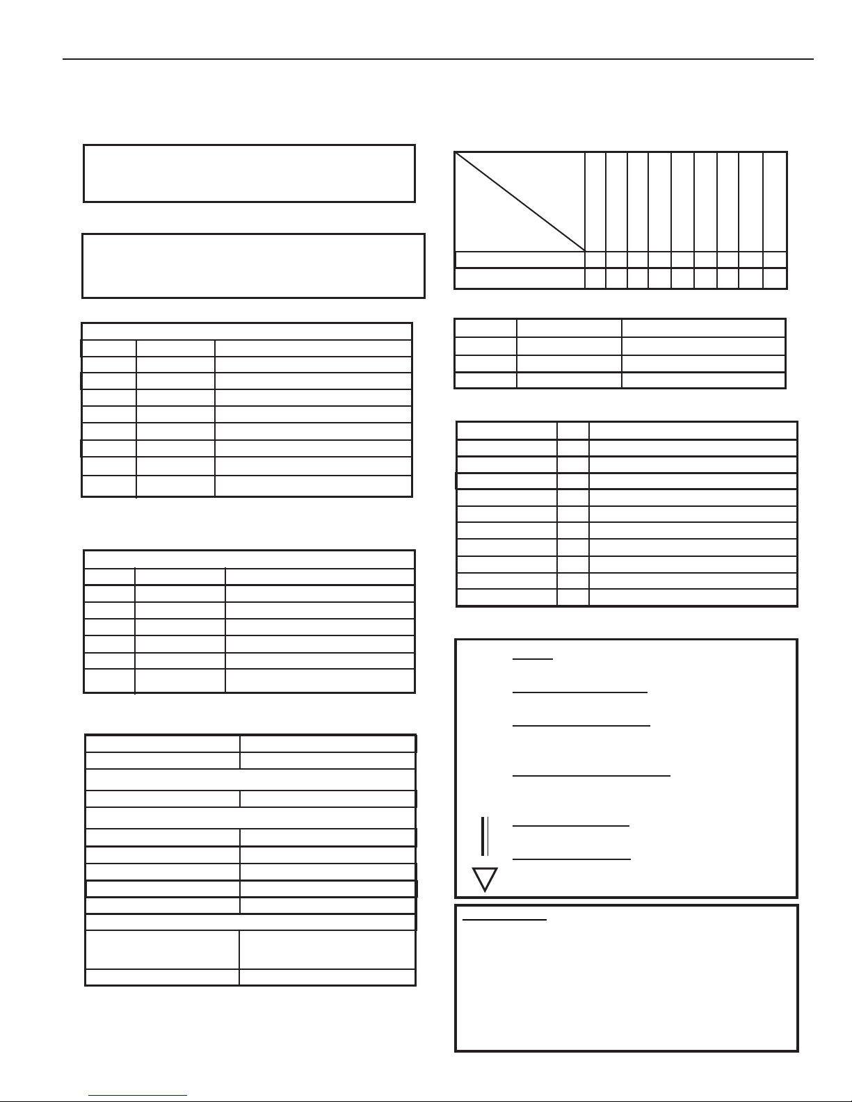
Item # Accessory
Color Applicability/Trim Level
Vehicle/Trim Color
yrosseccA
roloC
TOYOTA Camry 2012 - Keyless Entry System
Southeast Toyota Distributors, LLC 1 of 10

Page 2 of 10
TOYOTA CAMRY KEYLESS ENTRYSYSTEM
Negative Battery
REMOVETHEDRIVER'S SIDEKICKPANEL:
REMOVETHEDRIVER'SSIDESCUFFPLATE:
REMOVETHESIDEDASH PANEL:
INSTALLATION PREPARATION
Before starting installation
1. Familiarizeyourselfwiththe installation
instructions.
2. Inspectkitcomponents(Refertokit
contentsandhardware bagcontents).
VEHICLEPREPARATION
1. Placeprotectivecoveringsonvehicle.
2. "IMPORTANT........IMPORTANT"
Disconnect Negative Battery
Cable
1. Refer to the vehicle repair manual, and
carefullyremovefront kickpanel.
1. Refer to the vehicle repair manual, and
carefullyremovefrontscuffplate.
PLASTIC NUT
1. Refer to the vehicle repair manual, and
carefullyremovethedriver'sside dash finish
panel.
Southeast Toyota Distributors, LLC

Page 3 of 10
TOYOTA CAMRY KEYLESS ENTRYSYSTEM
REMOVETHELOWERFINISHPANEL:
1. Remove (1) 10mm bolt and (1) phillips screw
fromthedriver'ssidelower finish panel.
2. Disengage the hood release cable from the
hoodreleaselatch handle.
3.Carefullypullthelowerfinishpaneloutwardfrom
the vehicle dash to disengage the snap clips
holdingitplace,thensetthepanelaside where it
willnotbedamaged.
REMOVETHELOWER CRASH SHIELD:
1.Remove(4) 10mmboltsfromthe driver'slower
crashshield.
2. Place a protective cover on the driver's floor
area,and wrapthemetalcrashshieldwithacover
topreventscratching before movingittothe side.
PREPARING FOR INSTALLATION
REMOVETHESTEERINGWHEELSHROUD:
1. Remove the (2) phillip screws from the lower
steeringcolumncover.
2. Carefully dislodge the steering column cover
tabsand remove thelowercover.
ThisStep IsOptional
10mm BOLT PHILLIPS SCREW
HOODRELEASE
Southeast Toyota Distributors, LLC

MOUNTING MAIN CONTROL MODULE:
NOTE: Guide long cable through the module eyelets as shown.
DO NOT WRAP OR BUNDLE ANTENNA HARNESS. Module antenna wire must extend as
high up as possible and secured in place for best signal.
INSTALLATION PROCEDURES
MODULE PREPARATION
1. Secure the antenna to the back side
of the module, using a supplied foam
pad.
2. Route the antenna and secure to the
main harness with (2) cable ties.
Foam Pad
Cable Ties
"IMPORTANT........Failure to route the antenna cable as described will result in re-
duced range of the system.
Page 4 of 10
TOYOTA CAMRY KEYLESS ENTRY SYSTEM
1. Secure the module to the dash brace at the far left end to the left of the driver side JB, using the long
cable ties and adhesive pad provided in the hardware bag.
Before Mounting Module After Mounting Module
Southeast Toyota Distributors, LLC

IMPORTANT ! After installation, inspect & insure that all Keyless System
Harness are clear of all HOT, SHARP or MOVING objects
T-TAP INSTALLATION:
A. When installing female T - Tap connectors, be sure the wire is located inside the wire channel of the
female T - Tap connector before closing connector over the wire with pliers.
Step A Step B Step C
T - Tap Wire from main keyless
harness
Page 5 of 10
TOYOTA CAMRY KEYLESS ENTRY SYSTEM
1. Install the ON/OFF bezel and nut. Tighten
nut with care, do not over torque the nut.
2. Tie wrap to main harness loom in driver's
kick panel directly besides the A3 ground
lug as shown.
NOTE: Toggle switch must be in the
"OFF" position.
MOUNTING THE TOGGLE SWITCH:
INSTALLATION PROCEDURES
SECURING MODULE GROUND:
1. Secure the keyless entry system black
ground wire to the left hand 10mm bolt
securing the crash knee air bag.
2. Torque the 10mm bolt to 7ft. lbs.
S
1
2
4
3
Ground Location
Southeast Toyota Distributors, LLC
This Step is Optional
1. Remove (4) 10mm bolts from driver’s lower
crash shield.
2. Place a protective cover on the driver’s floor
area & wrap the metal crash shield with a cover
to prevent scratching before moving it to the side.
Note: If lower crash shield is removed the 4 bolts
must bere-installed and torqued at 7 ft. lbs
Use the torque sequence below.

WIRING DIAGRAM
Page 6 of 10
PINK[Driver's Lock Switch]:Usea blackT-Tapand
connecttothe RED **wirein connectorKI1,location
10.
PINK/WHITE [Driver'sUnlock Switch]: Useablack
T-Tapandconnect totheGREEN**wireinconnector
KI1,location11.
PINK/WHITE [Driver's Unlock Detect Switch]: Use
a black T-Tap and connect to the VIOLET wire in
connectorKI1,location 16.
WHITE [DriverDoorUnlock Motor -Towards Door
Lock] - (See Detail A)
BLUE/WHITE [Driver DoorUnlock Motor- Towards
Body ECU] - (See Detail A)
RED [+12VDC Battery]: Use a yellow T-Tap and
connect to the GREEN wire in connector I36,
location5.
YELLOW [ +12VDCAccessory]: Use a blue T-Tap
and connect to the BLACK wire in connector I36,
location6.
CHASSISGROUND- Connect thering terminal totheleft hand
10mmboltsecuring the driver's crashknee airbag.
GREEN/RED WIRE [Horn]: Use red T-Tap and connect to the
Lt. GREEN WIRE in connector I28, location 9.
WHITE WIRE [Tail Lights]: Use black T-Tap and connect to the
BLACK WIRE in connector I25, location 18.
2 Pin Molex Connector - Plug into Toggle Control
Switch.
DETAIL "A"
DRIVER'S DOOR UNLOCK CIRCUIT
Cut the GRAY WIRE in connector KI1, location 12.
Striptheinsulation from bothsides of thecut wire,
and crimp the WHITE WIRE from the keyless
harnessto theHARNESS sideof thecut wire.Crimp
the BLUE/WHITE WIRE from the keyless harness
to the CONNECTOR side of the cut wire.
Harness
Wires
BLUE w/
WHITE
Cut & Strip
Existing
Wire
WHITE
BLUE WIRE [Headlighs]: Use black T-Tap and connect to the
RED WIRE in connector I25, location 17.
WIRING DIAGRAM CAMRY
Southeast Toyota Distributors, LLC

2. CONNECTOR I28 : Horn
Location : Spiral Spring Connector Top Of Steering
Column
Pin 9
Lt. Green
Horn
Page 7 of 10
4. CONNECTOR I25 : Tailights
Location : Combination Switch Connector
Pin 18
Black
Tail Lights
CAR KEYLESS
Red Blue
Black White
1234
5678
1. CONNECTOR I36 : Ignition Switch
Location : Steering Column
12345678910
11 12 13 14 15 16 17 18 19 20
CAR KEYLESS
Lt.Green Green/Red
CAR KEYLESS
Green Red
Black Yellow
Pin 5
Green
+12V Battery
Pin 6
Black
+12V Accessory
Black Connector
Black Connector
Pin 17
Red
Head Lights
Pin 12
Gray Wire
Driver's Door Unlock
Motor
Pin 16
Violet Wire
Door Unlock Detect
Switch
CONNECTOR DETAILS: CAMRY
3. CONNECTOR KI1 : Door Locks
Location : Driver's kick panel area
CAR KEYLESS
Red Pink
Green Pink/White
Gray White&Blue/White
Violet Pink/White
Pin 10
Red Wire
Door Lock Switch
Pin 11
Green Wire
Door Unlock Switch
Southeast Toyota Distributors, LLC

COMPLETING THE INSTALLATION: CAMRY
TESTING THE SYSTEM:
1. Prior to delivering the vehicle, test all
features of the system accordinng to the
owner's manual included.
LOCK - Press and release the LOCK button
on the transmitter. All doors should lock,
headlights should come on.
UNLOCK - Press and release the UN-
LOCK button on the transmitter. The driver's
door should unlock, headlights should come
on.
Press and release the UNLOCK button
again. All doors should unlock.
Press and hold the PANIC button. The horn
should sound and the parkings lights should
flash.
Press and release the PANIC button to
silence the horn.
NOTE: Be sure to test both transmitter that
were included in the kit.
ASSEMBLE ALL REMOVED PANELS TO
THE VEHICLE:
1. Refer again to the vehicle repair manual
and reassemble all panels that were removed
for installation back onto the vehicle.Test
thoroughly, all mechanical components
disconnected and or removed from the
vehicle during the installation of this
accessory.
PREPARING THE VEHICLE FOR DELIVERY:
1. To set the arm/disarm chirps to "soft"
chirps.
2. Start with the doors in the unlocked
position, Toggle Control Switch in the "OFF"
position.
3. Turn the ignition key to the on position.
4. Turn the ignition key off, then immediately
switch the Toggle Control Switch "ON" then
"OFF" 4 times.
5. The vehicle horn should respond with soft
horn chirps.
6. Place the Owner’s Card in glove box.
Page 8 of 10
Southeast Toyota Distributors, LLC
Torque the negative battery cable to 48” lbs.

STEP 2
PROGRAMMINGNEWor REPLACEMENTTRANSMITTERS TOTHESECURITYMODULE:
IMPORTANT NOTE : Once you enter the programming mode, if 15 seconds elapse with no activity on the
system, the programming mode will be terminated. If this happens, simply start over.
STEP 1
Turn the vehicle’s ignition key
ON then OFF 7 times.....
....Ending in the OFF position.
Toget started,enter thevehicle andclose alldoors,
then lock the doors by using the door lock switch
mounted on the driver’s door panel.
STEP 3
Press and Hold the Lock button on the transmitter
until the Driver’s Door Unlocks.
STEP 4
Lock all doors by using the door lock switch
mounted on the driver’s door panel.
STEP 5
Repeat Steps 3 and 4 for all transmitters that you
need to program to operate the vehicle.
(Maximum of 4 transmitters per vehicle)
STEP 6
When all transmitters have
been programmed, turn the
ignition key ON then OFF to
exit the program mode.
COMPLETING THE INSTALLATION: CAMRY
Page 9 of 10
Southeast Toyota Distributors, LLC

VEHICLE FUNCTION CHECKLIST
THESEPOINTSMUSTBECHECKEDTOENSUREAQUALITYINSTALLATION
Head Light
High Beams
Turn Signal Lights
Tail Lights
StopLights
BackupLights
Hazard Lights
Marker Lights
Dome/CourtesyLights
Panel/Switch Illumination
AccessoryControls/Illumination
(if equipped)
Rear Window Defogger
(if equipped)
Key Sensor Buzzer
Fog Lights (if equipped)
Day Time Running Lights
(if equipped)
Trunk/Tailgate/Bed Lights
(if equipped)
Glove Box Light (if equipped)
ABS Light (if equipped)
Rear Wiper/Washer
(if equipped)
Clock (if equipped)
Accessory Power Socket
(if equipped)
Starter
Audio/Video (if equipped)
Power Sliding Door
(if equipped)
If the warning lights remains on, it may
indicate a system malfunction.
Convenience Memory Settings
(if equipped)
Heated Seats (if equipped)
Massage Seats (if equipped)
Power Side Mirrors (if equipped)
Side Mirror Defogger (if equipped)
Front Windshield Defogger (if equipped)
Navigation System (if equipped)
Rear Sunshade (if equipped)
Cruise Control Light (if equipped)
Steering Wheel Audio Control
(if equipped)
HVAC
Power Locks (if equipped)
Power Windows (if equipped)
Gauges
Front Wiper/Washer
Hood Latch Release
Passenger Air Bag Switch (if equipped)
Rollover Side Curtain Air Bag Switch (RSCA)
Horn
Seat Belt Warning Light
Air Bag Warning Light
Lamp Failure Sensor
Track/Skid Control Light (if equipped)
If the warning lights remains on, it may
indicate a system malfunction.
If the warning lights remains on, it may
indicate a system malfunction.
If the warning lights remains on, it may
indicate a system malfunction.
If the warning lights remains on, it may
indicate a system malfunction.
TOYOTA CAMRY KEYLESS ENTRYSYSTEM
Tire Pressure Monitoring System (TPMS)
PriortoTPMS activation and Pre-Delivery
Service (PDS) of the vehicle the TPMS light will
blink when IG is turned on. After TPMS activa-
tion and PDS of the vehicle the TPMS light will
illuminate for a few seconds and go off when IG
is turned on.
Page 10 of 10
Southeast Toyota Distributors, LLC
This manual suits for next models
1
Table of contents
Other Toyota Remote Starter manuals

Toyota
Toyota PT398-42130 Configuration guide

Toyota
Toyota PT398-60080 User manual

Toyota
Toyota RS3200 PLUS User manual

Toyota
Toyota 2008 SEQUOIA User manual

Toyota
Toyota PT398-02080 User manual

Toyota
Toyota TVIP V4 User manual

Toyota
Toyota PT398-00100 User manual

Toyota
Toyota PT398-47091 User manual

Toyota
Toyota TVIP V4 User manual
Popular Remote Starter manuals by other brands

Sealey
Sealey ROADSTART instructions

VOLTCRAFT
VOLTCRAFT 2369285 operating instructions

Gallo Tech
Gallo Tech GTStarter-2 GTS-2 Operation & installation manual

CrimeStopper
CrimeStopper RS-901.III installation instructions

Prestige
Prestige SS6900 installation manual

AutoLoc
AutoLoc KL550 User guide and installation manual