Toyota PT398-02080 User manual

TOYOTA COROLLA 2010– TVIP V4
PREPARATION REMOTE ENGINE STARTER (RES)
Page 1 of 46
Issue: A 03/12/10
Part #: PT398-02080 or PT398-02100
NOTE: Part number of this accessory may not be the same as the part number shown.
Conicts: Do not install into Manual Transmission Vehicles or Vehicles without RKE systems.
RecommendedTools
Personal&VehicleProtection Description
Safety Glasses
Safety Gloves (Optional
Vehicle Protection Blankets, Parts Boxes
SpecialTools
Cable Wire Routing Tool
InstallationTools
Screwdriver #2 Phillips, Phillips Jewelers, Flat Blade Jewelers
Nylon Panel Removal Tool e.g. Panel Pry Tool #1 Toyota SST# 00002-06001-01
Side Cutters
Torque Wrench 36 in•lbf (4.07 N•m); 66.4 in•lbf (7.5 N•m);
70.8 in•lbf (8.0 N•m)
Utility Knife
Tape Clear, Electrical
Socket 10mm, extension
Pliers Needle Nose, Pliers
SpecialChemicals
Cleaner
Glass Cleaner
x1
x1
x2 x1
x1
x40
x2
x1
x1
x1
x1
x1
x1
x3
Spanish x2
Spanish x1
Spanish x2
Spanish x2
x1
English x2
English x1
English x2
English x2
AdditionalItems
(may be required)
Item# Description
RecommendedSequence
ofApplication
Item# Description
1TVIP V5 System
2TVIP V4 System
RES ECU
RES Harness
Harness Clamp Hood Switch
RES ECU Bracket
Wire Tie
Hood Switch
Screw
Remote Label
Window Label
Owners Guide
Gateway ECU
Hood switch
Harness
Scotch Lock
Butyl Tape
Gateway ECU
Bracket
Foam Tape
M6 Screw
Key Tag
Engine Room
Label

TOYOTA COROLLA 2010– TVIP V4
PREPARATION REMOTE ENGINE STARTER (RES)
Page 2 of 46
Issue: A 03/12/10
TableofContents
PreparationI. ............................................................................................................................ 1–3
Table of Contents1. ................................................................................................................................................2
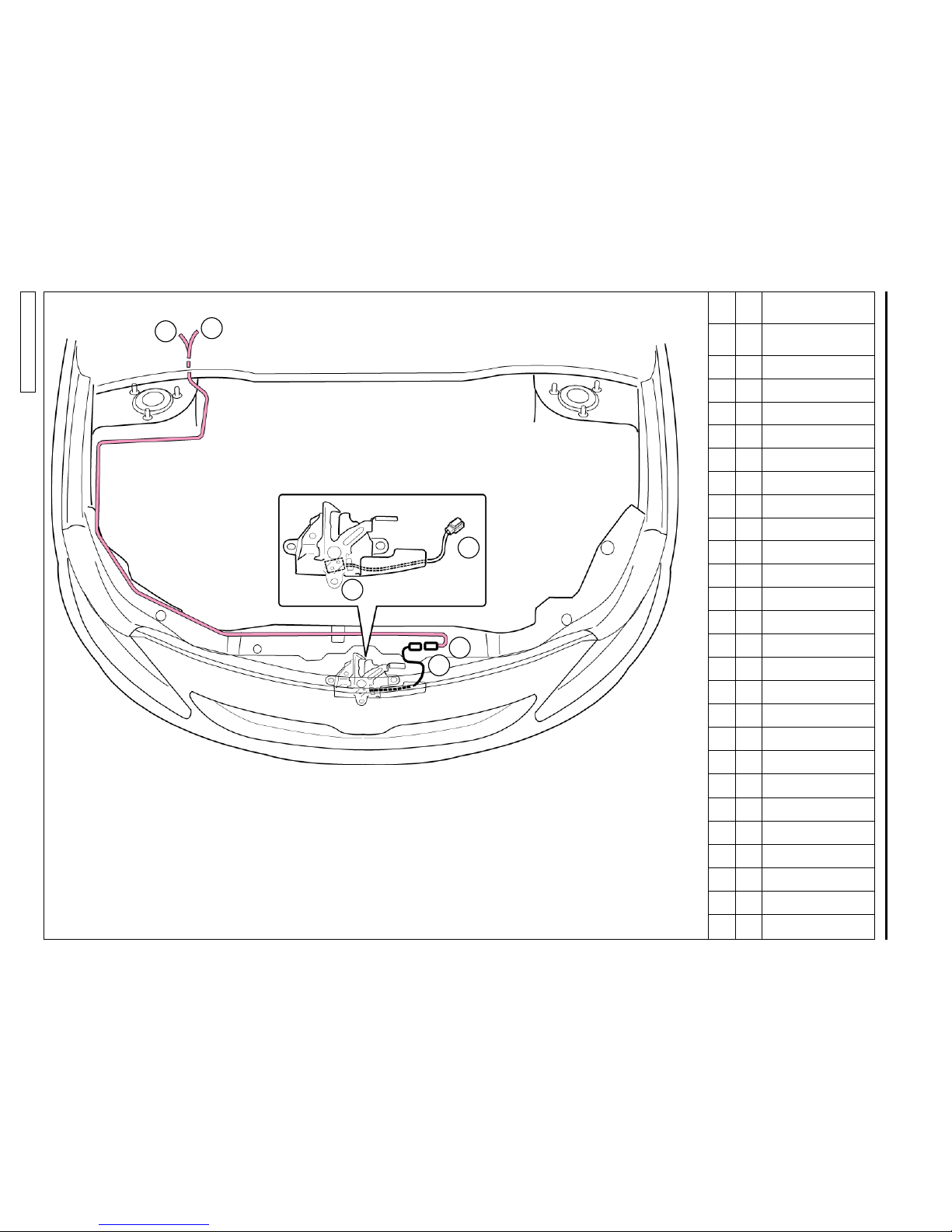
Wire Routing Overview2. .................................................................................................................................. 3–4
ProcedureII. ............................................................................................................................5–37
Disassembly (Engine Compartment)1. ..................................................................................................................6
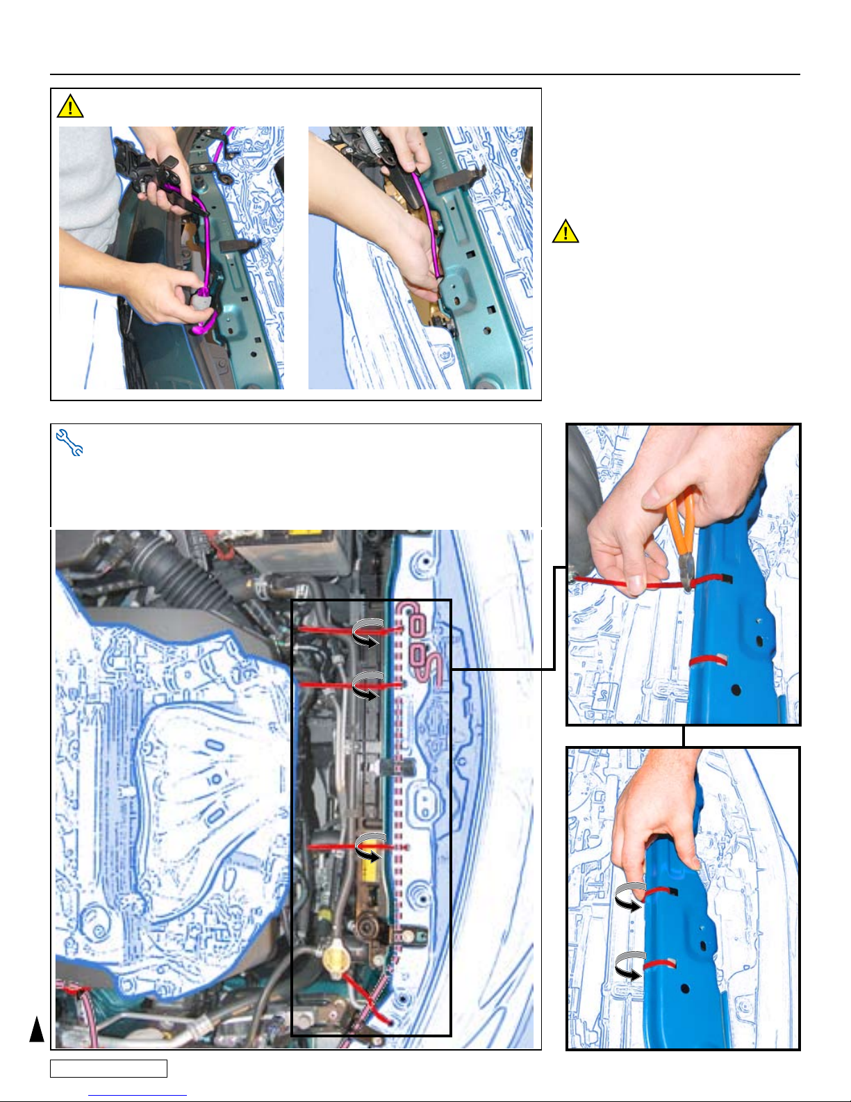
Hood Switch Installation2. ......................................................................................................................................6
Disassembly (Passengers Area)3. ....................................................................................................................... 11
V4 Wire Harness Installation (Driver’s Side)4. .....................................................................................................16
V4 Wire Harness Installation (IP Panel)5. ............................................................................................................20
V4 Wire Harness Installation (Steering Column)6. ..............................................................................................21
V4 Wire Harness Installation (Passengers Side)7. ..............................................................................................22
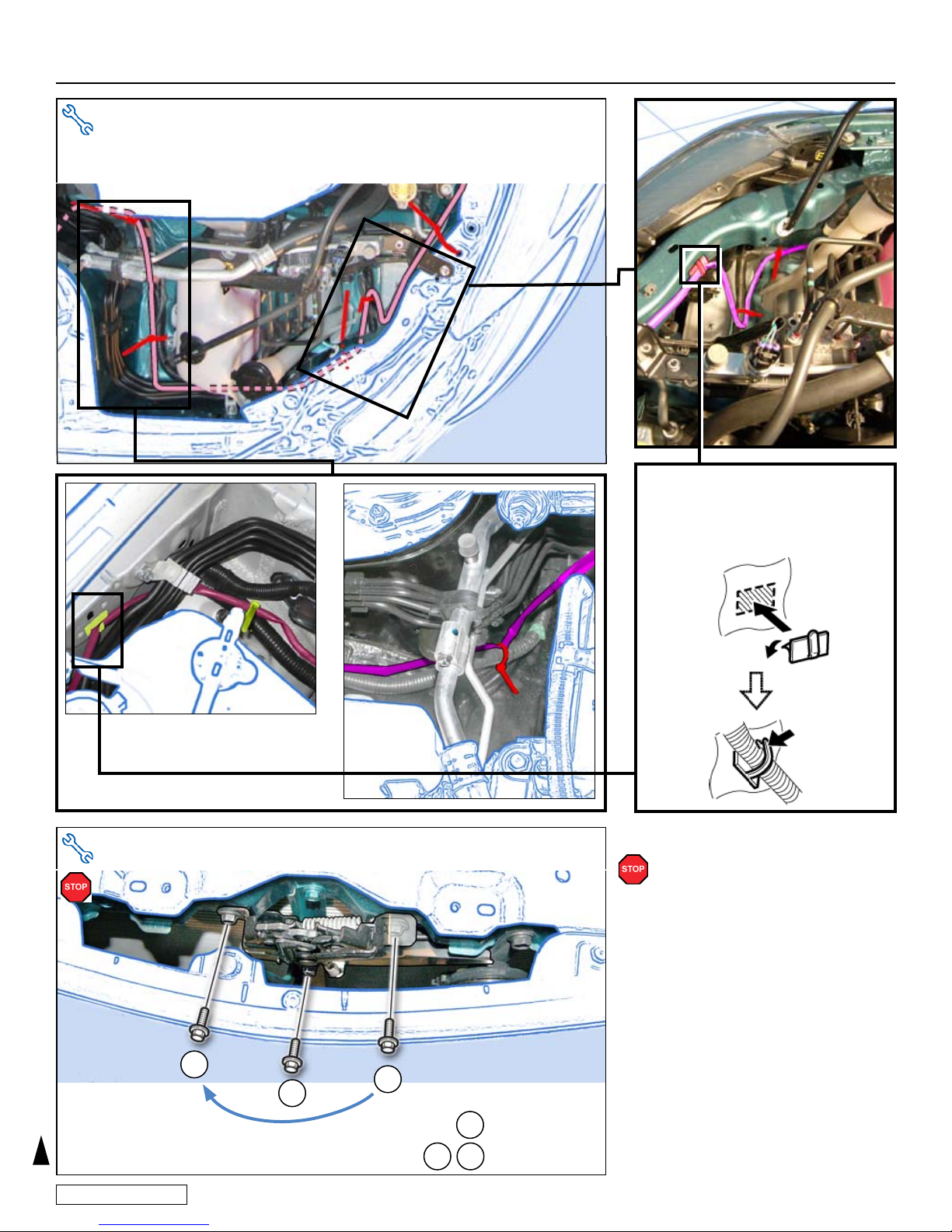
Hood Switch Harness Routing (Continued)8. ......................................................................................................23
RES ECU and Gateway ECU Preparation9. .......................................................................................................26
V4 Harness Installation (Glovebox Area)10. ..........................................................................................................26
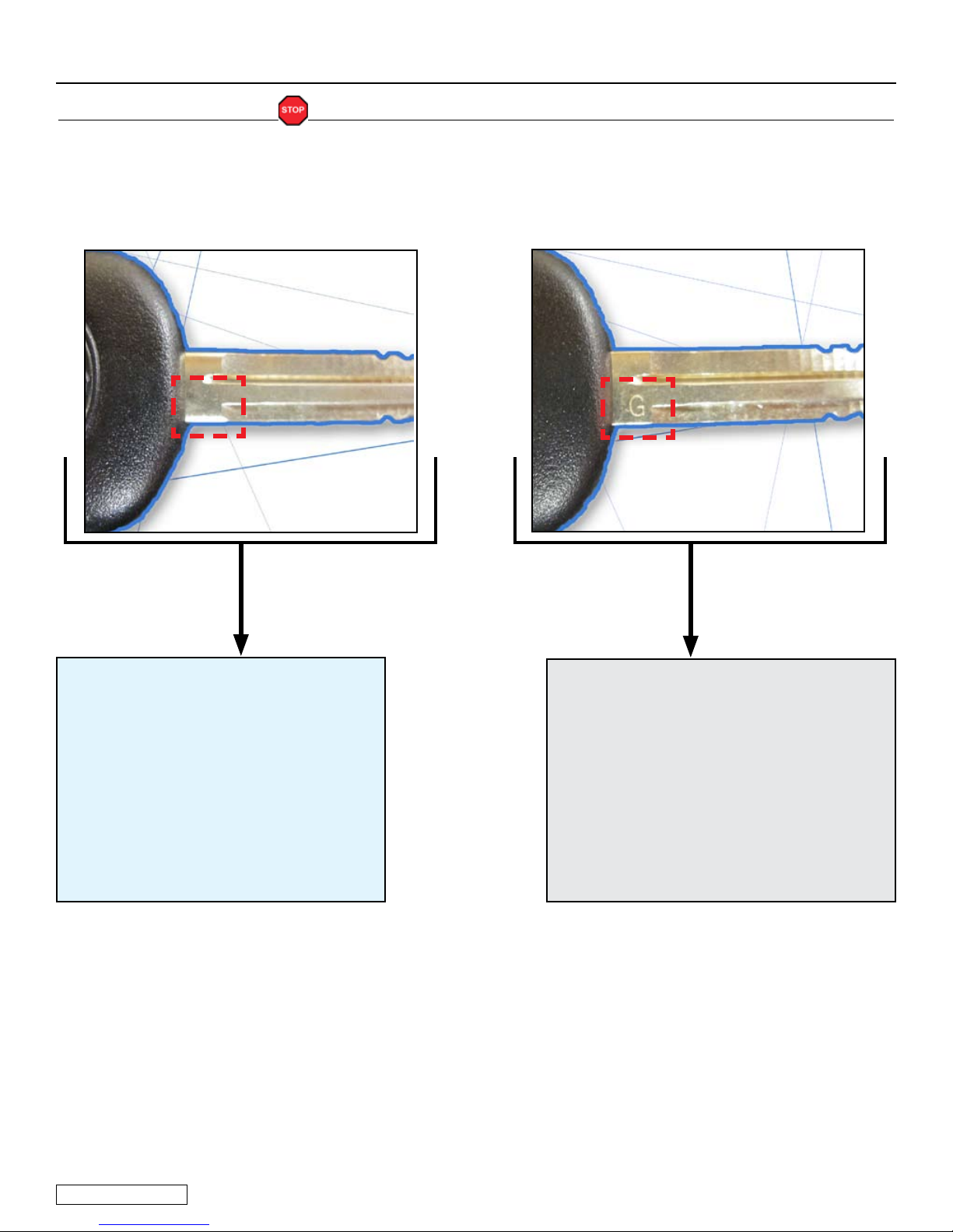
Hood Switch Pin11. ................................................................................................................................................27
V4 Harness Installation (Continued)12. .................................................................................................................29
Registration Preparation13. ...................................................................................................................................32
Phase 314. Registration.........................................................................................................................................34
Phase 4 Registration15. .........................................................................................................................................38
Tags and Labels16. ................................................................................................................................................42
Completing the Installation17. ................................................................................................................................43
ChecklistIII. ........................................................................................................................... 44–46
Accessory Function Checks1. ..............................................................................................................................44
Vehicle Function Checks2. ...................................................................................................................................45
Legend
Do not proceed until process
has been completed.
Follow steps carefully to
avoid damaging the Vehicle
or Accessory
Use caution to avoid injury.
Used in Figures to call attention
to specic tools recommended
for the process.
Highlights a change in
installation with respect to
previous issue.
Indicates that torque is related
to safety.
Video available; click to play.
AccessoryInstallationPractice(readbeforeinstallation)
Care must be taken when installing this accessory to ensure damage does not
occur to the vehicle. The installation of this accessory should follow approved
guidelines to ensure a quality installation.
These guidelines can be found in the “Accessory Installation Practices”
document.
This document covers such items as:
Vehicle Protection (use of•
covers and blankets, cleaning chemicals, etc.)
Safety (eye protection, checking torque procedure, etc.)•
Vehicle Disassembly/Reassembly (panel removal, part storage, etc.)•
Electrical Component Disassembly/Reassembly (battery disconnection,•
connector removal, etc.)
Please see your Toyota dealer for a copy of this document.

TOYOTA COROLLA 2010– TVIP V4
PREPARATION REMOTE ENGINE STARTER (RES)
Page 3 of 46
Issue: A 03/12/10
TVIP Vehicle Description
A 2D 14P WHITE
B – WIRE TERMINAL
(Not Used)
CE46 WIRE TERMINAL
(Red Wire)
D – WHITE TAPE
E – FUSE
F – RELAY
GE4 8P WHITE
H – RES ECU
I – 20P WHITE
(for RES ECU)
J – 8P WHITE
(for RES ECU)
K – WIRE TERMINAL
(Green/Red Wire)
L – WIRE TERMINAL
(White/Black Wire)
M – 2P WHITE
(for Hood Switch)
N – Gateway ECU
O – 5P WHITE
(for Gateway ECU)
P E92 2P WHITE
(Male)
Q – 1P WHITE
(for Registration)
R EM3 13P WHITE
A
B
D
F
EG
C
J
I
P
N
O
K
L
M
Q
R
H
WireHarnessOutline(PassengersCompartment)

TOYOTA COROLLA 2010– TVIP V4
PREPARATION REMOTE ENGINE STARTER (RES)
Page 4 of 46
Issue: A 03/12/10
J – WIRE TERMINAL
(Green/Red Wire)
K – WIRE TERMINAL
(White/Black Wire)
S – Hood Switch
T – 2P BLACK
U – 2P WHITE
T
K
S
L
T
U
WireHarnessOutline(EngineCompartment)

TOYOTA COROLLA 2010– TVIP V4
PROCEDURE REMOTE ENGINE STARTER (RES)
Page 5 of 46
Issue: A 03/12/10
ConrmtheVehicle’sKey:
NOTE: There are 2 different Kits and Registration Procedures that can be identied by
looking at the Vehicle’s Key.
IftheVehicle’sKeydoesnothave
“G”onit
1.YoucanuseKitPN:PT398-02080or
PT398-02100
2.YouMUSTUsethePhase3Registra-
tion.(seeregistrationsectionpg.33)
IftheVehicle’sKeyhas“G”engraved
onit:
1.YouMUSTuseKitPN:PT398-02100
2.YouMUSTUsethePhase4Registra-
tion.(seeregistrationsectionpg.33)

TOYOTA COROLLA 2010– TVIP V4
PROCEDURE REMOTE ENGINE STARTER (RES)
Page 6 of 46
Issue: A 03/12/10
Disassembly.1)
(EngineCompartment)
Place the Vehicle in Park witha)
the Parking Brake set.
Disconnected the Negativeb)
Battery Terminal.
Protect the Fender.•
Note the Battery Cable Position•
as it will be re-installed in the
same position.
CAUTION:Do not touch the
Positive Terminal.
ForBoltonEngineCovers
Remove the Engine Cover.c)
Remove 2 Nuts.•
ForCliponEngineCovers
Remove the Engine Cover.d)
Pull up on the Engine Cover eas-•
ing the Rubber Grommets off of
the Metal Studs on the Engine.
Dislodge the Relay block.e)
Press in on the clip and slide it off•
its Bracket.
10mm Socket Fig. 1-1
10mm Socket Fig. 1-2
10mm Socket Fig. 1-3

TOYOTA COROLLA 2010– TVIP V4
PROCEDURE REMOTE ENGINE STARTER (RES)
Page 7 of 46
Issue: A 03/12/10
2) HoodSwitchInstallation.
Dislodge the Hood Locka)
Assembly.
Remove 3 Bolts.•
Remove the Hood Lockb)
Cable from the Hood Lock.
Release the Spring from thec)
Hood Lock.
Cut the Harness Clamp fromd)
the Hood Switch Harness.
Make sure to hold the Hood
Switch by the its sides. If the
Hood Switch is broken RES will
not function.
Side Cutters Fig. 2-3
Needle Nose Pliers Fig. 2-2
10mm Socket Fig. 2-1

TOYOTA COROLLA 2010– TVIP V4
PROCEDURE REMOTE ENGINE STARTER (RES)
Page 8 of 46
Issue: A 03/12/10
Install thee) Hood Switch with
the Switch Lever underneath
the Hood Lock Trigger Lever.
Make sure the Hood Switch Lever
is positioned properly. If the Hood
Switch is Broken RES will not
function.
Route the Hood Switchf)
Harness as shown.
Reinstall the Spring.g)
CAUTION: Make sure that the
Spring seats properly.
Needle Nose Pliers Fig. 2-5
Phillips Jewelers Screwdriver Fig. 2-4
Route the Hood Switchh)
Harness below the Radiator
Reinforcement Brace.
Fig. 1-6Fig. 2-6

TOYOTA COROLLA 2010– TVIP V4
PROCEDURE REMOTE ENGINE STARTER (RES)
Page 9 of 46
Issue: A 03/12/10
i) Connect the 2P Hood Switch
Connector to the 2P Hood
Switch Harness Connector.
Place the 2P Connectorsj)
and Wire Harness Under
the Radiator Reinforcement
Brace.
CAUTION: Wrap the Hood Latch
in a small blanket before
continuing with the Hood Switch
Harness routing.
Fig. 2-7
Side Cutters Fig. 2-8
k) Route and Secure the Hood Switch Harness as shown.
(3 Wire Ties)
When installing the Wire Ties be sure• to rotate their Rachet End under the
Radiator Reinforcement Brace as shown.

TOYOTA COROLLA 2010– TVIP V4
PROCEDURE REMOTE ENGINE STARTER (RES)
Page 10 of 46
Issue: A 03/12/10
66.4 in•lbf (7.5 N•m) •
70.8 • in•lbf (8.0 N•m)
3
2
1
1
2
3
T
I
G
H
T
E
N
Torque Wrench Fig. 2-10
Side Cutters Fig. 2-9
l) Route and secure the Hood Switch Harness as shown. (4 Wire Ties
and 2 Harness Clamps)
Reinstall the Hood Lock.m)
Make sure to Torque the Bolts.
NOTE: Clean the mounting
surface with VDC approvided
Cleaner and Cleaning Method.

TOYOTA COROLLA 2010– TVIP V4
PROCEDURE REMOTE ENGINE STARTER (RES)
Page 11 of 46
Issue: A 03/12/10
1 Glovebox Under Cover
(if equipped)
2PS Step Cover
3PS Cowl Cover
4Glovebox
5DS Lower Dash Cover
6Lower Steering Column
Cover
7Lower Dash Brace
8Left Hand Lower Dash
Cover
9Center Console Lower Trim
10 Center Console Upper Trim
11 IP Panel Trim
12 IP Panel
Disconnect all Corresponding
Connectors
DisassemblyOverview
3) Disassembly
(Passenger’sArea)
Remove the Glove Boxa)
Under Panel. (if equipped)
Protect the Vehicle’s Interior.•
Fig. 3-1
PASSENGERS SIDE
DRIVERS SIDE
1
3
4
10
9
12
11
6
8
75
2

TOYOTA COROLLA 2010– TVIP V4
PROCEDURE REMOTE ENGINE STARTER (RES)
Page 12 of 46
Issue: A 03/12/10
Remove the Passenger’s b)
Step Cover.
Remove the Passenger’s c)
Cowl Cover.
Disconnect the Dampenerd)
from the Glove Box.
Remove the Glove Box.e)
Fig. 3-4
Nylon Panel Removal Tool Fig. 3-2
Nylon Panel Removal Tool Fig. 3-3

TOYOTA COROLLA 2010– TVIP V4
PROCEDURE REMOTE ENGINE STARTER (RES)
Page 13 of 46
Issue: A 03/12/10
Remove the Lower Dash.f)
Release the Steeringg)
Columns Tilt and
Telescope Lock.
Dislodge the Center Clip.h)
Insert ngers into the opening of •
the Tilt Lever of the Steering Col-
umn Under Cover to disengage
1 Claw.
CAUTION: Do not force this clip
as it is very easy to break.
Nylon Panel Removal Tool Fig. 3-5
Fig. 3-6
Dislodge the Back Clips oni)
both sides.
Release the Front Clips onj)
both sides.
Insert the Key into the Ignition and•
turn it to ON.
Turn the Steering wheel from•
Right to Left to access the Holes.
Use a Flat Blade Jewelers•
Screwdriver wrapped with
Electrical Tape to release
the clips.
Remove the Key from the Ignition.•
Nylon Panel Removal Tool, Flat Blade Jewelers Screwdriver,
Electrical Tape Fig. 3-7

TOYOTA COROLLA 2010– TVIP V4
PROCEDURE REMOTE ENGINE STARTER (RES)
Page 14 of 46
Issue: A 03/12/10
Remove the Lower Dashk)
Brace.
Remove 2 Nuts.•
Disconnect the Vehicle Harness•
Clip from the Brace.
CAUTION: Sharp metal edges.
Remove the Left Hand Lowerl)
Dash Panel.
Nylon Panel Removal Tool Fig. 3-9
10mm Socket, Pliers Fig. 3-8
Remove the Centerm)
Console’s Left Lower Trim.
Nylon Panel Removal Tool Fig. 3-10

TOYOTA COROLLA 2010– TVIP V4
PROCEDURE REMOTE ENGINE STARTER (RES)
Page 15 of 46
Issue: A 03/12/10
Remove the IP Panel’s Trim.p)
Remove the Centero)
Console’s Left Upper Trim.
Nylon Panel Removal Tool Fig. 3-12
Nylon Panel Removal Tool Fig. 3-13
Nylon Panel Removal Tool Fig. 3-11
Use Masking tape to protectn)
the Dash.

TOYOTA COROLLA 2010– TVIP V4
PROCEDURE REMOTE ENGINE STARTER (RES)
Page 16 of 46
Issue: A 03/12/10
4) V4HarnessInstallation.
(Driver’sSide)
Locate the Vehicle Harnessa)
Clamp below the Steering
column on the Drivers Side.
Secure the White Tapeb)
Marker to the Vehicle
Harness with 1 Wire Tie.
Secure the V4 Harness and c)
its Relay to the Vehicle
Harness with 1 Wire Tie.
Remove 2 Screw from the IPq)
Panel.
Remove the IP Panel.r)
Phillips Screwdriver Fig. 3-14
White Tape Marker

TOYOTA COROLLA 2010– TVIP V4
PROCEDURE REMOTE ENGINE STARTER (RES)
Page 17 of 46
Issue: A 03/12/10
Disconnect the Vehicle 14P f)
Connector from the Driver’s
Side Junction Box.
V4ONLY
Route the two 14P V4 d)
Connectors toward the
Driver’s Side Junction Block.
Secure the V4 Harness e)
to the Vehicle Harness with
1 Wire Tie.

TOYOTA COROLLA 2010– TVIP V4
PROCEDURE REMOTE ENGINE STARTER (RES)
Page 18 of 46
Issue: A 03/12/10
Disconnect the Vehicle 14P k)
Connector from the V5
Connector.
V4 /V5ADDONONLY
Cut the Wire Tie securing thei)
V5 14P Connector.
Cut the Wire Tie securing thej)
V5 Harness to the Vehicle
Harness.
Plug the V4 14P Connectors g)
in between the Vehicle
Connector and the
Junction Box.
Secure the Connectors toh)
the Vehicle Harness with
1 Wire Tie.

TOYOTA COROLLA 2010– TVIP V4
PROCEDURE REMOTE ENGINE STARTER (RES)
Page 19 of 46
Issue: A 03/12/10
Secure the V4 and V5 14P o)
Connectors to the Vehicle
Harness with 1 Wire Tie.
Secure the V4 and V5 p)
Harnesses to the Vehicle
Brace with 1 Wire Tie.
Connect the Vehicle 14P n)
Connector to the V4 14P
Connector.
Route the two V4 14P l)
Connectors towards the
Driver’s Side Junction Box.
Connect the V4 14P m)
Connector to the V5 14P
Connector.

TOYOTA COROLLA 2010– TVIP V4
PROCEDURE REMOTE ENGINE STARTER (RES)
Page 20 of 46
Issue: A 03/12/10
5) V4HarnessInstallation.
(IPPanel)
GO BACK to the White Tape
Marker
Route the Red Wire upwarda)
as shown.
Secure the Red Wire andb)
the Bundled up Black Wire
to the Vehicle Harness with
1 Wire Tie.
Route the Red Wire andc)
secure it with 1 Wire Tie.
This manual suits for next models
1
Table of contents
Other Toyota Remote Starter manuals

Toyota
Toyota PT398-60080 User manual

Toyota
Toyota 2008 SEQUOIA User manual

Toyota
Toyota TVIP V4 User manual

Toyota
Toyota PT398-42130 Configuration guide

Toyota
Toyota 00016-32901 User manual

Toyota
Toyota PT398-00100 User manual

Toyota
Toyota TVIP V4 User manual

Toyota
Toyota RS3200 PLUS User manual

Toyota
Toyota PT398-47091 User manual
Popular Remote Starter manuals by other brands

Clifford
Clifford Responder LE 3.3X installation guide

Excalibur
Excalibur AL-1950-EDPB Operation guide

Omega Research & Development
Omega Research & Development Excalibur Quick start operation guide

Schumacher
Schumacher Instant Power XP2260 owner's manual

HID
HID MiniProx 5365H Series Installation

Absaar
Absaar AB-MJS150 operating instructions