Toyota 86180-0W030 User manual

TOYOTA SOLARA 2006 - XM SATELLITE RADIO TUNER
Section I – Installation Preparation
Issue Page 1 of 12 pages DIO
Issue: B 02/13/06
Part Number: Tuner Assy 86180-0W030
Mounting Kit PT546-06060
Tuner Assy Kit Contents (86180-0W030)
Item # Quantity Reqd. Description
1 1 Satellite Tuner
Mounting Kit Contents (PT546-06060)
Item # Quantity Reqd. Description
1 Tuner Cable
3CUSHION TAPE
(100mm x 50mm)
2
12 LOCK TIE A (AVC-LAN)
2Bracket Ass’y SDARS
Receiver
2 NUT (M6)
3
4Screw (M5L8 )
1 ANTENNA
1 GOUND PLATE
1 CORRUGATED TUBE
4NYLON TAPE
(30mm x 30mm)
4
3CUSHION TAPE
(100mm x 50mm)
Hardware Bag Contents – 1
Item # Quantity Reqd. Description
1 3 CUSHION TAPE A
(100mm x 50mm)
2 12 LOCK TIE A (AVC-LAN)
Hardware Bag Contents – 2
Item # Quantity Reqd. Description
1 2 Tuner Bracket
2 2 NUT (M6)
3 4 Screw (M5L8 )
Hardware Bag Contents - 3
Item # Quantity Reqd. Description
1 1 Antenna
2 1 GOUND PLATE
3 1 CORRUGATED TUBE
4 4 NYLON TAPE
(30mm x 30mm)
5 3 CUSHION TAPE B
(100mm x 50mm)
Additional Items Required For Installation
Item # Quantity Reqd. Description
Conflicts
Note:
Recommended Tools
Safety Tools
Safety Goggles
Seat Covers
Floor Protectors
Special Tools
None
Installation Tools
Ratchet
Extension
Socket 10mm, 12mm
Phillips Screwdriver
Nylon Removal Tool
Masking tape (50 mm wide)
Torque Wrench 4.1 N·m
Side Cutter
Special Chemicals
Cleaner 3MTM Prepsol-70
General Applicability
Note:-
Recommended Sequence of Application
Item # Accessory
1
2
* Mandatory
Legend
STOP: Damage to the vehicle may occur. Do not
proceed until process has been complied with.
OPERATOR SAFETY: Use caution to avoid risk of
injury.
CAUTION: A process that must be carefully observed
in order to reduce the risk of damage to the
accessory/vehicle and to ensure a quality installation.
TOOLS & EQUIPMENT: Used in Figures calls out the
specific tools and equipment recommended for this
process.

TOYOTA SOLARA 2006 - XM SATELLITE RADIO TUNER
Section I – Installation Preparation
Issue Page 2 of 12 pages DIO
Issue: B 02/13/06
Parts Description of mounting Kit (PT546-06060)
Item # Parts Name
Q
t
y
A Tuner Cable 1
B CUSHION TAPE A
(
100mm x 50mm
)
3
2
C LOCK TIE A
(
AVC-LAN
)
12
A Bracket Ass’
y
SDARS Receive
r
2
B
N
UT
(
M6
)
2
3
C Screw
(
M5 x L8
)
4
A ANTENNA 1
B GOUND PLATE 1
C CORRUGATED TUBE 1
D
N
YLON TAPE
(
30mm x 30mm
)
4
4
E CUSHION TAPE B
(
100mm x 50mm
)
3
I
t
e
m
#
P
a
r
ts Na
m
e Parts No. Qty
1
Tuner
86180-0W030
1
Parts Description of Tuner Assy (86180-0W030)

TOYOTA SOLARA 2006 - XM SATELLITE RADIO TUNER
Section II – Installation Procedure
Issue Page 3 of 12 pages DIO
Issue: B 02/13/06
Section II – Installation Procedure
A. Vehicle Disassembly.
1. Set parking brake.
2. Shift into neutral (N), and then unscrew the
shift knob.
3. Remove the negative (–) battery cable.
(Figure A1):
i. Protect the fender before removing the
battery cable.
ii. Be careful not to touch the positive
terminal.
4. Remove the trim cover in the luggage
compartment. (Figure A2)
5. Disassemble the rear seat as follows:
i. Fold down the seatback, and then fold back
the cover to locate the bolts.
ii. Unbolt and remove the right rear seatback.
(Figure A3)
iii. Disengage the hooks and remove the rear
seat cushion and the rear seat hinge.
(Figure A4)
NOTE: Be careful not to damage the seat, door and
other vehicle parts when removing the seat
from the vehicle.
STOP
STOP
N
egative
b
atter
y
cable
Figure A1
10 mm Socke
t
Ratchet Extension
Screw
Cli
p
s x 2
Phillips screwdrive
r
Figure A2
Bolts x 2
12 mm Socke
t
Ratchet Extension
Figure A3
STOP
Fig. A-4
Rear Seat Hinge
Hooks x 2
Locating Tang

TOYOTA SOLARA 2006 - XM SATELLITE RADIO TUNER
Section II – Installation Procedure
Issue Page 4 of 12 pages DIO
Issue: B 02/13/06
6. Disengage the clips and claws and remove the
passenger side door scuff plate. (Figure A5)
7. Remove the passenger side cowl side trim as
follows (Figure A6):
i. Remove cap A.
ii. Disengage clip B and remove the cowl side
trim.
8. Remove the passenger side quarter trim panel
as follows (Figure A7)
i. Disengage the clips and remove the quarter
trim panel.
9. Remove the upper console panel.
i. Open the front and rear console box lids.
ii. Disengage the clips and remove the upper
console panel. (Figure A8)
Clips x 5
Claws x 4
Figure A5
N
ylon Removal Tool
Clips x 8
U
pp
er console
p
anel
Figure A8
N
ylon Removal Tool
Clip B
Cap A
Passen
g
er doo
r
N
ylon Removal Tool
Figure A6
Cli
p
s x 9
Figure A7
N
ylon Removal Tool

TOYOTA SOLARA 2006 - XM SATELLITE RADIO TUNER
Section II – Installation Procedure
Issue Page 5 of 12 pages DIO
Issue: B 02/13/06
10. Remove the front console box.
i. Disengage the clips, and then remove the
front console box. (Figure A9)
ii. Disconnect the connectors.
11. Remove the instrument cluster upper finish.
i. Place masking tape to protect the surface
trim.
ii. Insert the nylon removal tool at the side
edge of the upper panel to disengage the
clips, and then slide the upper panel toward
the rear of the vehicle to remove it.
(Figure A10)
iii. Disconnect the connectors.
12. Remove the instrument cluster finish panel
lower and head unit.
i. Remove the four (4) bolts, and then pull
the instrument cluster lower finish panel
toward you to remove the head unit.
(Figure A11)
ii. Disconnect the connectors.
NOTE: The removal procedure is the same for non-
navigation head units.
13. Remove the glove compartment door.
i. Disconnect the damper from the right end
of the glove compartment box.
(Figure A12)
Clips x 4
Front
console box
Figure A9
N
ylon Removal Tool
Bolts x 4
Clips x 4
Figure A11
N
ylon Removal Tool
10 mm Socke
t
Screw
Damper
Figure A12 Phillips screwdrive
r
Guide pins x 3
Insert
tool
here
Cli
p
s x 5
Figure A10
Masking tape
N
ylon Removal Tool
Masking Tape

TOYOTA SOLARA 2006 - XM SATELLITE RADIO TUNER
Section II – Installation Procedure
Issue Page 6 of 12 pages DIO
Issue: B 02/13/06
ii. Squeeze both ends of the glove
compartment door, and then fully extend
the box past the stoppers. (Figure A13)
iii. Disengage the claws, and then remove the
glove compartment door. (Figure A13)
14. Remove the lower glove box trim.
(Figure A14)
15. Remove the upper glove box trim.
(Figure A15)
16. Remove the A pillar trim on the passenger
side. (Figure A16)
Claws x 2
Stoppers x 2
Figure A13
Glove box lower tri
m
Cli
p
s x 3
Claw
N
ylon Removal Tool
Figure A14
Screws x 4
Glove box u
pp
er tri
m
Figure A15
Bol
t
10 mm Socke
t
N
ylon Removal Tool
Claw
Figure A16
Cli
p
s x 2
A pillar
N
ylon Removal Tool

TOYOTA SOLARA 2006 - XM SATELLITE RADIO TUNER
Section II – Installation Procedure
Issue Page 7 of 12 pages DIO
Issue: B 02/13/06
B. Install the Antenna
1. Clean the ground plate mounting area.
2. Peel off the backside protective sheet of
ground plate and affix the ground plate onto
the dashboard as shown. (Figure B1)
i. Align the back edge of the ground plate
with the dashboard line and right side of
defroster vent as shown (Figure B1) and
install it carefully.
NOTE: Once attached, the ground plate
cannot be easily removed.
3. Remove the backing from the antenna, and
then fasten the antenna onto the middle of the
ground plate with the antenna wire pointing
forward. (Figure B2)
4. Tuck the three foam-covered sections of the
antenna wire into the space between the
instrument panel and windshield.
(Figures B2, B3). Secure antenna wire with
nylon tape as shown (Figure B3)
5. Insert the antenna wire into the corrugated
tube right after the nylon tape. Secure the
corrugated tube with the cushion tape B.
(Figure B4)
6. Route the antenna wire downward toward the
cowl side trim board area along the existing
harness then rearward along the front
passenger doorsill.
Figure B4
Front support bar
Cushion ta
p
e B
Corrugated tube
(
Antenna wire inside
)
Figure B2
Antenna
Fron
t
Fron
t
Dashboard
Passenger side
Figure B1
Ground Plate
Figure B3
N
ylon tape
Antenna wire
N
ylon Removal Tool

TOYOTA SOLARA 2006 - XM SATELLITE RADIO TUNER
Section II – Installation Procedure
Issue Page 8 of 12 pages DIO
Issue: B 02/13/06
C. Route the Tuner Wire.
1. Install and route the tuner wire from the center
cluster and along the front support bar.
(Figure C1)
i. Provide sufficient wire slack to connect to
the head unit, then secure the wire to the
existing wire harness with lock ties
2. Route the tuner wire and the antenna wire
along the doorsill using the existing clamps.
Use the cushion tape B to secure the wire to
the body as shown. (Figure C2)
3. Route the tuner cable and antenna cable
through the passenger side rear quarter panel
area. (Figure C3) and secure with 7 lock ties
as shown.
4. Route the tuner wire and antenna wire through
the large hole in the bulkhead leading to the
luggage compartment. (Figure C4)
i. Place cushion tape on lower edge of hole
leading to luggage compartment on both
sides of the bulkhead. (Figure C4)
Foa
m
Figure C1
Lock tie A
Cushion tape B
Figure C4
Large hole in bulkhead leading
to luggage compartment
Front
Front
Cushion tape A
Luggage
compartment
Passenger
’
scabin
Antenna wire
Tuner Cable
Lock tie A x 4
Cushion
tape B
Figure C2
Existing
clamps
Antenna
wire
Fron
t
Lock tie A x 7
Figure C3
Tuner wire and
antenna wire
Existing
clamp

TOYOTA SOLARA 2006 - XM SATELLITE RADIO TUNER
Section II – Installation Procedure
Issue Page 9 of 12 pages DIO
Issue: B 02/13/06
D. Install the Satellite Radio Tuner.
1. Install the mounting brackets onto the tuner.
(Figure D1)
2. Install the tuner on the right side of the
luggage compartment using washers and nuts.
Orient the tuner so the tuner connectors can be
accessed from the rear as shown.
(Figure D2)
3. Clean the cushion tape and nylon tape
mounting areas. (Figure D3)
4. Plug the tuner wire and antenna wires into the
tuner. If there is excessive slack, bundle and
secure the excess wires using two cushion
tapes A as shown. Secure the antenna wire to
the roof inner panel using three Nylon tapes.
(Figure D3)
E. Reinstall the Radio/Player Head Unit.
1. Connect the satellite tuner cable and the
connectors removed in Step A. 12. into the
rear of the head unit.
2. Insert head unit into opening and re-install the
four (4) screws.
F. In Process Functional Test.
1. Temporarily reconnect battery negative cable.
2. Turn ignition key to ACC position.
3. Press the power button on the receiver/player
head unit. Verify the backlighting illuminates.
4. Press and release the “SAT” button on the
head unit.
Bolts x 4
Figure D1 Phillips screwdrive
r
Front
Figure D2 10 mm Socke
t
Ratchet Extension
N
uts x 2
Nylon tape x 3
Cushion tape A x 2
Antenna cable
Figure D3
Tuner Cable

TOYOTA SOLARA 2006 - XM SATELLITE RADIO TUNER
Section II – Installation Procedure
Issue Page 10 of 12 pages DIO
Issue: B 02/13/06
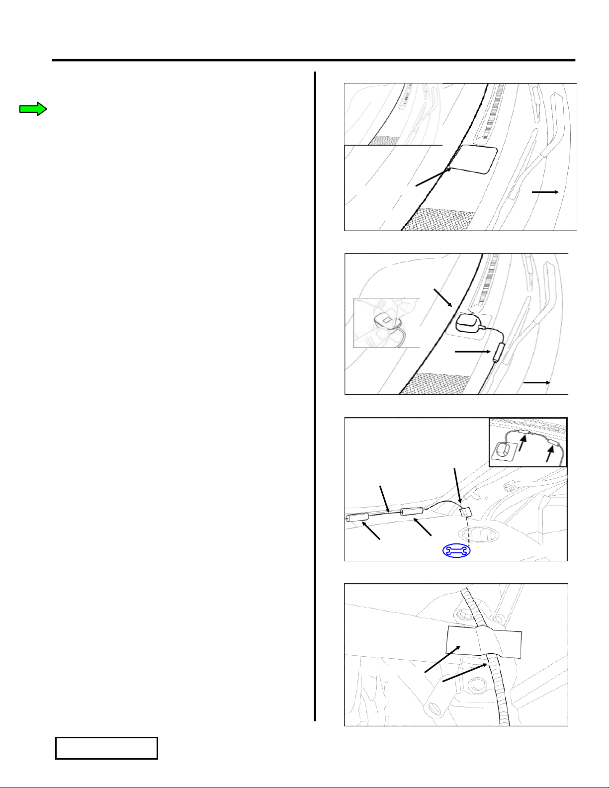
i. Verify that a satellite channel is received,
or a "NO SIGNAL" message appears on
the display.
NOTE: If "ANTENNA" appears (flashing) on
the display - then one or both of the antenna
cables are disconnected from the satellite tuner.
NOTE: If the head unit will not tune or go into
satellite mode - then the tuner cable is
disconnected from the satellite tuner.
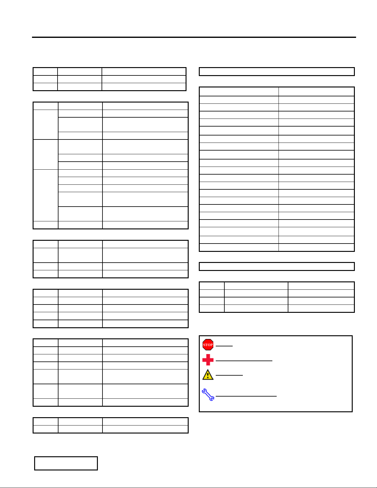
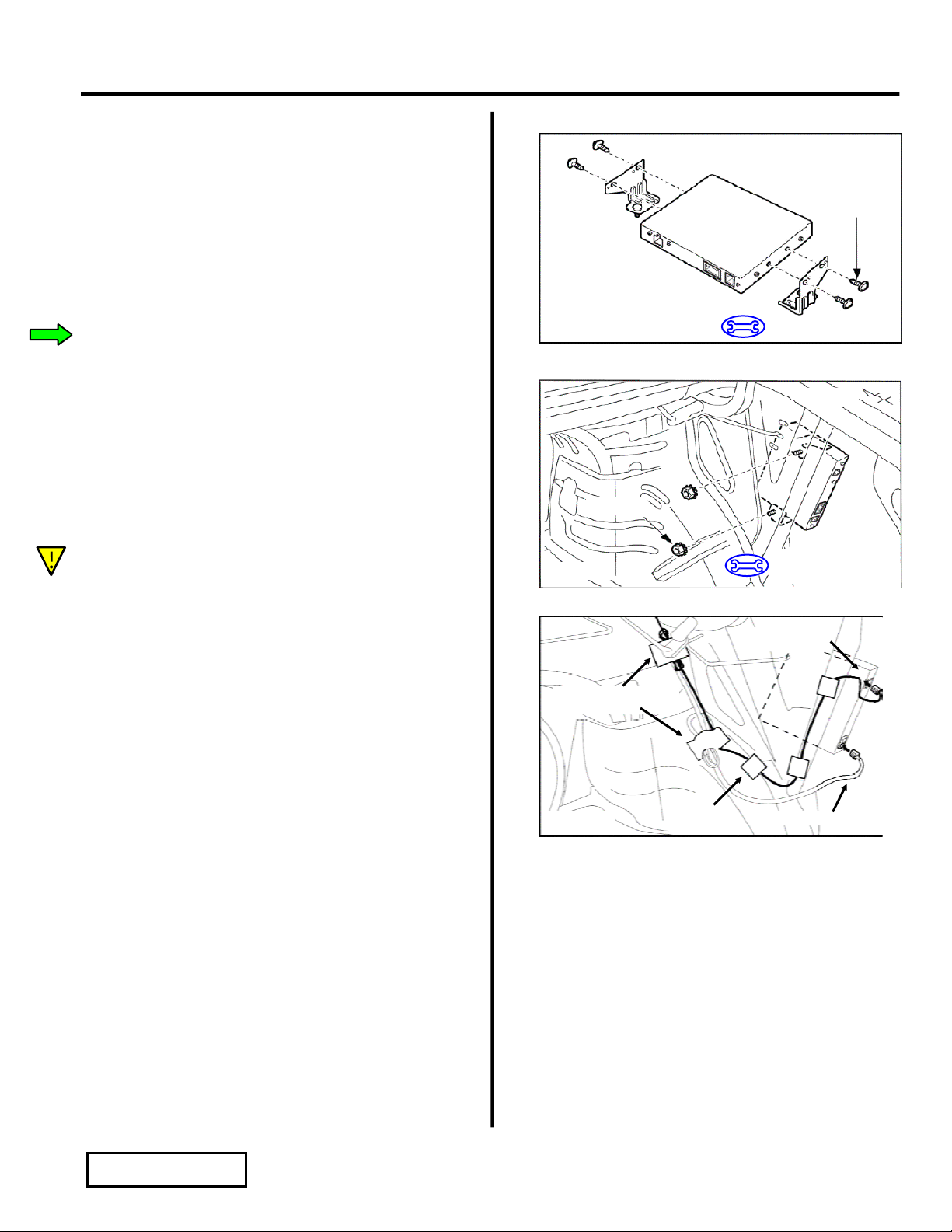
5. Disconnect battery negative cable.
G. Complete the Reassembly of Vehicle.
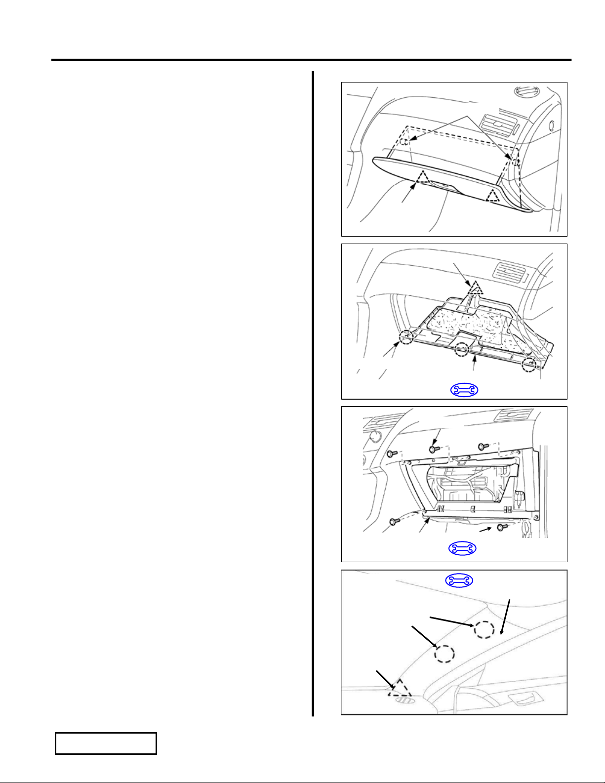
1. Reinstall the A pillar trim on the passenger
side.
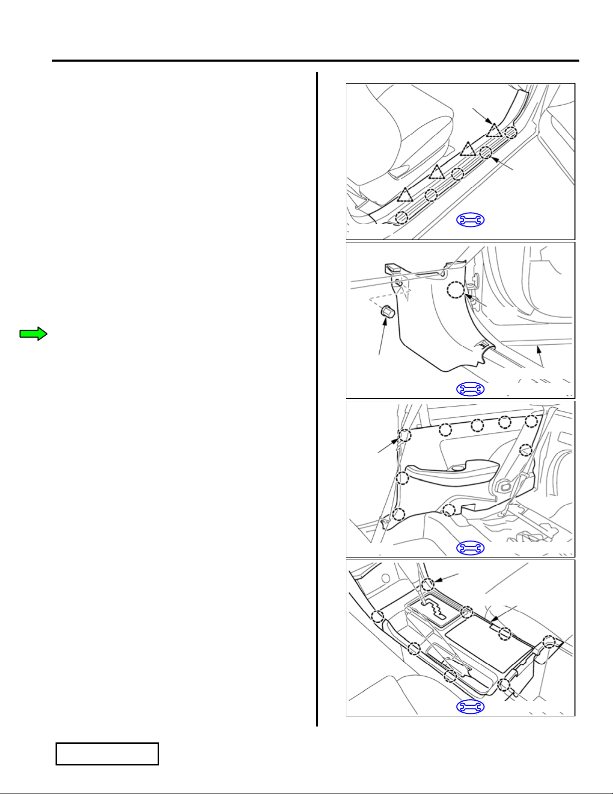
2. Reinstall the glove compartment door.
3. Reinstall the instrument cluster lower finish
panel.
4. Reinstall the instrument cluster upper finish
panel.
5. Reinstall the front console box.
6. Reinstall the upper console panel.
7. Reinstall the shift knob.
8. Reinstall the passenger side quarter trim panel.
9. Reinstall the passenger side cowl cover.
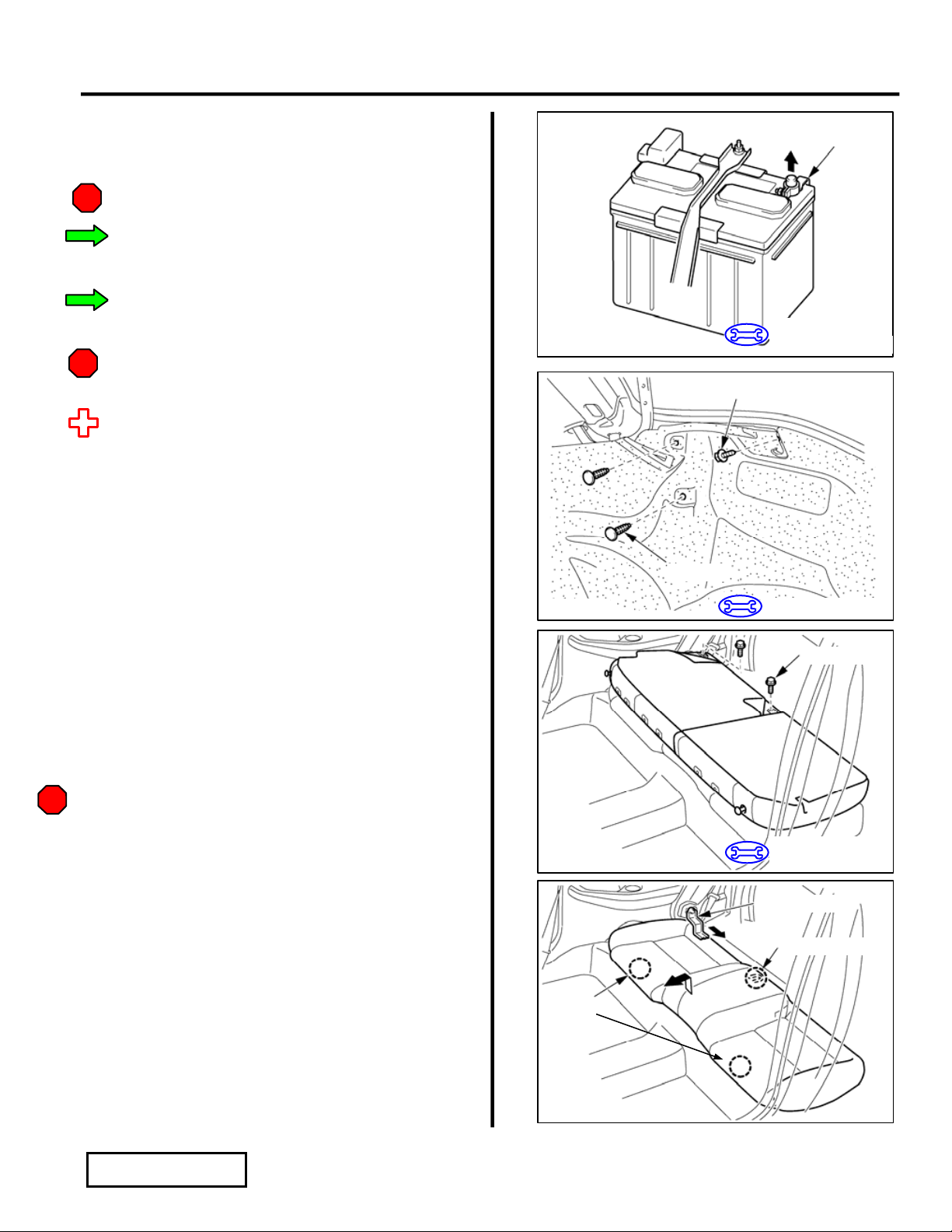
10. Reinstall the passenger side door scuff plate.
11. Re-assemble the rear seat.
i. Install the rear seat cushion, taking care
that the retaining hooks are securely
engaged.
ii. Bolt and attach the right rear seatback.
iii. Tighten outer bolt to 18 N-m (13 lbf-ft).
iv. Tighten inner bolt to 13 N-m (10 lbf-ft).
v. Fold up the seatback, and then fold down
the cover over the bolts.

TOYOTA SOLARA 2006 - XM SATELLITE RADIO TUNER
Section II – Installation Procedure
Issue Page 11 of 12 pages DIO
Issue: B 02/13/06
12. Re install the trim cover in the luggage
compartment.
13. Verify the panels fit together properly with no
uneven gaps between them.
H. Reconnect Battery Cable.
1. Reconnect the vehicle’s negative battery
cable. (Figure G1)
i. Position the negative terminal at original
factory position.
ii. Tighten the nut to 4.1 N-m (36 lbf-in).
iii. Do not touch the positive terminal with
any tool when replacing the cable.
2. Clean up and remove any trash.
3. Place the xM brochure in the glove box.
Figure H1
Socket (10 mm)
Torque Wrench
Negative
Battery
Cable

TOYOTA SOLARA 2006 - XM SATELLITE RADIO TUNER
Section III – Functional Verifications
Check: Look For:
Issue Page 12 of 12 pages DIO
Issue: B 02/13/06
Accessory Function Checks
Verify the proper operation of the satellite
radio tuner. Refer to the receiver assembly
and radio owner’s manuals.
Verify the proper operation of the receiver
assembly and radio. Refer to the receiver
assembly and radio owner’s manuals.
Vehicle Function Checks
Verify the proper operation of the hazard
switch.
Verify the rear passenger seat back is in the
upright position and the latch secured.
Verify the proper operation of the air
conditioning system.
Verify the proper operation of the multi-
information displays. (Clock, Temp., and
MPG meter)
Verify the proper operation of the L&R seat
heater switch.
Verify the proper operation of the 12V
outlet switch.
Table of contents