FUEL TANK INSTALLATION
The fuel tank must be purchased separately and installed by a qualified fuel supply technician.
NOTE: Fuel tank installation must comply with National Fire Protection Association Code NFPA 31 or local-
ly applicable codes. Check with local building officials.
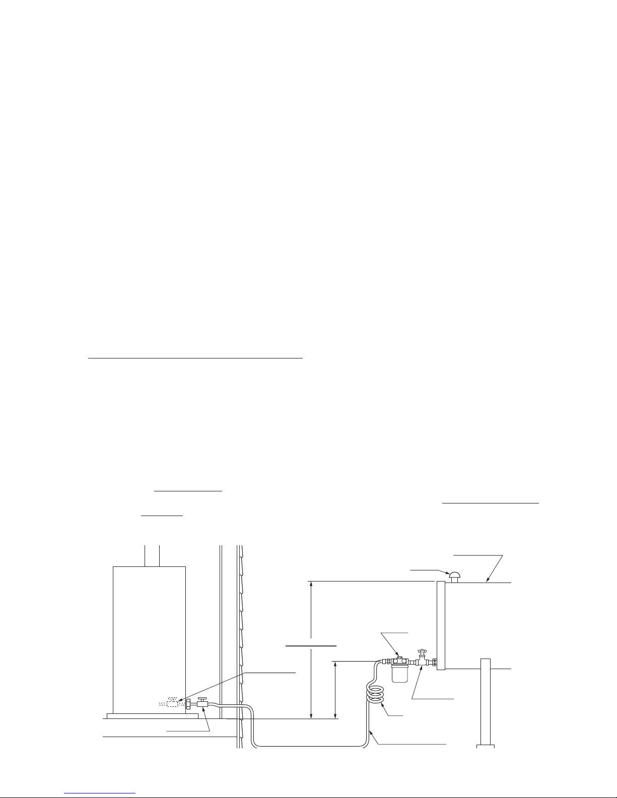
The following instructions should be followed for installation of a large capacity, gravity-fed fuel tank.
¡Installation height of tank's fuel outlet should be at least 16 in. above floor surface upon which the water
heater rests.
¡To avoid excess fuel pressure to water heater, the top of fuel tank should be no more than 8-1/2 ft. above
the bottom of the unit.
¡The inlet fuel pressure must not exceed 2.5 PSI. If the inlet pressure exceeds 2.5 PSI, a pressure reducer
(Part #10005099) must be used.
¡Fuel tank should be located at least 6 ft. away from all heat sources.
¡3/8" OD copper tubing should be used for the fuel line.
¡To prevent air locks in the fuel line, the fuel line should be smooth with no inverted U-shaped line or
sharp bends.
¡Install a UL listed fuel filter at the fuel tank outlet. Shut-off valves should also be installed on the fuel line
and connected to the tank as shown below. Unit should have a separate fuel line from fuel tank.
NOTE: An additional shut-off valve installed next to the exterior wall will minimize the amount of fuel to be
drained should the water heater need to be disconnected. If the valve is inside the building, a
fusible link type (Part #10005597) is recommended.
1. All external tank must be vented.
2. Install a UL listed fuel filter at the fuel tank outlet.
Specifications required of this fuel filter are as follows:
Type of Fuel: ASTM D3699 1-K kerosene, ASTM D396 Low Sulfre No. 1 or No. 2 Fuel Oil, or ASTM D975
Ultra Low Sulfur Diesel (ULSD)
Rated Filtering Capacity: 2 GPH (Minimum)
3. The fuel supply tank must be positioned as to allow gravity feed to the unit and high enough to reduce
trapped air in the fuel line. Please refer to Section “D”, page 8 in the Operation and Maintenance
Instructions for the procedure to remove trapped air. (✽)
NOTE: If the maximum height is exceeded, a fuel pressure limiting valve is required. Part No.
10005099 has 3/8 in. (N.P.T.) inlet and outlet female openings to accept the fuel line fittings.
NOTE: Fusible Link Valve (#10005597)
¡It is most important that the valve, depending on its use, be fully opened or fully closed.
¡The top nut on the valve (below the turn handle) is sealed and should never be tightened or
removed.
¡When installing fuel lines to the valve, be sure to check for fuel leakage.
¡A LEAKING VALVE SHOULD ALWAYS BE REPLACED.
5
Fusible link valve
Shut-off valve
8-1/2 ft. maximum
Tank vent
Outdoor fuel tank
Fuel filter
Shut-off valve
Loop
3/8in. OD copper tubing
(✽)
OM-180(in/E) 11.5.24 1:16 PM ページ 5
REMOVING AIR TRAP
When operating for the first time or when refueling an empty tank, air may be trapped in the fuel line, mak-
ing ignition difficult. In this situation, after removing the trapped air thoroughly from the fuel filter at the fuel
tank outlet, follow the procedures below:
1.
Press "POWER SWITCH" to "OFF" position. Disconnect the power supply cord.
2. Place a small container under the fuel strainer located inside the water
heater.
3. Loosen the screw on top of the strainer. Immediately wipe off any spilled
fuel.
4. Remove the trapped air thoroughly. Failure to remove all the air will cause a
noisy fuel pump, improper ignition and flame failure.
5. Tighten the screw after removing trapped air.
6. Plug into the receptacle. Press "POWER SWITCH" to "ON" position.
NOTE: In the event of an ignition failure, press "POWER SWITCH" to "OFF" position and after 10
seconds press "POWER SWITCH" to "ON" position once again.
TEMPERATURE AND PRESSURE RELIEF VALVE INSTALLATION
At the time of installation, a temperature and pressure relief valve complying with the standard for Relief
valve for Hot Water Supply System, ANSI, shall be installed in the threaded fitting on the water heater. Local
codes should govern the installation of the relief devices.
Specifications required of this temperature and pressure relief valve are as follows:
Inlet (male): 3/4 in.
Temperature relief: 210°F
Pressure relief setting: 150PSI
Rated capacity: Min. 148,000 BTU/H
(a) No other valve should be placed between the relief valve and the water heater.
(b) Discharge from the relief device is routed to a suitable place for disposal when relief occurs.
(c) No reducing coupling or other restrictions should be installed in discharge line.
(d) Discharge line should be installed to allow complete drainage of the water heater.
Note: Manual operation of pressure relief valves should be done at least once a year.
6
OM-180(in/E) 11.5.24 1:16 PM ページ 6
OM-180-K.indd 6 12/07/13 14:55


 User manual")


 Troubleshooting guide")

 User manual")


 Troubleshooting guide")


 User manual")
 Troubleshooting guide")

 null")
 null")