TBB CS series User manual

CS Combi User Manual
TBBPowerCo.,Ltd 1/17
CSseries
InverterChargerCombination
USERMANUAL
Version2.0
Date:Oct2010

CS Combi User Manual
TBBPowerCo.,Ltd 2/17
A
Ab
bo
ou
ut
t
T
TB
BB
B
TBBPowerisadedicateddesignerandmanufacturerofsophisticatedandenvironmentally
ruggedpowerelectronicsequipment.
Weareofferingawiderangeofpowerconversionproductfromstandaloneinverter,N+1
redundantinverter,UPStobatterycharger,inverterchargercombinationandsolarcharge
controller.
Weensureconsistentproductqualitybysubjectingeveryproducttostrictlychoiceofsuperior
qualitycomponents,rigoroustestingandburn‐inthroughouttheproductionprocess.TBB
PoweriscertifiedbyTUVinaccordancewithISO9001andcanbeyourreliablepowersolution
provider.
D
Di
is
sc
cl
la
ai
im
me
er
r
Unlessspeciallyagreedinwriting,TBBPowerCo.,Ltd
¾Takenowarrantyastotheaccuracy,sufficiencyofsuitabilityofanytechnicalorother
informationprovidedinthismanualorotherdocumentation.
¾Assumesnoresponsibilityorliabilityforlossordamage,whetherdirect,indirect,
consequentialorincidental,whichmightariseoutoftheuseofsuchinformation
A
Ab
bo
ou
ut
t
t
th
hi
is
s
M
Ma
an
nu
ua
al
l
Thismanualdescribesourproductfeaturesandprovidesprocedureofinstallations.Thismanualis
foranyoneintendingtoinstallourequipment.
C
Co
on
nt
ta
ac
ct
t
I
In
nf
fo
or
rm
ma
at
ti
io
on
n
TBBPowerCo.,Ltd
Web:www.tbbpower.com
Tel:+86‐592‐5212299
Fax:+86‐592‐5796070
Email:service@tbbpower.com

CS Combi User Manual
TBBPowerCo.,Ltd 3/17
G
Ge
en
ne
er
ra
al
l
I
In
ns
st
tr
ru
uc
ct
ti
io
on
n
ThanksforchoosingourproductsandthismanualweresuitableforCSseriesinvertercharger
combination.
Thischaptercontainsimportantsafetyandoperationinstructions.ReadandkeepthisUser
Guidewellforlaterreference.
TheCSseriesCombiSneedstobeinstalledbyprofessionalsandpleasepayattentiontothe
followingpointspriortoinstallation:
1>Pleasechecktheinputvoltageorvoltageofbatteryissametothenominalinputvoltageof
thisinverter.
2>Pleaseconnectpositiveterminal“+”ofbatteryto“+”inputoftheinverter.
3>Pleaseconnectnegativeterminal“‐”ofbatteryto“‐”inputoftheinverter.
4>Pleaseusetheshortestcabletoconnectandensurethesecureconnection.
5>Whileconnecting,pleasesecuretheconnectionandavoidshortcutbetweenpositive
terminalandnegativeterminalofbattery,whichwillcausedamageofbattery.
6>Inverterwillhavehighvoltageinside.Onlyauthorizedelectriciancanopenthecase.
7>TheinverterWASNOTdesignedtouseinanyliferetainingequipment.

CS Combi User Manual
TBBPowerCo.,Ltd 4/17
1
1.
.
G
Ge
en
ne
er
ra
al
l
S
Sa
af
fe
et
ty
y
I
In
ns
st
tr
ru
uc
ct
ti
io
on
n
1
1.
.1
1
S
Sa
af
fe
et
ty
y
I
In
ns
st
tr
ru
uc
ct
ti
io
on
n
AsdangerousvoltagesandhightemperatureexistwithintheCOMBIS,onlyqualifiedand
authorizedmaintenancepersonnelarepermittedtoopenandrepairit.
ThismanualcontainsinformationconcerningtheinstallationandoperationoftheCombiS.All
relevantpartsofthemanualshouldbereadpriortocommencingtheinstallation.Pleasefollow
thelocalstipulationmeantime.
Anyoperationagainstsafetyrequirementoragainstdesign,manufacture,safetystandard,and
areoutofthemanufacturerwarranty.
1
1.
.2
2
G
Ge
en
ne
er
ra
al
l
P
Pr
re
ec
ca
au
ut
ti
io
on
n
1.2.1Donotexposetodust,rain,snoworliquidsofanytype,itisdesignedforindooruse.DO
NOTblockoffventilation,otherwisetheINVERTERwouldbeoverheating.
1.2.2Toavoidfireandelectricshock,makesureallcablesselectedwithrightgaugeandbeing
connectedwell.Smallerdiameterandbrokencablearenotallowedtouse.
1.2.3Pleasedonotputanyinflammablegoodsneartoinverter.
1
1.
.3
3
P
Pr
re
ec
ca
au
ut
ti
io
on
n
r
re
eg
ga
ar
rd
di
in
ng
g
b
ba
at
tt
te
er
ry
y
o
op
pe
er
ra
at
ti
io
on
n
1.3.1.Useplentyoffreshwatertocleanincasebatteryacidcontactsskin,clothing,oreyesand
consultwithdoctorassoonaspossible.
1.3.2.Thebatterymaygenerateflammablegasduringcharging.NEVERsmokeorallowa
sparkorflameinvicinityofabattery。
1.3.3.Donotputthemetaltoolonthebattery,sparkandshortcircuitmightleadtoexplosion.
1.3.4.REMOVEallpersonalmetalitemssuchasrings,bracelets,necklaces,andwatcheswhile
workingwithbatteries.Batteriescancauseshort‐circuitcurrenthighenoughtomake
metalmelt,andcouldcausesevereburns.

CS Combi User Manual
TBBPowerCo.,Ltd 5/17
2
2.
.0
0
I
In
nt
tr
ro
od
du
uc
ct
ti
io
on
n
a
an
nd
d
S
Sp
pe
ec
ci
if
fi
ic
ca
at
ti
io
on
n
2
2.
.1
1
I
In
nv
ve
er
rt
te
er
r
C
Ch
ha
ar
rg
ge
er
r
C
Co
om
mb
bi
in
na
at
ti
io
on
n
I
In
nt
tr
ro
od
du
uc
ct
ti
io
on
n
CombiSisaninverter/chargerscombinationprovidingtruesine‐waveinverter,threestage
batterychargingandahighspeedACtransferswitchaswell.Itissuitableforthemost
demandingmobileandoffgridapplication.
+
++
+
P
Pu
ur
re
e
S
Si
in
ne
e
W
Wa
av
ve
e
o
ou
ut
tp
pu
ut
t
CombiSproducesvirtuallydistortionfreesine‐waveACpowerforhouseholdapplianceand
sensitiveelectronicswithoutworry,suchasTV,stereo,laptop.
+
++
+
S
So
op
ph
hi
is
st
ti
ic
ca
at
te
ed
d
B
Ba
at
tt
te
er
ry
y
C
Ch
ha
ar
rg
ge
er
r
zPowerfactorcorrectedbatterycharginggetsthemostoutofyourshorecord.
zThreestagechargingalgorithmguaranteeyourbatterygettingthequickandright
maintenance.
zMeantime,itoffervariouschargingalgorithmformultiplebatterychemicalsincluding
AGM,GEL,MaintenanceFree…
zTemperaturecompensationforbettercharging(newmodel,comingfromMar2011).
+
++
+
U
Un
ni
in
nt
te
er
rr
ru
up
pt
te
ed
d
A
AC
C
P
Po
ow
we
er
r
Inevenofagridfailure,theoutputwillswitchtoinverterautomaticallyandtakeoverthe
powersupplytotheload.Thetransfertimeisultrafast(ab.10ms)thattheITloadwillnotbe
interrupted.
+
++
+
O
Ou
ut
ts
st
ta
an
nd
di
in
ng
g
o
ov
ve
er
rl
lo
oa
ad
d
c
ca
ap
pa
ab
bi
il
li
it
ty
y
CombiSprovidedwithoutstandingoverloadcapabilityintogetherwithsuperfastprotection
makeitsuitableforallkindsofload,especiallyforheavyloadlikeair‐con,fridge,powertools
etc.
+
++
+
R
Re
em
mo
ot
te
e
c
co
on
nt
tr
ro
ol
l
a
an
nd
d
c
co
om
mm
mu
un
ni
ic
ca
at
ti
io
on
n
WeofferremotecontrollerandRS485communicationportmakeitconvenienttouseandapply
toanysystem.
+
++
+
R
Ro
ob
bu
us
st
t
C
Co
on
ns
st
tr
ru
uc
ct
ti
io
on
n
Therobustaluminumconstruction(forstructureAandBonly),featuringlightweightand
corrosionresistant

CS Combi User Manual
TBBPowerCo.,Ltd 6/17
2
2.
.2
2
S
Sp
pe
ec
ci
if
fi
ic
ca
at
ti
io
on
n
Electrical
DC Input AC Output
Norminal Voltage 12VDC / 24VDC / 48VDC 12VDC: 600W-3000W
Min start voltage 10.4V / 20.8V / 41.6V 24VDC: 600W-5000W
Low voltage protection 10.5V / 21V / 42V Output power 48VDC: 600W-6000W
Low voltage disconnect 10.2V / 20.4V / 40.8 Wave form Pure sine wave
Power factor 0.9-1.0
AC Input Norminal output 110/230VAC
Nominal Input AC
voltage 230VAC Voltage variation Max ± 2%
Low voltage disconnect 184VAC ± 4% Output frequency 50/60Hz
Minimum engage 194V ±4% <3% liner load
High vol. disconnect 270V ±4% THD <5% non-liner load
High voltage reengage 260V ±4% Crest factor 3:1
Nominal input fre. 50Hz/60Hz - auto detec Efficiency 88%
Low frequency trip 47Hz/57Hz Overload 120% 15mins
High frequency trip 55Hz/65Hz 150% 1min
Short circuit protection Circuit breaker 40W - normal mode
Overload protection Circuit breaker Status Power
Consumption <25W - power save
mode
Dynamic response
time < 20ms
Safety & Enviroment DC Output
Operating Temp. -25C - 50C full load Input range 196V-245VAC
Storage Temp. -40C - 85C full load Battery types multi to be selectable
Isolation AC - DC : 2000Vrms Nominal output 12VDC/24VDC/48VDC
DC – ground : 2000Vrms Output current refer to separate list
AC - ground : 2000Vrms De-sulphation 15.5V / 31V / 62V
Standard
Safety EN60950-1
Emmission EN55022
Immunity EN55022

CS Combi User Manual
TBBPowerCo.,Ltd 7/17
Model CS0625L CS1035L CS1545L CS2065L CS3075L
Nomi. DC input voltage 12V
continuous power (W) 600 1000 1500 2000 3000
Nominal output voltage 12V
Output current (A) 25 35 45 65 75
De-sulphation 15.5V for 4hrs
Size 420x180x135 460x180x180 640x180x180
Weight (kgs) 9.5 14 16 18.5 28
Model CS0615M CS1020M CS1530M CS2035M CS3045M CS4065M CS5070M
Nomi. DC input voltage 24V
continuous power (W) 600 1000 1500 2000 3000 4000 5000
Nominal output voltage 24V
Output current (A) 15 20 30 35 45 65 70
De-sulphation 31V for hours
Size 420x180x135 460x180x180 640x180x180
Weight (kgs) 9.5 14 16 18.5 22.5 34.5 38
Model CS2020S CS3030S CS4035S CS5040S CS6050S
Nomi. DC input voltage 48V
continuous power (W) 2000 3000 4000 5000 6000
Nominal output voltage 48V
Output current (A) 20 30 35 40 50
De-sulphation 62V for 4hrs
Size 460x180x180 640x180x180
Weight (kgs) 18.5 22.5 34.5 38 42

CS Combi User Manual
TBBPowerCo.,Ltd 8/17
2
2.
.3
3
M
Mo
od
de
el
l
d
de
ef
fi
in
ni
it
ti
io
on
n
fieldfigureexplanation
CSseriesname
6600W
101000W
151500W
202000W
303000W
404000W
505000W
X
60
Inverteroutputpower:10=1000W
6000W
2525A
3535A
4545A
6565A
Y
75
Chargercapacity
75A
L12VDC
M24VDC
Z
S
BatterybankVoltage
48VDC
Example:
CS1500M:PureSineWaveInverter24V1500W
CS3000L:PureSineWaveInverter12V3000W
CS1545L:InverterChargerCombination12V1500W45A

CS Combi User Manual
TBBPowerCo.,Ltd 9/17
3
3.
.0
0
S
St
tr
ru
uc
ct
tu
ur
re
e
a
an
nd
d
D
Di
is
sp
pl
la
ay
y
3
3.
.1
1
S
St
tr
ru
uc
ct
tu
ur
re
e
ThereisthreesizeavailableinCSseries,pleaserefertospecificationforeachmodel
Size (LxWxH)
Structure A 420x180x135
Strucuure B 460x180x180
Structure C 640x180x180

CS Combi User Manual
TBBPowerCo.,Ltd 10/17
3
3.
.2
2
D
Di
is
sp
pl
la
ay
y
3
3.
.2
2.
.1
1
T
To
op
p
p
pa
an
ne
el
l
d
di
is
sp
pl
la
ay
y
3
3.
.2
2.
.2
2
F
Fr
ro
on
nt
t
p
pa
an
ne
el
l
d
di
is
sp
pl
la
ay
y
ThreeLEDindicatingworkingmodeandfault.
3
3.
.2
2.
.3
3
R
Re
em
mo
ot
te
e
C
Co
on
nt
tr
ro
ol
ll
le
e
CSinverterchargercombination
3
3.
.3
3.
.1
1
F
Fr
ro
on
nt
t
P
Pa
an
ne
el
l

CS Combi User Manual
TBBPowerCo.,Ltd 11/17
A DC cable through hole
B Main switch
C LED
D Gland for remote control cable
E Gland for AC input
F Gland for AC output
G DC cable through hole
3
3.
.3
3.
.2
2
C
Ce
en
nt
tr
ra
al
l
P
Pa
an
ne
el
l
Loosescrewandremovethetoppanelyouwillseethecentralpanelwhereallconnection
blocklocated.
A Cable to front panel switch
B Remote Control connecter
C Battery Switch
D AC Input
E AC output
F Inverter output over current protection
G DC +
H DC -
I Charger input overcurrent protection

CS Combi User Manual
TBBPowerCo.,Ltd 12/17
4
4.
.0
0
I
In
ns
st
ta
al
ll
la
at
ti
io
on
n
4
4.
.1
1
M
Ma
at
te
er
ri
ia
al
l
l
li
is
st
t
Theunitispackedwithfollowingmaterials:
¾equipment
¾Pleaseconfirmtheseriesnumberoninverterissametothatonoutercarton.
¾CableandCableTerminal
¾M6screw,Fuses,breakersetc.
¾Tools
4
4.
.2
2
L
Lo
oc
ca
at
ti
io
on
n
PleaseinstalltheequipmentinalocationofDry,Clean,Coolwithgoodventilation.
¾Workingtemperature:0‐40℃
¾Storagetemperature:‐40‐70℃
¾RelativeHumidity:0%‐95%,non‐condensing
¾Cooling:forcedair
¾Vertical angle:No vibration and hanging angle less than 5 degree
4
4.
.3
3
W
Wi
ir
ri
in
ng
g
Pleasefindthefollowingminimumwiresize
AC wiring DC wiringSystem
capacity 110VAC 220VAC 48VDC 24DC 12VDC
600W 2mm²2mm²4mm²6mm²12mm²
1KW 4mm²2mm²6mm²12mm²20mm²
1.5KW 4mm² 2mm²8mm² 16mm²
32mm²
2KW 6mm² 2.5mm² 12mm² 25mm² 40mm²
3KW 8mm² 4mm² 16mm² 35mm² \
4KW 10mm² 5mm² 21mm² 42mm² \
5KW 12mm² 6mm² 26mm² 52mm² \
6KW 14mm² 7mm² 32mm² \ \

CS Combi User Manual
TBBPowerCo.,Ltd 13/17
4
4.
.4
4
G
Ge
en
ne
er
ra
al
l
a
ad
dv
vi
ic
ce
e
¾EnsurethattheinverterhasthecorrectDCvoltagewithyourexistingbatterysystem
¾InstalltheCSasclosetothebatteriesaspossiblereducingthevoltagedroponcableforthe
betterperformanceoftheequipment
DonotconnecttheoutputofthisequipmenttoyourACsystematthesametimeas
anyotherA/Csourcesuchasthe230Vexternalmainsoragenerator.
¾WerecommendconnectingaDCfusebetweenbatteryandCS.Thefusewillofferprotection
tothesystemincaseoffailure.
¾OntheACoutputside,werecommendconnectingtheoutputfromtheinvertertoasuitable
ResidualCurrentCircuitBreakerandCircuitBreaker.
¾OntheACinputside,thefusewasdeterminedbythepoweryouused.Maxpowerofthisseries
is30A.
4
4.
.5
5
I
In
ns
st
ta
al
ll
la
at
ti
io
on
n
Fortheuseroperationsafety,cutoffthepowerbeforeinstallation
4
4.
.5
5.
.1
1
P
Pl
la
ac
ce
e
t
th
he
e
u
un
ni
it
t
UseM6tofixtheunitsecurelyonthesurface
4
4.
.5
5.
.2
2
C
Co
on
nn
ne
ec
ct
ti
in
ng
g
t
th
he
e
c
ca
ab
bl
le
e
¾Loosethescrewandremovethetoppanel
¾(ifnecessary)ThereiscableconnectingtheLED/switchoffrontpaneltoequipment,please
plugouttheconnectoratfrontpanel.Then,loosethescrewandremovethefrontpanel
CS Combi User Manual
TBBPowerCo.,Ltd 14/17
¾PullthroughtheDCcablethroughthehole,clampthecableterminaloncable.
¾ConnectDCinputcable:choosetherightcablesizeandfollowpolarityguidemarkedonthe
panel.SecurethebatterycableonDCterminal.
¾PullthroughtheACinputcablethroughGlandandconnectitonACinputblock
¾PullthroughtheACoutputcablethroughGlandandconnectitonAConputblock
¾Ifnecessary,pullthroughtheremotecontrollercablethroughGlandandconnectiton
communicationport.
¾Installthefrontpanel,connectthefrontpaneldisplaycable.tighteningofallGland
¾Installedthetoppanel
PleasedoublechecktheACinputandACoutputwasrightafterconnection.
Wrongconnectionwillcausepermanentdamageofequipmentanditisoutof
warranty.
4
4.
.5
5.
.3
3
I
In
ns
st
ta
al
ll
l
t
th
he
e
r
re
em
mo
ot
te
e
c
co
on
nt
tr
ro
ol
ll
le
er
r
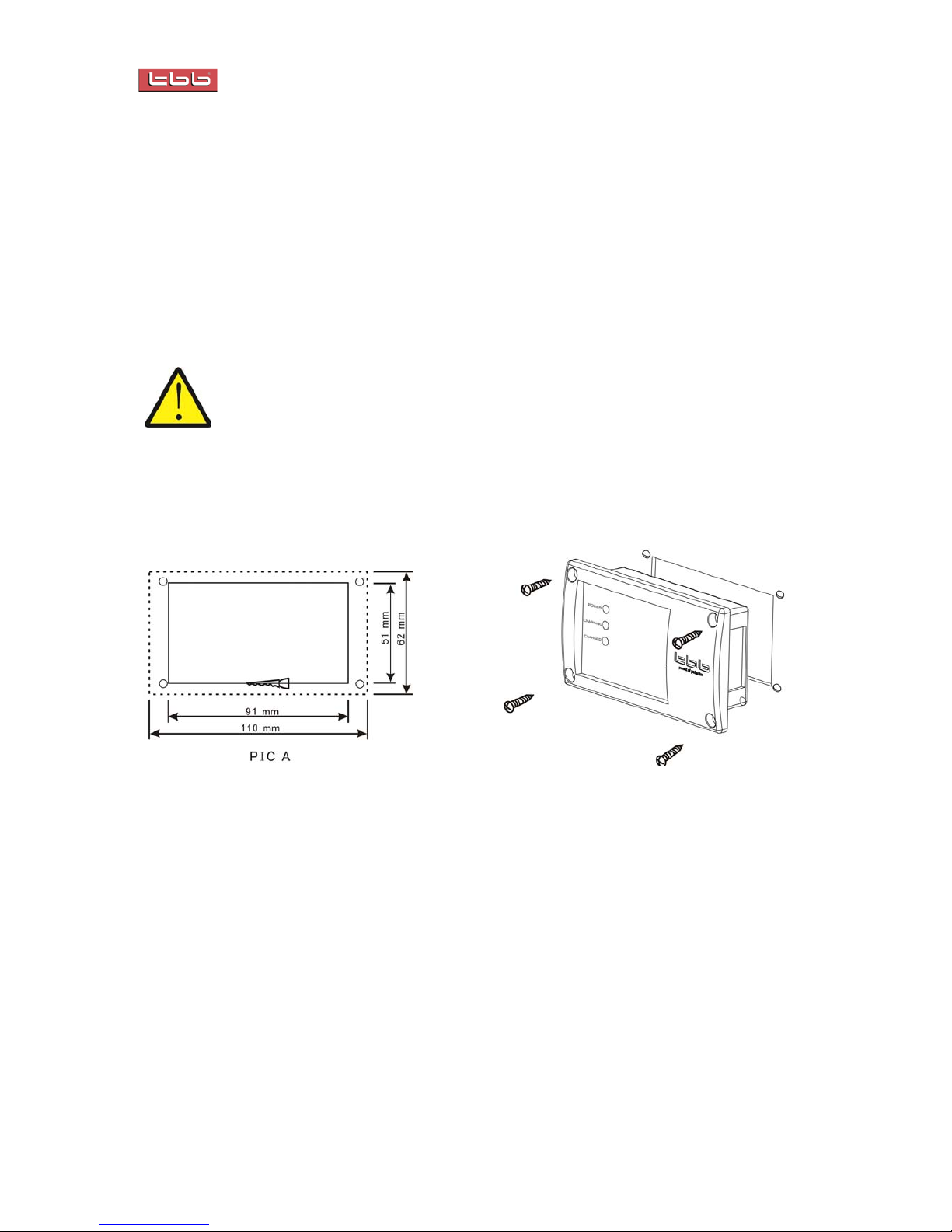
Pleasecuttheholeaccordingtofollowingsizeandscrewtheremotecontrollersecurelythroughfour
screwatcorners.

CS Combi User Manual
TBBPowerCo.,Ltd 15/17
5
5.
.0
0
O
Op
pe
er
ra
at
ti
io
on
n
5
5.
.1
1
S
Se
et
tt
ti
in
ng
g
B
Ba
at
tt
te
er
ry
y
t
ty
yp
pe
e
s
se
et
tt
ti
in
ng
g:Pleaseselectthebatterytypeattheclockdiagram,orchoosethetype
followthebatterymanufacturerrecommendation.Followingpleasefindthelistofavailable
batterytype
SwitchsettingBatterytypeAbsorption Float
0NOUSE
1GEL11413.7
2AGM114.113.4
3AGM214.613.7
4Sealedleadacid14.413.6
5GEL214.413.8
6Openleadacid14.813.3
7Calcuim15.113.6
8Desulphation15.5Vwithmax4hrstimer
9NOUSE
Pleasereferto5.5fordetailsofde‐sulphationcharging.
5
5.
.2
2
D
Do
ou
ub
bl
le
e
C
Ch
he
ec
ck
ki
in
ng
g
¾ChecktheDCinputvoltageofthisinverterissametoyourbatterynominalvoltage.NEVER
trytoconnectdifferentDCinputtoinv
¾InspecttherightpolarityofDCinput,otherwiseunitcannotpowerON.
¾InspectACinputandACoutputiscorrect,makesureunitisnoshortcut
5
5.
.3
3
S
Sw
wi
it
tc
ch
h
o
on
n
t
th
he
e
i
in
nv
ve
er
rt
te
er
r
¾LeaveACinputswitchoff,switchingontheunit,theledswillcyclethroughanalysisthenthere
shouldbeACavailableatinverteroutput.
¾ThenswitchontheACinput,thecombiSshouldgoonbypassmodefeedingthepowerintoload
andmeantimebatterychargerwillstartwork.
5
5.
.4
4
P
Po
ow
we
er
r
S
Sa
av
vi
in
ng
g
m
mo
od
de
e
¾Incasethereisnoload,youcouldchoosetheequipmententeringintopowersavingmode
throughpresstheswitcheitheronmainpanelorremotecontroller.Afterenteringinto
powersavingmode,theequipmentstatuspowerconsumptionwillbedramaticallyreduced.

CS Combi User Manual
TBBPowerCo.,Ltd 16/17
5
5.
.5
5
P
Pe
er
rf
fo
or
rm
mi
in
ng
g
D
De
es
su
ul
lp
ph
ha
at
ti
io
on
n
C
Ch
ha
ar
rg
gi
in
ng
g
Itisstronglyrecommendedtoreadthissectioncarefullybeforeyousetthe
de‐sulphationchargingandDONOTleavebatteryunattendedwhileperforming
de‐sulphation.
About Desulphation
Frequency:Maximumonceamonth,youmaywishtoequalizeyourfloodedbatteriesbyusing
thebatterychargerequalizationmode.
Important:Equalizationcandamageyourbatteriesifitisnotperformedproperly.Never
equalizeabatterymorethantwiceamonth.Alwayscheckbatteryfluidbeforeand
afterequalization.Fillbatteriesonlywithdistilledwater.
AlwayschecktheequalizationswitchissetbacktoOFFaftereachtime’s
equalization.
Batterymanufactures’recommendationsonequalizationvary.Alwaysfollowthe
batterymanufacturer’sinstructionssobatteriesareproperlyequalized.Asaguide,a
heavilyusedbatterymayrequireequalizationonceamonthwhileabatteryinlight
dutyservice,onlyneedsequalizingonceevery2to4months.
BatterytypeOnlyperformequalizationtofloodedlead‐acidbatteries.DonotequalizeGel,AGM
batteries.
Performing an Equalization
Duringequalization,thebatterygeneratespotentiallyflammablegases.Followallthe
batterysafetyprecautionslistedinthisguide.Ventilatetheareaaroundthebattery
thoroughlyandensurethattherearenosourcesofflameorsparksinthevicinity
Whenbatterytemperaturereachabove50C,pleasestopcharging.

CS Combi User Manual
TBBPowerCo.,Ltd 17/17
Turnoffordisconnectallloadsonthebatteryduringequalization.Thevoltageappliedtothebattery
duringequalizationmaybeabovethesafelevelsforsomeloads.Besuretocheckbatteryelectrolyte
beforeandafterequalization.Fillonlywithdistilledwater.
Pleasemonitorthevoltagewhileperformingthede‐sulphationcharging,
¾Whenyouswitchonthischarging,youwillseethevoltageincreasetofull(15.5Vfor12Vbattery,
31Vfor24Vbattery)
¾Aftersometime(thereisatimerinside),thevoltagewilldropto11V/22V,whichindicatethis
chargingfinished.
¾Youcanswitchoffthecombi,changethesettingbacktonormal
¾SwitchontheCSagainfornormaloperation.
6
6.
.0
0
T
Tr
ro
ou
ub
bl
le
e
S
Sh
ho
oo
ot
ti
in
ng
g
LED on front panel
Status Description Charger Inverter Charging Charged Over
load
Over
temp
Fault
Constant current charge ON ON
Constant voltage charge ON flash
Charger
Float ON ON
Inverter Inverter ON ON
Battery low voltage ON ON
Battery high volt ON ON
Over load ON ON ON
Over temp (inverter mode) ON ON ON
Over temp (charger mode) ON ON ON
Fault
Over charge ON ON ON
This manual suits for next models
17
Table of contents
Other TBB Inverter manuals


