TPS 901-PH User manual

Congratulations !
You have purchased the latest in benchtop pH-mV-Temperature instrumentation.
We trust that your new 901-PH will give you many years of reliable service.
The 901-PH is a breeze to operate. This manual has been designed to help you
get started, and also contains some handy application tips. If at any stage you
require assistance, please contact either your local TPS representative or the TPS
factory in Brisbane.
The manual is divided into the following sections:
1. Table of Contents
Each major section of the handbook is clearly listed. Sub-sections have also
been included to enable you to find the information you need at a glance.
2. Introduction
The introduction has a diagram and explanation of the display and controls of
the 901-PH. It also contains a full listing of all of the items that you should
have received with your 901-PH. Please take the time to read this section, as
it explains some of items that are mentioned in subsequent sections.
3. Main Section
The main section of the handbook provides complete details of the 901-PH,
including operating modes, calibration, troubleshooting, specifications, and
warranty terms.
4. Appendices
Appendices containing background information and application notes are
provided at the back of this manual.
TPS Pty Ltd
4 Jamberoo Street
Springwood, Brisbane,
Australia, 4127
Phone :(07) 32 900 400
International :61 7 32 900 400
Fax :(07) 3808 4871
International :61 7 3808 4871
Email :[email protected]
Web Site :www.tpssite.com.au
Model 901-PH
pH-mV-Temp.
Meter
Handbook Version : 5
Date : 30-Aug-99
Author : MS

Page 1
Contents
1. Introduction..............................................................................................2
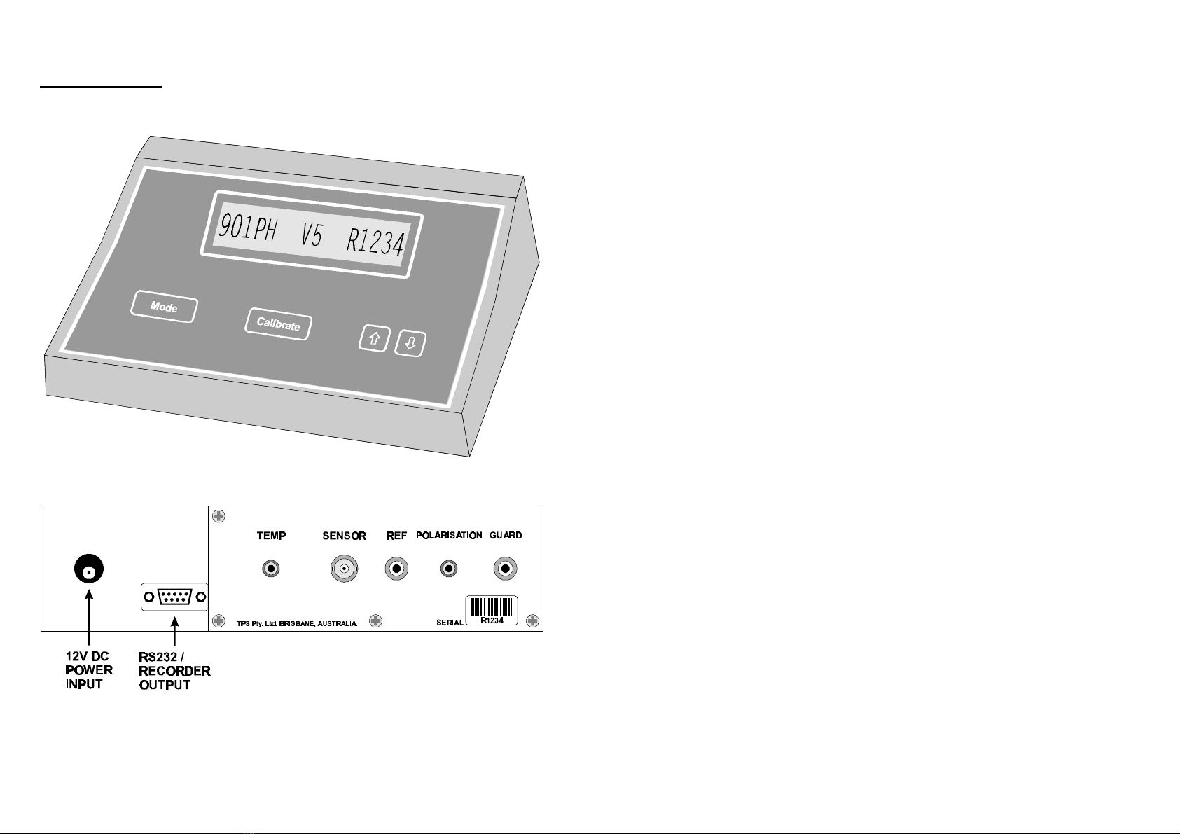
1.1 901-PH Display and Controls............................................................................2
1.2 901-PH Rear Panel Connectors..........................................................................2
1.3 901-PH Front Panel...........................................................................................3
1.4 Unpacking Information .....................................................................................4
1.5 Specifications....................................................................................................5
2. Operating Modes......................................................................................6
3. pH Calibration ..........................................................................................7
3.1 Calibration Procedure........................................................................................7
3.2 Calibration Notes ..............................................................................................8
3.3 Calibration Messages ........................................................................................9
4. mV Calibration........................................................................................ 10
5. Temperature Calibration........................................................................ 10
5.1 Calibration Procedure......................................................................................10
5.2 Calibration Notes ............................................................................................11
5.3 Calibration Messages ......................................................................................11
5.4 Manual Temperature Setting ...........................................................................12
6. RS232 Port.............................................................................................. 13
6.1 Setting the Baud Rate......................................................................................13
6.2 Sending Readings to the RS232 Port................................................................13
6.3 RS232 Configuration ......................................................................................14
6.4 Communication and Statistical Software..........................................................14
6.5 Commands......................................................................................................14
6.6 Data Format....................................................................................................15
7. Recorder Output Option ........................................................................ 16
7.1 RS232 / Recorder Output Socket Connections .................................................16
8. Selecting Buffers for Automatic Buffer Recognition............................ 17
9. Initialising the 901-PH............................................................................ 18
10. Troubleshooting..................................................................................... 19
10.1 General Error Messages ..............................................................................19
10.2 pH and mV Troubleshooting .......................................................................20
10.3 Temperature Troubleshooting......................................................................21
11. Appendices............................................................................................. 22
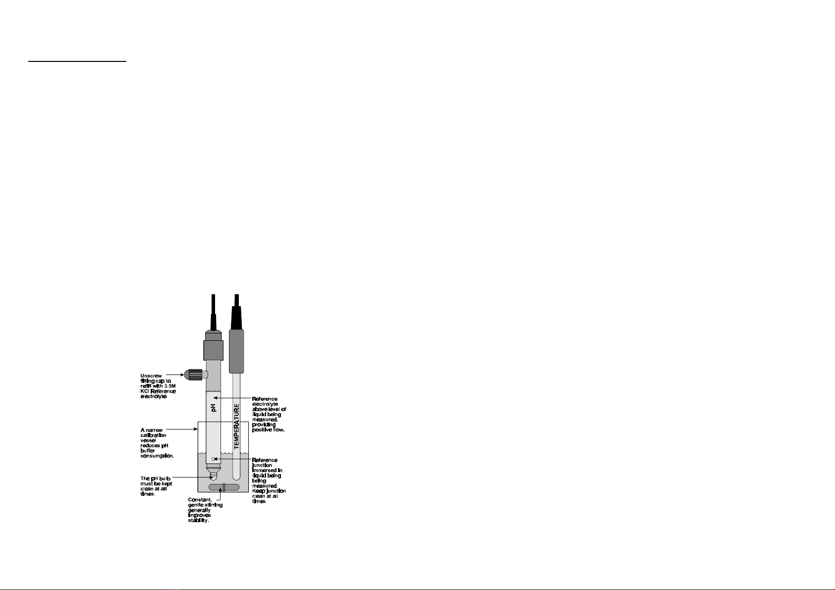
11.1 pH Sensor Fundamentals.............................................................................22
11.2 Polarisation Output Connector.....................................................................24
11.3 Guard Connector.........................................................................................25
11.4 Checking the reference junction of a pH sensor............................................25
11.5 Determining if an instrument or sensor is faulty...........................................26
12. Warranty ................................................................................................. 27

Page 2
1. Introduction
1.1 901-PH Display and Controls
1.2 901-PH Rear Panel Connectors

Page 3
1.3 901-PH Front Panel
Display
•16 character alphanumeric LCD with 14.5 mm characters.
•pH/mV and Temperature can be displayed simultaneously.
•User friendly text prompts and error messages.
•Serial number is displayed when the 901-PH is switched on.
Key
•Switches between pH, mV, Temperature and 2 optional RS232 modes. See
section 2.
Key
•Used to calibrate pH and Temperature. See sections 3and 5.
•Also used to select buffers for automatic buffer recognition. See section 8.
and Keys
•Used for temperature calibration. See section 5.
•Used for setting the manual temperature compensation value if the
temperature sensor is unplugged. See section 5.4.
•Press to recall asymmetry value from the last successful pH calibration.
•Press to recall slope value from the last successful pH calibration.
•Used to select baud rate when optional RS232 port is fitted. See section 6.1.
•Used to select output "send" rate when optional RS232 port is fitted. See
section 6.2

Page 4
1.4 Unpacking Information
Before using your new 901-PH, please check that the following accessories have
been included: Part No
1. 901-PH pH-mV-Temperature Instrument 121102
2. Combination pH Sensor 121207
3. Temperature/ATC Sensor 121245
4. pH6.88 Buffer, 200mL 121306
5. pH4.00 Buffer, 200mL 121381
6. AC/DC Power Adaptor 130044
7. 901-PH Handbook 130050
Options that may have been ordered with your 901-PH:
1. Solution Guard Rod 121360
2. Double Platinum Electrode for Karl Fischer 122207
Titrations
3. Flexible arm type sensor holder 130088
4. RS232 option (includes cable) 130029
5. RS232 Communication software for Windows 130086
6. Recorder output option (includes cable) 130028
7. Recorder PLUS RS232 option (includes cable) 130049

Page 5
1.5 Specifications
Ranges Resolution Accuracy
pH 0 to 14.00 pH 0.01 pH ±0.01 pH
mV 0 to ±600.0 mV
0 to ±1500 mV
(auto-ranging)
0.1 & 1 mV ±0.15 & ±1 mV
Temperature -10.0 to 120.0 OC0.1 OC±0.2 OC
Input Impedance :>3 x 10¹² Ω
Asymmetry Range :-1.00 to 1.00 pH
Slope Range :85.0 to 105.0%
Temperature Compensation :0 to 100.0 oC, automatic or manual
Recorder Output :pH :0 to 14.00 pH for 0 to 2000 mV
i.e. pH7.00 = 1000 mV
mV :-1500 to +1500 mV for 0 to 2000 mV
i.e. 0 mV = 1000 mV
Temp :-10.0 to 120.0 OC for 0 to 2000 mV
i.e. 0.0 OC = 152 mV
Output impedance approx 1000 Ohms.
Power :12V DC by AC/DC power adaptor.
Dimensions :270 x 210 x 75 mm
Mass :Instrument only:Approx 1.0 kg
Full Kit :Approx 2.5 kg
Environment Temperature :0 to 45 oC
Humidity :0 to 90 % R.H.

Page 6
2. Operating Modes
If the 901-PH IS NOT fitted with the RS232 option, press the key to roll
through the three operating modes as follows…
pH Mode 7.00pH 25.07.00pH 25.0oocc
↓↓
mV Mode 500.0mV 25.0500.0mV 25.0oocc
↓↓
Temperature Mode 25.025.0oocc
↓↓
Back to pH Mode
If the 901-PH IS fitted with the RS232 option, press the key to roll
through the five operating modes as follows…
pH Mode 7.00pH 25.07.00pH 25.0oocc
↓↓
mV Mode 500.0mV 25.0500.0mV 25.0oocc
↓↓
Temperature Mode 25.025.0oocc
↓↓
RS232 Send Rate Send RateSend Rate ↑↑ 00↓↓
↓↓
RS232 Baud Rate Baud RateBaud Rate ↑↑96009600↓↓
↓↓
Back to pH Mode

Page 7
3. pH Calibration
3.1 Calibration Procedure
1. Switch the 901-PH on and select pH mode (section 2).
2. Plug the pH sensor into the Sensor socket and the temperature sensor into
the Temp socket.
3. Ensure that temperature has already been calibrated or manually set (see
sections 5.1 and 5.4). NOTE: A " ∗∗ " in place of the decimal point in the
temperature readout indicates that temperature is not calibrated.
4. Ensure that the primary and secondary buffers to be used have been
correctly selected for automatic buffer recognition. See section 8.
5. Remove the wetting cap from the pH sensor.
6. Rinse the pH and Temperature sensors in distilled water and blot them dry.
7. Place both sensors into a small sample of primary buffer (pH6.88 or pH7.00)
so that the bulb and reference junction are both covered, as per the diagram
below.
DO NOT place the sensors directly into the buffer bottle.

Page 8
8. When the reading has stabilised, press the key to calibrate. If a 1
point calibration has been performed, a " ∗∗ " in place of the decimal point
will not be removed until a full 2 point calibration has been performed.
9. Rinse the pH and Temperature sensors in distilled water and blot them dry.
10. Place both sensors into a small sample of secondary buffer (pH4.00, pH9.23
or pH10.01) so that the bulb and reference junction are both covered, as per
the diagram in step 7 above.
DO NOT place the sensor directly into the buffer bottle.
NOTE: pH9.23 and pH10.01 buffers are highly unstable. Avoid using
these buffers if possible. Discard immediately after use.
When the reading has stabilised, press the key to calibrate.
The " ∗∗ " in the pH reading will now be replaced by a decimal point if
calibration was successful.
11. The 901-PH is now calibrated and is ready for use.
Discard the used samples of buffer.
3.2 Calibration Notes
1. A 1-point calibration should be performed at least weekly. In applications
where the sensor junction can become blocked (eg. wines, dairy products,
mining slurries etc) a 1-point calibration may have to be done daily.
2. A full 2-point calibration should be performed at least monthly. Of course,
more frequent calibration will result in greater confidence in results.
3. All calibration information is retained in memory when the 901-PH is
switched off, even when the power supply is removed.

Page 9
3.3 Calibration Messages
1. If a 1-point calibration has been successfully performed, the 901-PH will
display the asymmetry of the sensor and then go back to pH mode. For
example…
1 Point Cal. OK1 Point Cal. OK then: Asym=0.10pHAsym=0.10pH
The " ∗∗ " in place of the decimal point in the pH reading is not removed
unless a full 2 point calibration has been previously performed.
2. If a 1-point calibration has failed, the 901-PH will display the failed
asymmetry value of the sensor, before returning to pH mode. For example…
1 Point Cal.Fail1 Point Cal.Fail then: Asym=1.10pHAsym=1.10pH
The decimal point in the pH reading is replaced by a " ∗∗ " to indicate that pH
is not correctly calibrated.
3. If a 2-point calibration has been successfully performed, the 901-PH will
display the asymmetry and slope of the sensor and then go back to pH mode.
For example…
2 Point Cal. OK2 Point Cal. OK
then:
Asym=0.10pHAsym=0.10pH then: Slope=99.0%Slope=99.0%
Note that " ∗∗ " in the pH reading has now been replaced by a decimal point,
due to the successful calibration.
4. If a 2-point calibration has failed, the 901-PH will display the following
message, and then the failed slope value of the sensor before returning to pH
mode. For example…
2 Point Cal.Fail2 Point Cal.Fail then: Slope=85.0%Slope=85.0%
Note that " ∗∗ " replaces the decimal point in the pH reading to indicate that
pH is not correctly calibrated.

Page 10
4. mV Calibration
The mV section is factory calibrated. There is no user-calibration facility for this
mode.
5. Temperature Calibration
The temperature readout must be calibrated or manually set before attempting pH
calibration. The decimal point in the temperature reading is replaced by a " ∗∗ " if
the reading is not calibrated.
5.1 Calibration Procedure
1. Switch the 901-PH on and select Temperature mode (see section 2).
2. Plug the temperature sensor (Part No 121245) into the Temp socket.
3. Place the sensor alongside a good quality mercury thermometer into a
beaker of room temperature water. Stir the sensor and the thermometer
gently to ensure an even temperature throughout the beaker.
4. When the reading has stabilised, press the key.
5. The 901-PH now enters temperature calibration. For example…
Enter True TempEnter True Temp
then:
26*026*0oocc ↑↑ 25.025.0↓↓
6. Press the and keys until the display shows the same temperature as
the mercury thermometer.
7. Press the key to calibrate the temperature readout.
Alternatively, press the key to abort temperature calibration.

Page 11
5.2 Calibration Notes
1. Temperature calibration information is stored in memory when the meter is
switched off, even when the power supply is removed.
2. Temperature does not need to be recalibrated unless the Temperature sensor
is replaced or the meter is initialised.
5.3 Calibration Messages
1. If a temperature calibration has been successfully performed, the 901-PH
will display the offset value of the sensor and then return to Temperature
mode. For example…
Temp Cal. OKTemp Cal. OK then: Offset=1.0Offset=1.0oocc
The " ∗∗ " is replaced by a decimal point in the Temperature reading to
indicate that Temperature is correctly calibrated.
2. If a temperature calibration has failed, the 901-PH will display the failed
offset value of the sensor before returning to Temperature mode. For
example…
Temp Cal. FailTemp Cal. Fail then: Offset=11.0Offset=11.0oocc
Note that " ∗∗ " replaces the decimal point in the Temperature reading to
indicate that Temperature is not correctly calibrated.

Page 12
5.4 Manual Temperature Setting
Manual temperature setting is only available if the temperature sensor is not
plugged in.
An "mm" is added to the Temperature display when the 901-PH is using a manual
Temperature setting. For example…
7.00pH 25.07.00pH 25.0OOcmcm
1. Switch the 901-PH on and select Temperature mode (see section 2).
2. Measure the temperature of the sample solution.
3. Press the key.
4. The 901-PH now enters manual temperature setting. For example…
Man TempMan Temp ↑↑ 25.025.0↓↓
5. Press the and keys until the display shows the temperature of sample
solution.
6. Press the key to save the manual temperature setting.
Alternatively, press the key to quit and retain the current setting.

Page 13
6. RS232 Port
This section is applicable if the optional RS232 port is fitted.
6.1 Setting the Baud Rate
1. Select RS232 Baud Rate mode (see section 2).
2. The currently selected baud rate is displayed. For example…
Baud RateBaud Rate ↑↑96009600↓↓
Press the and keys to scroll through the available baud rates of 300,
1200 or 9600 baud.
Ensure that the displayed baud rate matches the baud rate set on the printer
or PC with which the 901-PH is communicating.
3. Press the key to return to pH, mV or Temperature mode as required.
6.2 Sending Readings to the RS232 Port
The 901-PH can send readings to the RS232 port at a pre-set rate.
To set this Send Rate…
1. Select RS232 Send rate mode (see section 2).
2. The currently selected Send rate is displayed. For example…
Send RateSend Rate ↑↑ 00↓
Press the key to increase the Send Rate.
Press the key to decrease the Send Rate.
The Send Rate can be set from 0 to 9999 seconds.
Set the Send Rate to Zero to allow the 901-PH to accept commands from a
remote computer.
3. Press the

Page 14
6.3 RS232 Configuration
The 901-PH RS232 configuration is 8 bits, No Parity, 1 Stop Bit, XON/XOFF
Protocol.
6.4 Communication and Statistical Software
Communication between the 901-PH and a PC can be handled with any RS232
communication software. The diskette supplied by TPS contains a BASIC
program for this purpose. A Windows version is also optionally available from
TPS (part number 130086).
Once the data is saved to disk, the next problem is how to use it. The data sent by
the 901-PH is formatted in columns that can be imported by programs such as
Microsoft®Excel®and Lotus 123®.
Information on how to use the software is provided in the README files on the
diskette.
6.5 Commands
The following command can be sent from a PC to the 901-PH. Note that <cr>
denotes carriage return and <lf> denotes a line feed.
Action Command Notes
Request current data ?D<cr> Returns the current pH/mV and
Temperature data from the 901-PH.
The print rate must be set to zero (see
section 6.2).

Page 15
6.6 Data Format
A. Data is returned to the RS232 port by the 901-PH in the following
format when requested by a PC with the ?D command (section 6.5):
DDDDDDUUssssTTTTTToCm<cr>
or B. Data is sent to the RS232 port by the 901-PH in the following format
when it is sent by the 901-PH using the Send function (section 6.2):
DDDDDDUUssssTTTTTToCm<cr><lf>
where: DDDDDD is the pH or mV data. Maximum 6 characters, right
justified. A “ ∗∗ ” is sent instead of the decimal point if the
reading is not calibrated.
UU is the unit description, either pH or mV, left justified.
ssss is two spaces.
TTTTTT is the Temperature data. Maximum 6 characters, right
justified. A “ ∗∗ ” is sent instead of the decimal point if the
reading is not calibrated.
oCm is the Temperature unit description, left justified.
oC is sent for real temperature data.
oCm is sent for manual temperature compensation data.
Notes:
1. Data corresponds to the Mode selected (ie pH or mV).
2. pH or mV data and units are replaced by spaces in Temperature Mode.
3. +OVR or –OVR is sent when the Data is over-range.
4. BUSY<cr> is sent when the 901-PH is Busy (ie in calibration, Baud Rate
mode, Send rate mode etc.) or when data is not available.

Page 16
7. Recorder Output Option
This section is applicable when the optional analogue recorder output is fitted.
The recorder output corresponds to the currently selected display mode. There is
no output in RS232 Send Rate or RS232 Baud Rate modes.
The output voltages are as follows:
pH :0 to 14.00 pH for 0 to 2000 mV
i.e. pH7.00 = 1000 mV Output
mV :-1500 to +1500 mV for 0 to 2000 mV
i.e. 0 mV Reading = 1000 mV Output
Temperature :-10.0 to 120.0 OC for 0 to 2000 mV
i.e. 0.0 OC = 152 mV Output
Output impedance approx 1000 Ohms.
7.1 RS232 / Recorder Output Socket Connections
Pin No Connection
1Chassis
2Receive RS232 Data
3Transmit RS232 Data
4+10 V DC Power Output
5Ground
6Recorder Output Signal
7Recorder Output Common
8No Connection
9No Connection
1
5
6
9

Page 17
8. Selecting Buffers for Automatic Buffer Recognition
The 901-PH is factory set to automatically recognise pH4.00, pH6.88 and
pH9.23 buffers. There is also the options of using pH7.00 instead of pH6.88 and
pH10.01 instead of pH9.23. The following procedure describes how to set which
of these buffers are automatically recognised at calibration.
1. Switch the meter OFF and wait for 10 seconds.
2. Press and HOLD the key while switching the meter back on.
3. The display will now show the currently selected primary buffer. For
example…
Buffer 1 SelectBuffer 1 Select then: Buffer 1=6.88pHBuffer 1=6.88pH
Press the or keys to alternate between pH6.88 and pH7.00 buffers.
4. Press the key to go on when the desired primary buffer has been
selected. The display will now show the currently selected high buffer. For
example…
Buffer 2 SelectBuffer 2 Select then: Buffer 2=9.23pHBuffer 2=9.23pH
Press the or keys to alternate between pH9.23 and pH10.01 buffers.
The display shows 10.0 for the latter, but this buffer is stored in memory as
10.01.
4. Press the key to exit when the desired high buffer has been selected.
The setting is kept in memory when the meter is switched off, even when the
power supply is removed. The buffers are re-set to pH6.88 and pH9.23
during initialisation.
Note: pH6.88 buffer is a DIN 19266 and NBS Primary-standard pH
solution. Its use is highly recommended for the most accurate
possible results. If pH7.00 buffer is used, ensure that it is
manufactured to 0.01pH accuracy. pH7.00 buffer has a buffer
capacity less than half that of pH6.88 buffer and is therefore much
less stable.

Page 18
9. Initialising the 901-PH
If the calibration settings of the 901-PH exceed the allowable limits, the unit may
need to be initialised to factory default values. This action may be required if the
sensor is replaced.
To initialise the 901-PH…
1. Switch the 901-PH OFF and wait for 10 seconds.
2. Press and hold the key while switching the 901-PH back on.
3. The following messages are now displayed…
InitializingInitializing then: 901PHs V5 R1234901PHs V5 R1234
(The "ss" after "901PH901PH" is shown when the optional RS232 port is fitted.)
4. The 901-PH now goes on to pH mode. Note that a " ∗∗ " replaces each of the
decimal points in the pH and Temperature readings, indicating that the unit
requires calibration.
Note: When the 901-PH is initialised, automatic buffer recognition is re-set to
pH4.00, pH6.88 and pH9.23. See section 8if you wish to select pH7.00
buffer instead of pH6.88 and pH10.01 instead of pH9.23.
When the optional RS232 port is fitted, the Baud Rate is set to 9600 and
the Send Rate is set to zero. See sections 6.1 and 6.2 for details if these
settings need to be altered.

Page 19
10. Troubleshooting
10.1 General Error Messages
Error Message Possible Causes Remedy
Not Factory Cal.Not Factory Cal.
(displayed at turn-on)
The EEPROM chip which
contains the factory
calibration information has
failed.
Switch the 901-PH off,
wait 10 seconds, and try
switching on again.
If message persists, then the
unit must be returned to
TPS for service.
EEPROM WriteFailEEPROM WriteFail
then:
Contact FactoryContact Factory
(displayed at calibration
or set-up).
Storage of user calibration
settings to the EEPROM
has failed.
Switch the 901-PH off,
wait 10 seconds, and then
switch the unit on again.
Attempt calibration/setup
again.
If message persists, then the
unit must be returned to
TPS for service.
Table of contents