TQ ILM Series User manual

Assembly Instructions
ILM Servo Kits
Edition 03/2021 EN

Assembly Instructions | ILM Servo Kits
2 Edition 03/2021 EN
We have checked the content of this publication for conformity with the unit described
in it. There may nevertheless still be differences, so we cannot guarantee complete
accuracy and correctness.
However, the information in this publication is reviewed regularly and any necessary
corrections are included in subsequent editions.
All trademarks mentioned in this manual are the property of their respective owners
(see section 1.13 on page 9).
Copyright © TQ-Systems GmbH
TQ-Drives is a trademark of the TQ Group.
Document item no.: 304188.0200
TQ-Systems GmbH | Mühlstr. 2, Gut Delling | 82229 Seefeld | Germany
Phone: +49 (0) 8153 9308–0 | Fax: +49 (0) 8153 4223
info@tq-group.com | www.tq-robodrive.com

Assembly Instructions | ILM Servo Kits
3Edition 03/2021 EN
Contents
1 Introduction ....................................................................................................................... 5
1.1 Notes on the assembly instructions ......................................................................... 5
1.2 Description ................................................................................................................ 5
1.3 System components available from TQ-Drives ....................................................... 6
1.3.1 Example with system components for hollow shaft motors ......................... 6
1.3.2 Example with system components for solid shaft motors ............................ 7
1.4 Revision index ........................................................................................................... 7
1.5 Supplementary documents ...................................................................................... 7
1.6 Explanation of the symbols used ............................................................................. 8
1.7 Training ...................................................................................................................... 8
1.8 Declaration of incorporation .................................................................................... 8
1.9 Serial number ............................................................................................................ 8
1.10 Warranty ................................................................................................................... 8
1.11 Transportation and storage ..................................................................................... 9
1.12 Environmentally-friendly disposal ........................................................................... 9
1.13 Trademarks ............................................................................................................... 9
2 Safety ............................................................................................................................... 10
2.1 Hazard classification ............................................................................................... 10
2.2 Target group ........................................................................................................... 10
2.3 Intended use ............................................................................................................ 11
2.4 Working environment and operation .................................................................... 11
2.5 Safety instructions for the ILM servo kit ................................................................ 12
2.6 Warning labels ......................................................................................................... 13
3 Technical data .................................................................................................................. 14
3.1 Data sheet ................................................................................................................. 14
3.2 Connection diagram (star-serial configuration) .................................................... 14
3.3 Installation dimensions ........................................................................................... 15
4 ILM servo kit configurations ............................................................................................ 16
4.1 Basic servo kit with connection board ................................................................... 16
4.2 Servo kit with Hall commutation ............................................................................ 16
4.3 Servo kit with three pins on the stator .................................................................. 16
5 Solder pads on the connection board ........................................................................... 17
6 Reference design for ILM servo kits .............................................................................. 18

Assembly Instructions | ILM Servo Kits
4 Edition 03/2021 EN
7 Assembly ........................................................................................................................... 19
7.1 Bonding surfaces on stator and rotor ..................................................................... 21
7.2 Tools and equipment required ............................................................................... 21
7.3 Bonding instructions ............................................................................................... 22
7.3.1 Stator ............................................................................................................... 22
7.3.2 Rotor ............................................................................................................... 24
7.3.3 Double rotor ................................................................................................... 25
7.4 Inserting the rotor into the stator .......................................................................... 25
8 Declaration of incorporation ......................................................................................... 26

Assembly Instructions | ILM Servo Kits
5Edition 03/2021 EN
Introduction
1 INTRODUCTION
1.1 Notes on the assembly instructions
These instructions contain important information that should be followed
when installing the ILM servo kits.
►Read all the instructions carefully before starting assembly to avoid possible risks
and mistakes.
►These instructions are part of the product. Keep the instructions in a safe place for
future reference.
WARNING
►Follow ALL danger and warning instructions and notes on precautionary measures.
►Read section „2 Safety“ on page 10 carefully.
1.2 Description
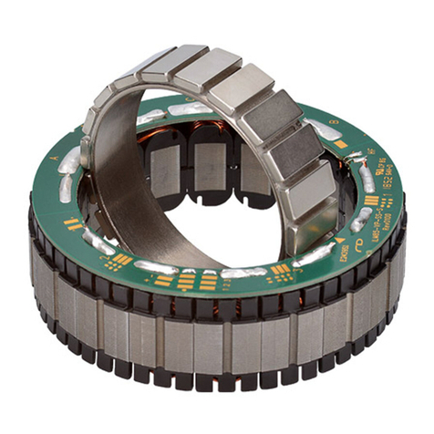
RoboDrive’s ILM series of stator-rotor installation
kits provides solutions for structurally integrated
drive engineering. An ILM (internal rotor motor)
servo kit consists of a cast stator and a rotor
with permanent magnets for installation in ma-
chines and devices in the commercial environ-
ment.
The RoboDrive technology provides the highest
power density at maximum torque and overload
capability in a compact design.
The flexible concept offers solutions for a variety
of demanding drive applications. Alternative
nominal currents, increased rotational speeds
and customised torque-speeds are available
upon request.
The implementation of customer-specific solutions to achieve a compact and thermal-
ly-optimized design is supported by extensive documentation and RoboDrive develop-
ment expertise.
ILM servo kits offer the following stand-out features:
—Installation kits for maximum freedom of design
—Hollow shaft capability
—Low voltage 12 V – 48 V
—Excellent copper fill factor offering high torque density and dynamic response
Fig. 1: ILM servo kit

Assembly Instructions | ILM Servo Kits
6 Edition 03/2021 EN
Introduction
—Concentrated windings for low losses
—Thermally-optimized actuator design thanks to structural integration and heat-con-
ducting epoxide casting resin
—Drive systems developed to optimize weight and installation space on the basis of
load profile analyses
—High bandwidth and minimal harmonics for optimal control quality
1.3 System components available from TQ-Drives
TQ-Drives RoboDrive is a complete drive technology supplier, offering the servo kit,
motors and motor-gearbox units right through to customised drive systems.
1.3.1 Example with system components for hollow shaft motors
Fig. 2: Example with system components for hollow shaft motors
1
2
3
4
Item Designation
1 Hollow shaft motor with integrated safety brake
2 ILM servo kit
3 Safety brake
4 Absolute position sensor

Assembly Instructions | ILM Servo Kits
7Edition 03/2021 EN
Introduction
1.3.2 Example with system components for solid shaft motors
Fig. 3: Example with system components for solid shaft motors
1
2
3
4
Item Designation
1 Solid shaft motor with integrated safety brake
2 ILM servo kit
3 Safety brake
4 Absolute position sensor
1.4 Revision index
Manual Edition Item no. Language
ILM Servo Kit Assembly Instructions 03/2021, second version 304188.0200 EN
Table 1: Revision index
1.5 Supplementary documents
Installation drawings are available for different sizes on our website.

Assembly Instructions | ILM Servo Kits
8 Edition 03/2021 EN
Introduction
1.6 Explanation of the symbols used
►This symbol indicates an action to be taken.
—This symbol indicates a list.
1.7 Training
The manufacturer offers training courses on the general handling of the ILM servo kits.
Please contact the TQ-Drives division of TQ-Systems GmbH as required.
1.8 Declaration of incorporation
The ILM servo kits are regarded as "partly-completed machinery" as defined in the
Machinery Directive 2006/42/EC. The declaration of incorporation is an integral part of
this installation manual (see section 8 on page 26).
1.9 Serial number
—The serial number is shown on the label attached to the stator.
—There is a tape with label and serial number attached to the rotor.
1.10 Warranty
TQ-Systems GmbH guarantees that, if used for the agreed purpose, the ILM servo kits
fulfil the contractually defined specifications and functionality and correspond to the
state of the art at the time of delivery.
The warranty is limited to material, manufacturing and processing defects.
The manufacturer’s liability and warranty shall not apply in the following cases:
—Genuine parts were not replaced with genuine parts or parts approved by
TQ-Systems GmbH.
—The assembly or set-up work was carried out without following these assembly
instructions or was otherwise carried out incorrectly.
—Unauthorized repairs
—Incorrect operation
—Incorrect use
—Application of force
—Other modifications to the contractual product
NOTE
The warranty period is 12 months and starts upon delivery to the customer.
Please contact the TQ-Drives division of TQ-Systems GmbH for all claims under the
warranty.

Assembly Instructions | ILM Servo Kits
9Edition 03/2021 EN
Introduction
1.11 Transportation and storage
—The stator and rotor of the ILM servo kit are shipped in separate packing units.
—Always transport the ILM servo kits in the original packaging to avoid mechanical
damage or damage due to static electricity.
—During transportation, avoid hard impacts or vibrations that could affect the
ILM servo kits.
1.12 Environmentally-friendly disposal
DANGER
Danger of death by powerful magnetic fields.
The life of persons with passive or active implants such as pacemakers, defibrillators, insu-
lin pumps etc. is put at risk if they stand in the vicinity of the ILM servo kit.
►Make sure that no persons who could possibly be affected by powerful magnetic fields
are able to approach the ILM servo kit. They must maintain a safe distance of at least
2 m.
►Instruct persons in the vicinity of the potential risk.
The ILM servo kits must not be disposed of in the residual waste bin.
►In Germany, metal and plastic components should be disposed of at the local recy-
cling centre. The national regulations in other EU states should also be followed.
►In Germany, electrical components should be disposed of in accordance with the
Electrical and Electronic Equipment Act (ElektroG). In other EU states, the na-
tional implementation of the Waste Electrical and Electronic Equipment Directive
2002/96/EC (WEEE) should be followed.
►The regulations and statutory requirements in your own country concerning disposal
should also be followed.
1.13 Trademarks
—HYSOL® is a trademark of Henkel.
—LOCTITE® is a trademark of Henkel.
—Kapton® is a trademark of DuPont.

Assembly Instructions | ILM Servo Kits
10 Edition 03/2021 EN
Safety
2 SAFETY
These instructions contain notes that you must follow for your own personal safety and
to avoid injury and damage to property. They are highlighted by warning triangles and
are shown as follows according to the level of danger.
2.1 Hazard classification
DANGER
The signal word designates a hazard with a high degree of risk which, if it is not avoided,
will result in death or severe injury.
WARNING
The signal word designates a hazard with a medium degree of risk which, if it is not avoid-
ed, will result in death or severe injury.
CAUTION
The signal word designates a hazard with a low degree of risk which, if it is not avoided,
could result in minor or moderate injury.
NOTE
A note as used in these instructions contains important information about the product or
about a part of the manual to which particular attention should be paid.
2.2 Target group
The activities described in this manual must only be carried out by technicians with the
following qualifications:
—Training in the installation and commissioning of electrical devices (qualified elec-
trician as defined in EN 50110–1: a person with technical training, knowledge and
experience sufficient to allow them to recognise and avoid the risks that might be
posed by electricity)
—Extensive knowledge in the fields of electrical engineering and drive technology
—Training in electrical and mechanical hazards and the local safety requirements
—Knowledge of the relevant standards and directives
—Knowledge and observance of this document and all the safety instructions
Any employee who does not have the relevant training must be given appropriate
training and instruction. The instruction is to be given by authorised personnel with the
appropriate training.

Assembly Instructions | ILM Servo Kits
11Edition 03/2021 EN
Safety
2.3 Intended use
The ILM servo kits must be used only for the applications listed in the technical descrip-
tions, i.e. as a structurally-integrated drive. Any different or more extensive usage will be
regarded as contrary to the intended use and will invalidate the warranty.
The ILM servo kits are regarded as "partly-completed machinery" as defined in the
Machinery Directive 2006/42/EC and must not be brought into service until it has been
determined that the machines in which the ILM servo kits are to be installed conform to
the provisions of the Machinery Directive 2006/42/EC.
The ILM servo kits are not domestic appliances; as components they are intend-
ed exclusively for reuse for commercial or professional purposes as defined by
IEC/EN 61000–3–2.
Intended use also includes compliance with this manual and the instructions it contains.
If the ILM servo kits are to be used safely and without interruption, they must have been
correctly transported, stored, assembled and set up.
For any use contrary to the intended use, TQ-Systems GmbH shall accept no liability for
any damage that may occur and offers no warranty that the product will work perfectly
and correctly.
2.4 Working environment and operation
The ILM servo kits must only be operated under the conditions of use and within the
performance limits specified in the documentation.
The ILM servo kits are not permitted to be used in the following areas:
—in potentially explosive areas
—in areas in which harmful substances as defined in EN 60721 may be encountered,
such as oils, acids, gases, vapours or dusts
—underwater
—in areas exposed to radiation
—in a vacuum

Assembly Instructions | ILM Servo Kits
12 Edition 03/2021 EN
Safety
2.5 Safety instructions for the ILM servo kit
DANGER
Danger of death by powerful magnetic fields.
The life of persons with passive or active implants such as pacemakers, defibrillators, insu-
lin pumps etc. is put at risk if they stand in the vicinity of the ILM servo kit.
►Make sure that no persons who could possibly be affected by powerful magnetic fields
are able to approach the ILM servo kit. They must maintain a safe distance of at least
2 m.
►Instruct persons in the vicinity of the potential risk.
►Attach warning instructions, stating POWERFUL MAGNETIC FIELDS at the installation
area and storage location.
—The rotors of the ILM servo kit will attract other magnetic materials. The forces of
attraction can be so great that the magnets of the servo kit splinter on impact and
tiny fragments fly into the eyes.
►Wear safety goggles to protect your eyes until you have finished installing the
ILM servo kit.
—If the ILM servo kit is operated below the specified temperature, the magnets can
become detached from the rotor and fly around due to thermal stressing of the
adhesive.
►Always operate the ILM servo kit within the specified temperature range.
—If the ILM servo kit operating voltage is too high, it will exceed the maximum permit-
ted rotational speed. There is a risk of parts becoming detached and flying around.
►Always operate the ILM servo kit within the specified voltage and speed ranges.
—The electromagnetic interference (EMI) emitted by the ILM servo kit is negligible in
nominal operation. However it is not possible to entirely exclude the possibility that
it will affect electrical devices.
—Fast acceleration of the ILM servo kit rotor can cause an inadequately secured
ILM servo kit to move suddenly and be flung out of its original position.
—The drive train that is connected to the ILM servo kit must be designed for the max-
imum rotational speed of the ILM servo kit, otherwise the drive train may be dam-
aged or crack.

Assembly Instructions | ILM Servo Kits
13Edition 03/2021 EN
Safety
—The ILM servo kit reaches high temperatures during operation. If there is a thermal
bridge between the housing and the ILM servo kit installed in it, there is a risk of
burns on the housing surface.
—Body parts (fingers, arms, hair, etc.) may be injured or torn off due to the rotation
of exposed mechanical parts such as motor shafts. There is also the risk that items
of clothing (ties, scarves, chains, rings, etc.) or objects (cables, etc.) may be wound
onto the motor shaft and injure the wearer.
►Never touch rotating components (motor shafts, clutches, etc.).
►Do not wear belts, chains, ties or clothing with wide sleeves at the workplace.
►Wear a hairnet if you have long hair.
►Make sure that there are no exposed rotating parts.
—Rotating shafts can crack and parts (such as screws, etc.) can be flung about.
►Secure rotating shafts with a protective cover.
—Install the ILM servo kit only in a dry environment.
—Protect the ILM servo kit against moisture and wet conditions.
2.6 Warning labels
►Attach warning labels that indicate the relevant risks to the machines in which the
ILM servo kits are installed.
►Make sure that the warning labels are always clearly identifiable.
►Replace any damaged warning labels.
►Replace any warning labels that are missing.

Assembly Instructions | ILM Servo Kits
14 Edition 03/2021 EN
Technical data
3 TECHNICAL DATA
3.1 Data sheet
You will find the technical data for the ILM servo kits in the data sheet provided in the
ILM servo kits download area.
3.2 Connection diagram (star-serial configuration)
Connections A, B and C can be found on the ILM servo kit.
A
B
C
U1
U2
L1
L3 L2
W1
W2
V1
V2
Fig. 4: Measuring points on the ILM servo kit (star-serial
configuration)
Measured variable Measured values
Nominal voltage Un* [V]
See data sheet in our
download area
Nominal current In* [A]
Terminal resistance
RTT* at 20 °C [m]
Terminal inductance
LTT * [H]
Table 2: Measuring points on the ILM servo kit (star-serial configuration)

Assembly Instructions | ILM Servo Kits
15Edition 03/2021 EN
Technical data
3.3 Installation dimensions
ILM
25×04
ILM
25×08
ILM
38×06
ILM
38×12
ILM
50×08
ILM
50×14
ILM
70×10
Outer diameter
stator D js8 [mm]
25 25 38 38 50 50 69
Board diameter
G [mm]
23.8 23.8 36.2 36.2 47.6 47.6 66.8
Winding head
diameter g [mm]
23.8 23.8 36 36 47.6 47.6 66
Stator length L [mm] 10.8 15.2 15.3 22.3 16.4 22.8 22.6
Inner diameter
rotor d H7 [mm]
11.6 11.6 18 18 30 30 42
Rotor length l [mm] 6.3 9.7 8.1 16.2 9.9 16.1 12.7
Table 3: Installation dimensions – part 1
ILM
70×18
ILM
85×04
ILM
85×13
ILM
85×23
ILM
85×26
ILM
115×25
ILM
115×50
Outer diameter
stator D js8 [mm]
69 85 85 85 85 115 115
Board diameter
G [mm]
66.8 82.8 82.8 82.8 82.8 111.8 111.8
Winding head
diameter g [mm]
66 81 81 81 81 110 110
Stator length L [mm] 30.5 17.6 27.2 37.2 40.7 39.0 68.4
Inner diameter
rotor d H7 [mm]
42 52 52 52 52 74 74
Rotor length l [mm] 20.7 7.1 15.7 25.1 27.2 27.1 54.2
Table 4: Installation dimensions – part 2
L
D
G
d
g
l
Fig. 5: Dimension designations

Assembly Instructions | ILM Servo Kits
16 Edition 03/2021 EN
ILM servo kit configurations
4 ILM SERVO KIT CONFIGURATIONS
4.1 Basic servo kit with connection board
Possible configurations:
—Star-serial
—Star-parallel
—Delta-serial
—Delta-parallel
A temperature sensor is included as standard.
4.2 Servo kit with Hall commutation
Basic servo kit with:
—Digital Hall elements
—Extended rotor
4.3 Servo kit with three pins on the stator
The servo kit without connection board is available
with three pins on the stator as a custom solution.
Possible configurations:
—Star-serial
Fig. 6: Basic servo kit with
connection board
Fig. 7: Servo kit with Hall
commutation
Fig. 8: Servo kit with three pins on
the stator

Assembly Instructions | ILM Servo Kits
17Edition 03/2021 EN
Solder pads on the connection board
5 SOLDER PADS ON THE CONNECTION BOARD
Fig. 9 shows the solder pads on the connection board by way of example.
Detailed drawings for your type of ILM servo kit are available on our website.
Fig. 9: Solder pads on the connection board
Notch
Notch
Phase A
Phase C
Phase B
A
Detail ATemperature sensor 2
SP2–2
SP2–1
5 V voltage supply
GND
VCC 5 V
Hall sensors 1/2/3
SA3
SA2
SA1
Temperature sensor 1
SP1–2
SP1–1

Assembly Instructions | ILM Servo Kits
18 Edition 03/2021 EN
Reference design for ILM servo kits
6 REFERENCE DESIGN FOR ILM SERVO KITS
Fig. 10 shows a reference design with installation notes for integrating the ILM servo kit.
The design specifications for the specific type of ILM servo kit are contained in the
“Drawing ILM XXxXX” drawings which are available on our website. Joining of the rotor
and shaft or stator and housing can also be carried out by TQ-Drives, if required.
Stator
Rotor shell with
magnets
Hollow or solid shaft,
concentricity and
radial runout 0.02 mm
Bonding rotor
and shaft
Bonding the stator with
thermally-conductive
adhesive
Adhesive injection hole,
Ø 0.9 mm
Leave 8 to 10 mm
clearance for wiring
Be aware of the
effect of the
motor’s magnetic
field on encoders
with magnetic code
wheels.
Design specifications
as shown in the
"MEBS XX-YY Installation“
drawing
Keep this area clear to prevent
magnetic eddy current losses
Fig. 10: Reference design for ILM servo kits

Assembly Instructions | ILM Servo Kits
19Edition 03/2021 EN
Assembly
7 ASSEMBLY
DANGER
Danger of death by powerful magnetic fields.
The life of persons with passive or active implants such as pacemakers, defibrillators, insu-
lin pumps etc. is put at risk if they stand in the vicinity of the ILM servo kit.
►Make sure that no persons who could possibly be affected by powerful magnetic fields
are able to approach the ILM servo kit. They must maintain a safe distance of at least
2 m.
►Instruct persons in the vicinity of the potential risk.
►Attach warning instructions stating POWERFUL MAGNETIC FIELDS to the packaging, at
the installation area and at the storage location.
DANGER
Danger of death by electric shock.
The ILM servo kit is supplied with electrical voltage for operation. Touching live conductors
can result in death or severe injuries.
►Use the main switch to switch off all power to the complete system before starting
installation or maintenance work.
►Observe the five safety rules (DIN VDE 0105–100) for working on electrical systems:
—Disconnect from mains (all-pole disconnection of a system from live parts)
—Secure against reconnection
—Check that the system is voltage-free
—Earth and short-circuit
—Cover or block off access to adjacent live parts

Assembly Instructions | ILM Servo Kits
20 Edition 03/2021 EN
Assembly
DANGER
Danger of death by electric shock or arcing at the power connections of the
ILM servo kit
The contacts of the power connections carry potentially fatal voltages and high current
strengths. Removing the cables to the power connections of the ILM servo kit during oper-
ation can cause arcing, resulting in serious or fatal injury.
Depending on the installed buffer capacity, the DC link of a connected inverter can contin-
ue to carry dangerous voltages for some time, even after the power supply to the entire
system is switched off.
►Never detach electrical connections on the ILM servo kit or the inverter while they are
live.
►Use a permitted meter to check that the power connections are voltage-free before
you carry out installation work on the device.
WARNING
Danger of eye injuries caused by splintering magnetic parts
The rotors of the ILM servo kit will attract other magnetic materials. The forces of attraction
can be so great that the magnets of the servo kit splinter on impact and tiny fragments fly
into the eyes.
►Wear safety goggles to protect your eyes until you have finished installing the
ILM servo kit.
►Keep the rotors of the ILM servo kit away from other magnetic materials.
This manual suits for next models
14
Table of contents
Other TQ Servo Drive manuals
Popular Servo Drive manuals by other brands
YASKAWA
YASKAWA E7LVD002 Technical manual
Glentek
Glentek SMB9675-1A-1-7700 Installation & operation manual
Metronix
Metronix DIS-2 310/2 FB FS STO product manual
Servotronix
Servotronix CDHD Reference manual
Panasonic
Panasonic MINAS A6 Series quick start guide
adept technology
adept technology MotionBlox-10 installation guide
