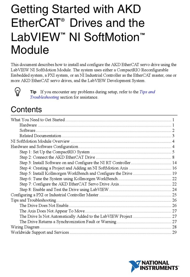
National Instruments NI 9505 User manual
Other National Instruments Servo Drive manuals

National Instruments
National Instruments NI 9505 User manual

National Instruments
National Instruments NI 9516 User manual

National Instruments
National Instruments AKD EtherCAT User manual

National Instruments
National Instruments NI 9505E User manual

National Instruments
National Instruments NI 9514 User manual

National Instruments
National Instruments NI 9512 C Series User manual

National Instruments
National Instruments NI 9516 User manual

National Instruments
National Instruments NI 9502 User manual
Popular Servo Drive manuals by other brands

Lenze
Lenze m850 Mounting and switch-on instructions

Baumuller
Baumuller b maXX 3000 Instruction handbook

Baumuller
Baumuller b maXX 5000 Instruction handbook

Baumuller
Baumuller b maXX 5500 Instruction handbook

Danfoss
Danfoss VLT HVAC Drive FC 102 operating instructions

Omron
Omron CK5M-CPU 1 Series Startup guide


