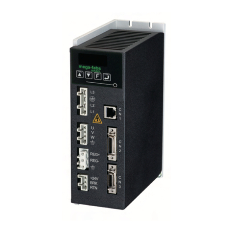
Megmeet M5-N Series User manual

1
M5-N Series Servo System
User Manual
Document Version: V1.0
Archive Date: 2023/12/14
BOM Code:
Shenzhen Megmeet Electric Co., Ltd. provides full technical support for our
customers,customers can contact local Megmeet offices or customer service centers, or
directly contact Megmeet headquarters.
Shenzhen Megmeet Electric Co., Ltd.
All rights reserved. The contents in this document are subject to change without notice.
Shenzhen Megmeet Electric Co., Ltd.
Address: 5th Floor, Block B, Unisplendor Information Harbor, Langshan Rd., Science &
Technology Park, Nanshan District, Shenzhen, 518057, China
Website: www.megmeet.com
Tel: +86-755-86600500
Fax: +86-755-86600562
Service Email: driveservice@megmeet.com
Customer Service Tel: +86-400-666-2163

2
Foreword
Thank you for choosing the M5-N series servo system of Shenzhen Megmeet Electric Co., Ltd.
M5-N servo system use a new hardware design platform and a new generation of control algorithms, this series
of drive with excellent performance, perfect function, compact structure, convenient installation, simple
debugging, easy maintenance, is the cost-effective products for drive generic and OEM markets. This series of
servo supports EtherCAT communication protocol and can realize network operation of multiple sets of servo
systems with the host computer. With the functions of rigid table setting, inertia identification and oscillation
suppression, making the servo easy to use, it is applicable for machine tool, robot, semiconductor, glass
manufacturing, lithium battery equipment, woodworking machinery, textile machinery, packaging machinery,
spraying machinery and other industries, realizing rapid and accurate position,speed and torque control.
M5-N servo system can realize high mechanical time constant and stable operation together with medium inertia
servo motor. This series of servo supports absolute encoder.
The relevant precautions during the installation, wiring, parameter setting, troubleshooting and daily maintenance
will be detailed in this manual. To ensure the correct installation and operation of the M5-N series servo system
as well as its high performance, please read carefully this user manual before installing the equipment. This
manual shall be kept properly and delivered to the actual users of the drive.
Precautions for unpacking inspection
Please check carefully when unpacking the product:
·Whether the product has the damage signs;
·Whether the rotating shaft of the servo motor rotates smoothly(except for motor with brake);
·Whether the rated value in the nameplate is consistent with your order requirement;
·Whether the wiring is damaged and whether the wiring can be used.
We have implemented strict inspection on the manufacturing, package and delivery of the product. If there is any
error, please contact us or your distributor immediately.
We are engaged in the continuous improvement of drive. The relevant manuals provided by us are subject to
change without prior notice.

3
Safety Precautions
Operation without following instructions can cause death or severe personal injury.
Operation without following instructions can cause medium or slight personal injury or
damage to the product and other equipment.
◆Please install the product on the incombustible materials (e.g., metal), otherwise, fire may be caused.
◆Do not place any combustible material near the product, otherwise, fire may be caused.
◆Do not install the product in the environment with explosive gas, otherwise, explosion may be caused.
◆Only qualified personnel can wire the drive, otherwise, electric shock may be caused.
◆Never wire the drive unless the input AC supply is completely disconnected, otherwise, electric shock
may be caused.
◆The grounding terminal of the drive must be reliably grounded, otherwise, electric shock may be caused.
◆The cover must be properly closed before power up, otherwise, electric shock and explosion may be
caused.
◆When powering up the drive that has been stored for over 2 years, the input voltage must be gradually
increased with the voltage regulator, otherwise, electric shock and explosion may be caused.
◆Do not touch the terminals when the product is powered up, otherwise, electric shock may be caused.
◆Do not operate the drive with wet hands, otherwise, electric shock may be caused.
◆Maintenance operation can not be conducted until 10 minutes has passed after disconnecting the power
supply. Meanwhile, be sure to confirm that the charge LED is completely off and the DC bus voltage is
below 36V, otherwise, electric shock may be caused.
◆Only qualified personnel can replace the components. Do not leave any wire or metal parts inside the
drive, otherwise, fire may be caused.
◆The bare parts of the terminal lugs in the main circuit must be wrapped with insulation tape, otherwise,
electric shock may be caused.
◆Please install the drive on the place that can withstand the weight of the drive, otherwise, the drive may
drop and cause human injury or property damage.
◆Do not install the drive in the environment with water splash (e.g., near the water pipe), otherwise, you
may suffer the property loss.
◆Take care not to drop any foreign objects, such as the screws, gaskets and metal bars, into the drive,
otherwise, fire and property damage may be caused.
◆Do not install and operate the drive if it is damaged or its components are not complete, otherwise, fire
and human injury may be caused.

4
◆Do not install the product in the place exposed to direct sunlight, otherwise, property damage may be
caused.
◆Cable lugs must be firmly connected to the terminals of main circuit, otherwise, property damage may
be caused.
◆When removing the servo motor, we can not just pull the cable or hold the rotating shaft to pull the
motor, otherwise, the motor may drop and cause human injury or property damage.
◆Do not directly strike the axis core, for example: tap or beat, this may cause the axis core and the
encoder attached to the opposite side of the axis damaged, otherwise, property damage may be
caused.
◆Do not store the servo motor in the place that exceeds predetermined vibration, otherwise, property
damage may be caused.

5
Contents
M5-N Series Servo System .......................................................................................................1
Chapter 1 M5-N Servo System Selection ................................................................................. 8
1.1 Servo motor and drive model ..........................................................................................................................8
1.2 Servo system configuration specifications ...................................................................................................12
1.3 Applicative cables and models ..................................................................................................................... 12
Chapter 2 Servo System Specifications ..................................................................................15
2.1 Servo drive standard specifications ............................................................................................................. 15
2.2 Servo motor standard specifications ............................................................................................................17
2.3 Servo drive dimensions .................................................................................................................................18
2.4 Servo motor dimensions and interface definition ........................................................................................ 19
Chapter 3 Installation Description ........................................................................................... 22
3.1 Servo drive installation ..................................................................................................................................22
3.1.1 Installation site .........................................................................................................................................................22
3.1.2 Installation environment requirements .................................................................................................................... 22
3.1.3 Servo drive installation precautions .........................................................................................................................22
3.2 Servo motor installation ................................................................................................................................ 24
3.2.1 Installation site .........................................................................................................................................................24
3.2.2 Installation environment requirements .................................................................................................................... 24
3.3 System wiring diagram ..................................................................................................................................25
3.4 Recommended specifications for circuit breakers and fuses ..................................................................... 27
3.5 Related specifications of braking resistor .................................................................................................... 27
Chapter 4 Wiring of Servo System ..........................................................................................28
4.1 Servo drive main circuit connection ............................................................................................................. 29
4.1.1 Main circuit specifications ........................................................................................................................................29
4.1.2 Main circuit cable dimensions ................................................................................................................................. 29
4.2 Servo motor encoder signal connection (CN2) ............................................................................................30
4.3 Control signal interface definition ................................................................................................................. 31
4.3.1 Digital input and output signals ............................................................................................................................... 31
4.4 Communication port wiring ........................................................................................................................... 35
Chapter 5 Operation Panel ..................................................................................................... 36
5.1 Interface introduction .....................................................................................................................................36
5.2 Working status display .................................................................................................................................. 37
5.3 Working status display and parameter setting flowchart .............................................................................37
5.4 Parameter value display ............................................................................................................................... 38
Chapter 6 Commissioning Instructions ................................................................................... 39

6
6.1 Check before running ....................................................................................................................................39
6.2 Commissioning ..............................................................................................................................................39
6.3 Electronic gear ...............................................................................................................................................40
6.4 Brake settings ................................................................................................................................................44
6.4.1 Servo motor brake wiring diagram .......................................................................................................................... 44
6.4.2 Brake timing ............................................................................................................................................................ 44
6.4.3The brake timing when the servo motor is stationary ...............................................................................................44
6.4.4 The brake timing when the servo motor is rotating ................................................................................................. 46
6.4.5 Servo drive fault status brake timing ....................................................................................................................... 48
Chapter 7 EtherCAT Communication ......................................................................................49
7.1 Overview of EtherCAT bus ........................................................................................................................... 49
7.2 M5-N drive bus function introduction ............................................................................................................49
7.2.1 M5-N communication specifications ........................................................................................................................49
7.2.2 EtherCAT Network reference model ........................................................................................................................50
7.2.3 EtherCAT network state machine ............................................................................................................................51
7.2.4 Process Data PDO .................................................................................................................................................. 52
7.2.5 Mailbox data SDO ................................................................................................................................................... 53
7.2.6 Distributed Clock (DC) .............................................................................................................................................54
7.3 CiA402 Device Control (Device Protocol) ....................................................................................................54
7.3.1 CoE state machine .................................................................................................................................................. 54
7.3.2 Object dictionary ......................................................................................................................................................56
7.3.3 Device control word and status word ...................................................................................................................... 56
7.3.4 Common conversion factor ..................................................................................................................................... 59
7.4 Bus operation mode ...................................................................................................................................... 60
7.4.1 Profile Position Mode .............................................................................................................................................. 61
7.4.2 Profile Velocity Mode ............................................................................................................................................... 64
7.4.3 Profile Torque Mode ................................................................................................................................................ 67
7.4.4 Homing Mode .......................................................................................................................................................... 70
7.4.5 Cyclic Synchronous Position Mode ....................................................................................................................... 102
7.4.6 Cyclic Synchronous Velocity Mode ....................................................................................................................... 104
7.4.7 Cyclic Synchronous Torque Mode.........................................................................................................................106
Chapter 8 Drive Parameter Object ........................................................................................ 110
8.1 M5-N Drive parameters ...............................................................................................................................110
Index 2000h(P00): Drive parameters ............................................................................................................................. 110
Index 2001h(P01): Servo motor parameters .................................................................................................................. 111
Index 2002h(P02): Basic control parameters ................................................................................................................. 113
Index 2003h(P03): Digital input and output terminal parameters ................................................................................... 116
Index 2005h(P05): Position control parameters ............................................................................................................. 120
Index 2006h(P06): Speed control parameters ............................................................................................................... 125
Index 2007h(P07): Torque control parameters ...............................................................................................................127

7
Index 2008h(P08): Gain parameters .............................................................................................................................. 129
Index 2009h(P09): Adjustment parameters ....................................................................................................................131
Index 200Ah(P10): Fault and protection parameters ..................................................................................................... 135
Index 200Bh(P11): Display parameters ......................................................................................................................... 143
Index 200Ch(P12): Servo positioning parameters ......................................................................................................... 147
Index 2011h(P17): EtherCAT communication parameters ............................................................................................ 150
Index 2012h(P18): Advanced parameters ......................................................................................................................153
Index 2014h(P20): Bus configuration group parameters ............................................................................................... 153
8.2 Slave station address assignment function ............................................................................................... 154
8.3 User unit selection .......................................................................................................................................154
8.3.1 Position user unit ................................................................................................................................................... 154
8.3.2 Speed user unit ..................................................................................................................................................... 154
8.3.3 Torque user unit .................................................................................................................................................... 154
Chapter 9 Troubleshooting ....................................................................................................155
Appendix 1 Warranty and Service .........................................................................................167

Chapter 1 M5-N Servo System Selection
8
Chapter 1 M5-N Servo System Selection
1.1 Servo motor and drive model
1.Servo motor model
Fig.1-1 M5-N servo motor model
2.Servo motor nameplate
Fig.1-2 M5-N servo motor nameplate
SPM-SC80401MAK-L
SPM-SC80401MAK-L

Chapter 1 M5-N Servo System Selection
9
3.Servo drive model
Fig.1-3 M5-N servo drive model
4.Servo drive nameplate
Fig.1-4 M5-N servo drive nameplate

Chapter 1 M5-N Servo System Selection
10
5.The name and introduction of each part of the servo drive
Fig.1-5 Schematic diagram of each part of M5-N servo drive (SIZEA)
Table 1-1 Description of each part of M5-N servo drive (SIZEA)
No.
Name
Description
①
CN3, CN4
Communication interface
Two RJ45 ports for EtherCAT communication
②
CN5
Type-C USB
communication port
Connect the USB of the computer through this port, you can adjust the
parameters of the drive and debug the performance.
③
LED digital tube
5-digit 8-segment digital tube for status monitoring, parameter display and
setting.
④
Operation keys
5 keys for parameter adjustment and display status switching, etc.
⑤
CN1
Control IO interface
DB15 female connector, control IO interface, used to connect with external IO
and host controller.
⑥
CN2
Encoder interface
1394 female connector for connecting motor encoder
⑦
CHARGE
Bus power indicator
It is used to indicate the state of the bus power. The indicator light indicates
that the capacitor of the bus is charged. Do not touch the power terminal even
if the main power supply is cut off to avoid electric shock.
⑧
Main
circuit
terminal
L1, L2
Main power
supply input
Main power supply input, single-phase 220V.
○—, P
DC bus
terminal
DC bus terminal for common bus connection
P, PB
Braking resistor wiring terminals, connect between P and PB for external
①
②
④
③
⑤
⑥
⑦
⑧
⑨

Chapter 1 M5-N Servo System Selection
11
Brake resistor
wiring terminal
braking resistors.
U, V, W
Servo motor
power
terminals
Servo motor UVW power terminal
PE
Motor ground terminal.
⑨
Ground terminal
Power ground terminal.
Fig.1-6 Schematic diagram of each part of M5-N servo drive (SIZEB)
Table 1-2 Description of each part of M5-N servo drive (SIZEB)
No.
Name
Description
①
CN3, CN4
Communication interface
Two RJ45 ports for EtherCAT communication
②
CN5
Type-C USB
communication port
Connect the USB of the computer through this port, you can adjust the
parameters of the drive and debug the performance.
③
LED digital tube
5-digit 8-segment digital tube for status monitoring, parameter display and
setting.
④
Operation keys
5 keys for parameter adjustment and display status switching, etc.
⑤
CN1
Control IO interface
DB15 female connector, control IO interface, used to connect with external IO
and host controller.
⑥
CN2
Encoder interface
1394 female connector for connecting motor encoder
⑦
CHARGE
It is used to indicate the state of the bus power. The indicator light indicates
①
②
④
③
⑤
⑥
⑦
⑧
⑨

Chapter 1 M5-N Servo System Selection
12
Bus power indicator
that the capacitor of the bus is charged. Do not touch the power terminal even
if the main power supply is cut off to avoid electric shock.
⑧
Main
circuit
terminal
L1, L2, L3
Main power
supply input
Main power supply input, three-phase 220V.
○—, P
DC bus
terminal
DC bus terminal for common bus connection
P, PB, IR
Brake resistor
wiring terminal
Braking resistor wiring terminals, please short-circuit PB and IR for internal
braking resistors; connect between P and PB for external braking resistors.
U, V, W
Servo motor
power
terminals
Servo motor UVW power terminal
PE
Motor ground terminal.
⑨
Ground terminal
Power ground terminal.
1.2 Servo system configuration specifications
Table 1-3 Servo motor configuration specification table
Voltage
Rated
speed
(rpm)
Maximum
speed
(rpm)
Power
(W)
Motor model
Rated
torque
(N.m)
Motor
frame
number
Matching
drive model
Drive
SIZE
220V
3000
6000
100
SPM-SC*0401M**-L
0.32
40
M5-NS1R6A
A
6500
200
SPM-SC*0602M**-L
0.64
60
M5-NS1R6A
A
5000
400
SPM-SC*0604M**-L
1.27
60
M5-NS2R8A
A
5000
750
SPM-SC*0807M**-L
2.39
80
M5-NS5R5A
B
5000
1000
SPM-SC*0810M**-L
3.19
80
M5-NS7R6A
B
1.3 Applicative cables and models
The model descriptions of the servo system power cable and encoder cable are shown in Fig. 1-7 and Fig. 1-8.
Fig.1-7 Power cable model description

Chapter 1 M5-N Servo System Selection
13
Fig.1-8 Encoder cable model description
Servo system cable options and their descriptions are shown in Table 1-4 and Table 1-5.
Table 1-4 Servo system cable options
Name
Model
Appearance
40
servo system
motor power
cable
SPL-MZ01--M5-xx-x
60/80
servo system
motor power
cable
SPL-MA04-M5--xx-x
40/60/80
servo system
multi-turn
absolute
encoder cable
SPL-E01-M5-xx-x
40/60/80
servo system
single-turn
absolute
encoder cable
SPL-E05-M5-xx-x

Chapter 1 M5-N Servo System Selection
14
Table 1-5 Cable description
No.
Model
Name
Description
Cable
diameter
(mm2)
1
SPL-MZ01-M5-xx-x
Main motor
cable (40 base)
Main motor cable, motor side Amp female connector
0.25
2
SPL-MA04-M5-xx-x
Main motor
cable (60/80
base)
Main motor cable, motor side Amp female connector
0.75
8
SPL-E01-M5-xx-x
Multi-turn
absolute
encoder cable
Drive side 6-pin male connector, motor side 9-pin Amp
female connector (with battery case)
—
9
SPL-E05-M5-xx-x
Single-turn
absolute
encoder cable
Drive side 6-pin male connector, motor side 9-pin Amp
female connector (without battery case)
—

Chapter 2 Servo System Specifications
15
Chapter 2 Servo System Specifications
2.1 Servo drive standard specifications
2.1.1 Servo drive electrical specifications
Table 2-1 Drive list and electrical specifications
Voltage level
220V
Model
M5-NS1R6A
M5-NS2R8A
M5-NS5R5A
M5-NS7R6A
Power level
200W
400W
750W
1kW
Outline
SIZE A
SIZE B
Phase
Single phase
Single/three phase
Rated input
current (A)
2.3
4
7.6/3.7
9.6/5.1
Rated output
current (A)
1.6
2.8
5.5
7.6
Maximum output
current (A)
5.8
9.3
16.9
20
Main circuit power
supply
200~240V, -10%~+10%, 50/60HZ
Braking resistor
No built-in
braking resistor
Built-in
braking resistor
2.1.2 Servo drive basic specifications
Table 2-2 Servo drive basic specifications
Basic specifications
Basic
specifications
Control mode
IGBT, PWM control, sine wave current drive mode
Encoder
Rotating
motor
Absolute encoder
Control IO
DI
Different
functions
configured
according
to parameters
5 general inputs, optocoupler isolation, NPN and PNP inputs can be
selected
Input voltage range 20~30V, input impedance 3.9K
DO
Different
functions
configured
according
to parameters
3 general outputs, optocoupler isolation, NPN and PNP output can be
selected
Maximum operating voltage 30V, maximum current 100mA

Chapter 2 Servo System Specifications
16
Communication
function
RS485
Support MODBUS communication protocol, only M5-P, M5-C series support
CAN
Support CANopen communication protocol, follow CiA402 profile, only M5-C series
support
EtherCAT
Support CoE and SoE communication protocol, follow CiA402 profile, only M5-N series
support
USB
Connect the computer and the servo drive to debug and adjust the servo
Other
ports
Button
5 buttons
LED display
5 8-segment LED display
Power indicator
CHARGE lamp
STO safety function
General safety STO function, optional, only M5-N series support
General function
Auto-adjust
The host computer issues an action command, drives the motor to run, estimates and
determines the load rotational inertia ratio in real time, and automatically sets the rigidity
level
Multi-control mode
switching
Position mode, speed mode, torque mode, position/speed mode switching, speed/torque
mode switching, position/torque mode switching, EtherCAT mode.
Protection function
Overvoltage, undervoltage, overcurren,t overspeed, stall, overheat, overload, encoder
abnormality, input phase loss, excessive position deviation
High frequency
vibration
suppression
4 sets of traps suppress the vibration frequency of 100~2000Hz
End vibration
suppression
2 sets of filters suppress the end low frequency vibration of 1~100Hz
Homing mode
Multiple homing functions
Reverse clearance
compensation
Function to improve the response delay that occurs when the direction of travel of the
machine is reversed
Mechanical analyzer
function
Analyze the frequency characteristics of the mechanical system through the host
computer software
Inertia identification
Offline and online system inertia identification
Torque observer
Load torque observation and compensation
Electronic cam
512 point electronic cam curve
Friction
compensation
Compensate system friction
Position
control
Control input
Deviation counter clearing, electronic gear switching, etc.
Control output
Positioning completed
Position reference
EtherCAT
Electronic gear
4 sets of electronic gear ratio/on line
Speed control
Performance
Speed variation
rate
Load variation
rate
0~100% load: below 0.5% (at rated speed)
Voltage
variation rate
Rated voltage ±10%: 0.5% (at rated speed)
Temperature
variation rate
25±25 ℃: below 0.5% (at rated speed)
Speed control
range
1~5000
Speed loop
response
characteristics
2kHz
Soft start time
0~6000ms
Control input
Internal speed command selection 1/2/3, zero speed clamp, etc.
Control output
Speed arrival etc.

Chapter 2 Servo System Specifications
17
Torque control
Performance
Torque control
accuracy
±1%
Frequency
characteristics
3kHz
Control input
Zero speed clamp, torque command symbol input, etc.
Control output
Speed arrival etc.
Speed limit function
The speed limit value can be set according to the parameters
2.2 Servo motor standard specifications
2.2.1 Servo motor basic specifications
Table 2-3 General basic specifications of servo motors
Servo motor basic index items
Protection degree
IP65
Ambient temperature
0℃~+40℃
Ambient humidity
Relative humidity <90% (no frost condition)
Installation method
Flange mounted
Insulation resistance
50MΩ (500V)
Insulation voltage
1500V (220V motor)
1800V (380V motor)
Insulation class
F
2.2.2 Servo motor rated specifications
Table 2-4 Servo motor standard specifications
Motor model
Rated
voltage
(V)
Rated
power
(kW)
Rated
speed
(RPM)
Maximum
speed
(RPM)
Rated
torque
(N.m)
Peak
torque
(N.m)
Rated
current
(A)
Peak
current
(A)
Rotor inertia
(10-4kg.m2)
SPM-SC*0401M**-L
220
0.1
3000
6000
0.32
0.95
0.92
2.85
0.062(0.072)
SPM-SC*0602M**-L
220
0.2
3000
6500
0.64
1.91
1.5
4.66
0.28(0.3)
SPM-SC*0604M**-L
220
0.4
3000
5000
1.27
3.81
2.1
6.5
0.56(0.58)
SPM-SC*0807M**-L
220
0.75
3000
5000
2.39
7.17
4.1
13.4
1.5(1.65)
SPM-SC*0810M**-L
220
1
3000
5000
3.19
9.56
5.7
17.7
2(2.15)
Note: Parameters in parenthesis is the parameter of the motor with brake.

Chapter 2 Servo System Specifications
18
2.3 Servo drive dimensions
1.SIZE A (Applicable drive: M5-NS1R6A, M5-NS2R8A)
Fig.2-1 Dimensions for servo drive of SIZE A
2.SIZE B (Applicable drive: M5-NS5R5A, M5-NS7R6A)
Fig.2-2 Dimensions for servo drive of SIZE B

Chapter 2 Servo System Specifications
19
2.4 Servo motor dimensions and interface definition
1. 40 base medium inertia servo motor
(1) Dimensions
Key
S lo t
Fig.2-3 Dimensions for 40 base medium inertia servo motor
Table 2-5 Dimensions for 40 base medium inertia servo motor
Model
L(mm)
SPM-SC*0401M**-L
67.7(95)
Note: Dimensions in parentheses is the dimension of the motor with brake.
(2) Interface definition
Fig.2-4 Interface definition for 40 base medium inertia servo motor
Motor connection
specifications
Pin
Signal
1
U
2
W
3
V
4
PE
Motor with brake
connection
specifications
Pin
Signal
1
+
2
-
Absolute encoder
connection specifications
Pin
Signal
1
PE
2
5V
3
GND
4
SD+
5
SD-
6
E+
7
E-

Chapter 2 Servo System Specifications
20
2. 60 base medium inertia servo motor
(1) Dimensions
Fig.2-5 Dimensions for 60 base medium inertia servo motor
Table 2-6 Dimensions for 60 base medium inertia servo motor
Model
L(mm)
SPM-SC*0602M**-L
71.8(101)
SPM-SC*0604M**-L
88.8(118.1)
Note: Dimensions in parentheses is the dimension of the motor with brake.
(2) Interface definition
Fig.2-6 Interface definition for 60 base medium inertia servo motor
Motor connection
specifications
Pin
Signal
1
U
2
W
3
V
4
PE
Motor with brake
connection
specifications
Pin
Signal
1
+
2
-
Absolute encoder
connection specifications
Pin
Signal
1
PE
2
5V
3
GND
4
SD+
5
SD-
6
E+
7
E-
This manual suits for next models
4
Table of contents
Other Megmeet Servo Drive manuals
Popular Servo Drive manuals by other brands
Motor Power Company
Motor Power Company DUET AD Series Reference manual
Honeywell
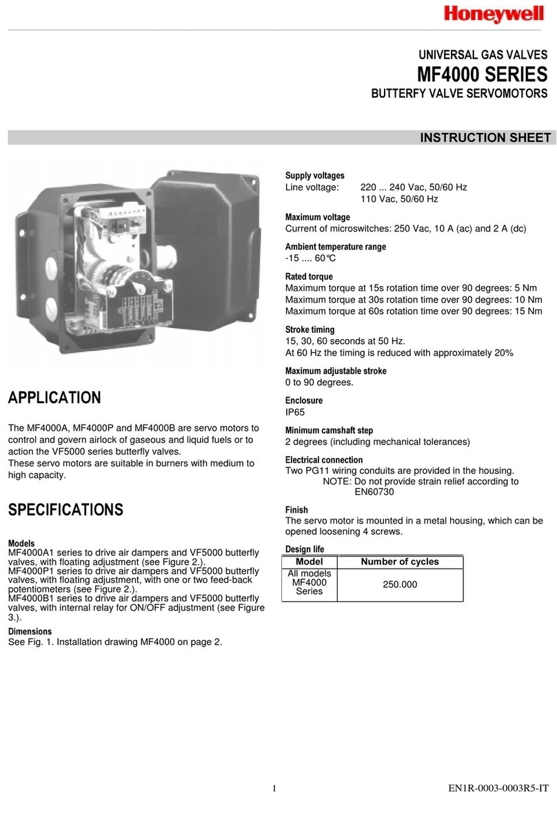
Honeywell MF4000 Series instruction sheet
Higen
Higen FDA5000 Series Operation manual
Leadshine
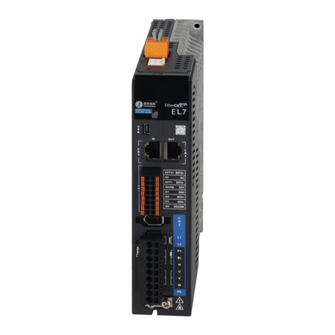
Leadshine EL7-EC Series user manual
HPI Racing
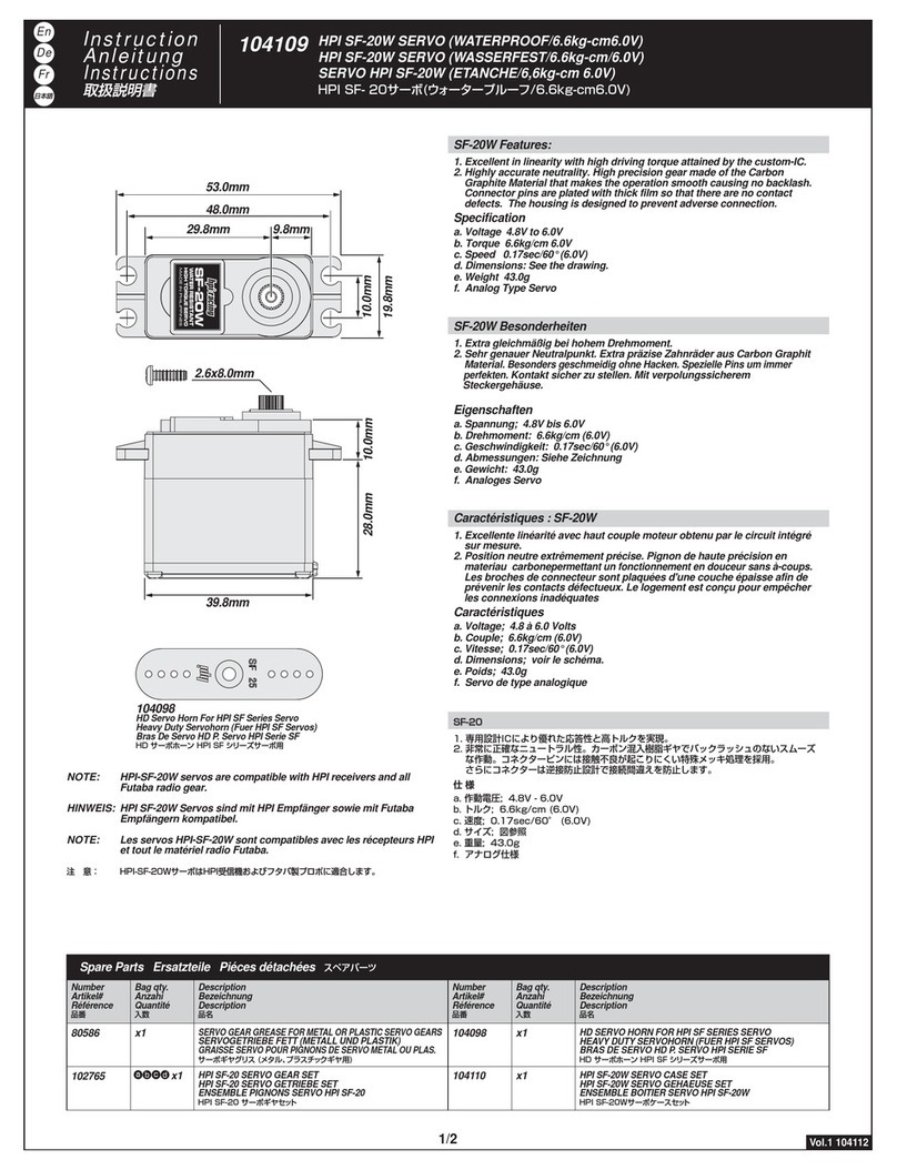
HPI Racing SF-20W instruction manual
Rockwell Automation
Rockwell Automation Allen-Bradley Ultra3000 manual
