Track Systems Traqmate User manual

Traqmate
GPS Data Acquisition System
User Manual
Version 1.02 June 14, 2005
Copyright © 2005 Track Systems Technologies, LLC
Traqmate, Traqview, and the track systems logo are
trademarks of track systems technologies, llc
Microsoft and windows are trademarks of Microsoft corp.
Velcro is a trademark of Velcro Industries B.V.

Traqmate User Manual V1.02 June 14, 2005
Copyright © 2005 Track Systems Technologies, LLC Page 2
This page intentionally left blank.

Traqmate User Manual V1.02 June 14, 2005
Copyright © 2005 Track Systems Technologies, LLC Page 3
Table of Contents
WELCOME TO TEAM TRAQMATE............................................................................................... 4
SYSTEM OVERVIEW ..................................................................................................................... 5
TRAQMATE FEATURES.................................................................................................................... 5
TRAQMATE SYSTEM COMPONENTS ................................................................................................. 6
TRAQMATE SYSTEM PACKAGES ...................................................................................................... 8
TRAQVIEW SOFTWARE INSTALLATION.................................................................................... 9
TRAQVIEW ANALYSIS SOFTWARE .................................................................................................... 9
USB DRIVER ................................................................................................................................. 9
TRAQMATE INSTALLATION....................................................................................................... 10
SENSOR UNIT INSTALLATION......................................................................................................... 10
SENSOR AND DISPLAY UNIT OPERATION........................................................................................ 11
SENSOR UNIT ONLY OPERATION ................................................................................................... 11
GPS ANTENNA PLACEMENT ......................................................................................................... 11
CONNECTING A SENSOR UNIT TO A DISPLAY UNIT.......................................................................... 11
POWER CONNECTION................................................................................................................... 12
TRAQMATE DISPLAY UNIT INSTALLATION ....................................................................................... 13
TRAQMATE BASIC...................................................................................................................... 15
SYSTEM DESCRIPTION.................................................................................................................. 15
CONTROLS................................................................................................................................... 15
TRAQMATE COMPLETE............................................................................................................. 16
SYSTEM DESCRIPTION.................................................................................................................. 16
CONTROLS................................................................................................................................... 16
MENU SYSTEM............................................................................................................................. 17
FEATURES ................................................................................................................................... 18
TRAQVIEW ANALYSIS AND CONFIGURATION PROGRAM.................................................... 20
TOOLBAR BUTTONS AND CONTROLS ............................................................................................. 20
MENU OPTIONS............................................................................................................................ 20
FILES........................................................................................................................................... 21
VIEWING OPTIONS........................................................................................................................ 21
EXCHANGING INFORMATION WITH TRAQMATE ................................................................................ 22
UNIT INFO SCREEN....................................................................................................................... 23
ANALYSIS TOOLS.......................................................................................................................... 25
USING TRAQMATE FOR ANALYSIS.......................................................................................... 32
DRIVER COMPARISON................................................................................................................... 32
VEHICLE PERFORMANCE COMPARISON ......................................................................................... 36
SAFETY........................................................................................................................................ 37
SHARE & COMPARE – TRAQMATE.COM................................................................................. 39
EXCHANGING LAPS....................................................................................................................... 39
APPENDICES ............................................................................................................................... 40
TABLE OF FIGURES....................................................................................................................... 40
SYSTEM REQUIREMENTS .............................................................................................................. 41
WARRANTY INFORMATION............................................................................................................. 41
GLOSSARY................................................................................................................................... 42
ABOUT GPS DATA ACQUISITION................................................................................................... 43

Traqmate User Manual V1.02 June 14, 2005
Copyright © 2005 Track Systems Technologies, LLC Page 4
Welcome to Team Traqmate
Thank you for purchasing the Traqmate System, the powerful but easy-to-use Data Acquisition
System. You will be amazed at the depth of information available without modifying your vehicle
or learning to decipher complicated data tables.
Traqmate was designed by racers and is great for getting the first or last second out of your lap
times. It is also great for the track day enthusiast who wants to record their day, play it back with
their video, analyze their performance to get the most out of their car, and do a little bench racing
with their friends.
With the addition of this small device to your track bag, you will be able to better tune car and
driver for maximum performance. While it is very easy to learn, please take a moment to read this
manual so you can discover all the capabilities and get the most out your Traqmate.
As a Traqmate owner, you really are a member of Team Traqmate. Use the traqmate.com
website Share and Compare, trading laps with thousands of other Traqmate enthusiasts around
the world.
We at Track Systems are continually improving Traqmate and Traqview by adding additional
innovative features that are available to download so make sure you check traqmate.com
frequently for the latest software.
See you at the track,
Glenn Stephens
President
Track Systems Technologies, LLC

Traqmate User Manual V1.02 June 14, 2005
Copyright © 2005 Track Systems Technologies, LLC Page 5
System Overview
The Traqmate is a vehicle data acquisition device that uses a high-speed GPS receiver and high-
resolution accelerometers to track and record the speed of a vehicle, its absolute location, and
forces acting on the vehicle.
The Track Systems Traqview analysis program uses advanced mathematic algorithms to
translate this data into visual form where it is easy to spot differences between drivers, vehicles,
and sessions.
Traqmate Features
Drop and Go – Stick a Traqmate in your car, turn it on, and collect data all day long. No sensors
required.
Replay Your Day – Upload the data into Traqview. See your car on the track and your
performance on the virtual dashboard.
Instant Gratification – See your lap times as they happen on the in-car display.
Share and Compare – Create virtual races with friends or with yourself from different sessions.
Trade laps with your friends. Learn from them.
Easy to Use – No engineering degree required. The Traqmate Sensor Unit has one button. What
could be easier? The Traqmate Display Unit is menu-driven with prompts in English. Just pick
what you want – no typing, no memorizing buttons.
Analyze – Zoom in on your lap. Single step to see G loads and speed. Compare braking and
acceleration points between cars and drivers. Graph data vs. time and distance.
Share Your Toys – Loan your Traqmate to a friend or loan your car to a faster driver. Then
compare their laps against your own. Even two drivers with equal laptimes can both learn from
each other.
Rugged – Traqmate was designed to withstand the tough environment of a race car to give you
years of service.
Grow – Want even more information? Add sensors for digital, analog, and frequency inputs.1
It Gets Better – Traqmate’s heart is a very powerful microprocessor so new features and
functionality will be made available over time. Download new software from traqmate.com,
reprogram the unit, and you are good to go.
1Future software release.
Traqmate User Manual V1.02 June 14, 2005
Copyright © 2005 Track Systems Technologies, LLC Page 6
Traqmate System Components
The Traqmate System has three main components – the Sensor Unit (SU) contains the sensitive
electronics to measure location and G-forces. The Display Unit (DU) contains a graphical display
for viewing laptimes as they happen. The final component is Traqview, the innovative Windows
software that allows you to view your performance in many different ways.
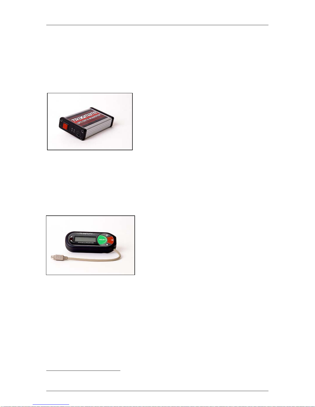
Sensor Unit
In addition to the GPS receiver to measure position and
the accelerometers to measure forces, the Sensor Unit
has digital, analog, and frequency inputs for measuring
individual aspects of vehicle performance such as RPM
or steering wheel position. These are recorded alongside
the position and force data for easy graphing.2
Four LEDs indicate power, data collection mode, GPS
signal, and data communications activity. The single
button is used for ON/OFF and for entering and exiting
data communications mode. The Sensor Unit can be used standalone or in conjunction with a
Display Unit, in which case it is entirely remotely controlled.
The Sensor Unit can be customized using the Traqview Analysis Program. You can enter Drivers,
Tracks, and Vehicles and all data is date and time-stamped so there is never any confusion. In
addition, Traqview lets you customize the unit with your name and contact information in case it is
lost or stolen.
Display Unit
The Display Unit (DU) is a major leap in low-cost data
acquisition providing in-car lap timing without a need for
external beacons. The graphical and menu-driven user
interface makes data collection easy and fun. Even more
innovative, the DU is a USB-powered data storage
device. Unclip it from your car and plug it into your PC’s
USB port. The Display Unit powers up and transfers
your data right into Traqview where your sessions are
listed by Driver, Track, and Vehicle.
The DU has a backlit bitmapped screen for easy reading
day or night. The membrane switch has large buttons so it can be accessed with gloves and is
resistant to moisture, dirt, and grease. Mount it anywhere with Velcro or the accessory quick clip.
With the Traqmate DU, in-car lap timing has never been easier. For each track, press the
SELECT button at the start/finish line to permanently store that information in the DU. The unit
will remember that track in the future. Place the unit in Lapping Mode and watch your laps click
off. The display shows Lap Number, Lap Time, Best Lap, and whether the lap was faster or
slower that the previous lap. Lap Timing continues even if GPS signal is lost or spotty. Review
laps for any session and delete the ones you don’t want.
The Display Unit is attractive enough to use every day. When traveling to the track, turn on the
DU and you will get a nice GPS compass, atomic clock, and a speedometer.
2Available in next software release.
Traqmate User Manual V1.02 June 14, 2005
Copyright © 2005 Track Systems Technologies, LLC Page 7
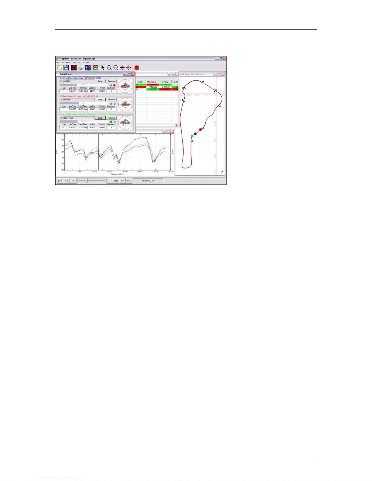
Traqview
A data acquisition system is
only as good as the analysis
program. Traqview is a new
approach that merges hard-
core data analysis with the fun
of a video game. The track
mapping is accurate and gives
an instant read on what is
happening where. Multi-car
playback lets you see
graphically who is faster where.
Record several cars in a race
and replay the entire race in
real-time, slow-mo, or fast
forward. See their speed, G
loads, braking and acceleration
for every car on the virtual
dashboard.
Traqview has all the tools you need to optimize the performance of both car and driver. For
example, you can display graphs like Velocity vs. Distance to see who is faster in which corners
and then define a sector on the map and zoom in to see braking points, instantaneous velocities,
acceleration points, and transfer speeds through a corner.
Traqview is your single point of contact for everything in the Traqmate System. Use it to upload
data from Traqmate, analyze the data, configure Tracks, Drivers, Vehicles and optional Sensors,
change the Sampling Rate, and even download future software and feature upgrades into your
Traqmate.

Traqmate User Manual V1.02 June 14, 2005
Copyright © 2005 Track Systems Technologies, LLC Page 8
Traqmate System Packages
This diagram will help you identify the
Traqmate Components. Traqmate
comes as two bundled packages.
Each includes everything you need to
collect and analyze your data.
Traqmate Basic
The Traqmate Basic package consists
of a Sensor Unit (SU), GPS antenna,
serial cable, cigarette lighter power
adapter, carrying box, and compact
data disc containing the Traqview
Analysis software and manual.
Traqmate Complete
The Traqmate Complete package
consists of a Sensor Unit (SU), a
Display Unit (DU), GPS antenna, USB
cable, SU-DU DIN connection cable,
cigarette lighter power adapter,
carrying box, and compact data disc
containing the Traqview Analysis
Software and User Manual.
Figure 1 - Traqmate System Components
Accessories
Accessories include a TraqPaq battery pack, permanent vehicle power harness, DU mounting
bracket, TraqAC SU AC adapter, extra antennas for convenient vehicle swapping, and SU
mounting tray.
TraqPaq
Battery
Pack
SU Mounting Tray DU Mounting
Bracket TraqAC Power
Supply Permanent
Power Cable

Traqmate User Manual V1.02 June 14, 2005
Copyright © 2005 Track Systems Technologies, LLC Page 9
Traqview Software Installation
NOTE: It is important to install the software and USB driver before plugging the unit into your PC.
Traqview is designed to work with most current Microsoft Windows compatible computers. Check
the Systems Requirements section of this manual to ensure that your system is compatible.
To install the software, insert the compact disc into your PC’s compact disc drive. If you do not
have a CD reader on your PC, you can download the software and user manual from the
Traqmate website at traqmate.com. You may also check there for software updates.
The CD should automatically run when inserted. If it does not, open “My Computer” and right-click
on the CD drive. Choose “Explore”. Now double-click TraqSetup.exe to run the installer program.
Traqview Analysis Software
The Traqview Installer program is self-explanatory. The default options work well for most
systems. The program is placed in the “Program Files/Track Systems folder”.
If you have a Display Unit you should install “USB Pre-Installer”. You may de-select this option if
you are installing a Traqview Basic system.
When finished, you should get an indication that the new hardware was installed automatically.
You should not have to repeat this installation in the future.
USB Driver
Once the USB drivers are installed, get your Display Unit and the mini-USB cable. Plug the cable
into the DU and into a USB port on your computer. The Display Unit should power up and your
computer will announce “Found New Hardware”.
The New Hardware Wizard will execute for the Traqmate USB Composite Device.
Choose to search ‘This Time Only’ and ‘Install Automatically’.
When given a warning, choose to ‘Continue Anyway’.
The New Hardware Wizard will execute for the Track Systems Traqmate.
Choose to search ‘This Time Only’ and ‘Install Automatically’.
When given a warning, choose to ‘Continue Anyway’.
Depending on what drivers and libraries were installed, you may be asked to restart your
computer. You will not have to install this driver again in the future.
Note: If at any time during the install the installer cannot location the USB drivers, you
may manually enter:
C:\Program Files\Track Systems\Traqmate\USB

Traqmate User Manual V1.0 June 14, 2005
Copyright © 2005 Track Systems Technologies, LLC Page 10
Traqmate Installation
These diagrams show the overall connections for the Traqmate Basic and Traqmate Complete
Systems.
Figure 2 - Traqmate Basic Connections
Figure 3 - Traqmate Complete
Connections
Sensor Unit Installation
The Traqmate sensor unit may be mounted using a variety of methods depending on the
following factors: 1) How permanent is the desired
mount, 2) where is the preferred mounting point, 3) will
the SU be connected to a Display Unit (DU).
The Sensor Unit must be mounted as flat as
possible in the vehicle and such that the arrow on
the top label points in the direction of travel.
CHOOSE A LOCATION WHERE THE UNIT WILL
NOT BE SUBJECTED TO WATER. EXCESSIVE
MOISTURE EXPOSURE WILL DAMAGE THE UNIT.
This is to ensure the accelerometers are the most
accurate and have the best range for making measurements. It is also a
good idea to place the unit as close to the vehicle’s center of gravity as
possible. While not required, especially with connection to the DU, it may
be desirable to mount the SU in a location that allows the indicator lights
to be viewed easily by the driver. Given these considerations, a position
on the floor of the front passenger footwell may work well.
The mounting of the SU may be accomplished in a variety of ways, but
the most desirable and secure method is to use the Sensor Unit

Traqmate User Manual V1.0 June 14, 2005
Copyright © 2005 Track Systems Technologies, LLC Page 11
Mounting Tray (shown here), offered as a separate accessory from Track Systems. The mounting
tray can be attached permanently to the vehicle, and by placing Velcro on the SU enclosure, and
the mounting tray, the SU is securely fastened, while at the same time being easily removable.
Once the mounting tray is aligned in the vehicle, the SU can be easily placed in the mounting tray
and the alignment is set.
Another method for mounting the SU is to apply Velcro directly to the SU and the mating piece
directly to the vehicle. This care should be taken when placing the SU on the Velcro that it is
properly aligned in the vehicle and that the SU is securely attached.
Sensor and Display Unit Operation
If the SU is going to be connected to a DU, the mounting of the SU is not as critical with respect
to gathering and downloading data. In this configuration, the DU stores the data and is the focal
point for downloading to a PC.
Sensor Unit only Operation
If the SU is going to be used in a configuration without the DU, it is desirable to have access to
the SU for downloading the data once it has been stored. Similarly, if a laptop is going to be used
to download the stored data without removing the SU, the unit should be placed in a convenient
and accessible location. In the case where the SU will be removed to download the data, the
mounting should take into account replacing the SU in a secure and aligned manner.
GPS Antenna Placement
The supplied GPS antenna has a magnetic mount,
which allows a variety of mounting options to the metal
chassis of the vehicle. In the case where the desired
location is not metal, double stick tape is a viable option
for mounting the antenna. The placement of the antenna
can have a great effect on the performance of the data
collection system. Ideally, the antenna should be placed
on the highest part of the exterior of the vehicle. Placing
the antenna inside the vehicle can cause “blind spots”
where the antenna is not able to see as many of the
GPS satellites that may be available to it. The system
works best when the antenna has the least restricted view of the sky. Once a location has been
determined for the antenna placement, the wire connecting the antenna and the SU should be
routed in a manner such that it is not placed under stress, and the wire will not be exposed to
frequent bending or crimping. After routing the wire to the SU, connect the antenna to the SU by
screwing the antenna wire to the GPS connector indicated on the end panel of the SU.
Connecting a Sensor Unit to a Display Unit
In the configuration where the Sensor Unit and the
Display Unit will both be used, a 15’ DIN-to-DIN
connection cable is provided. This is a standard male-to-
male cable, which allows a great deal of flexibility in the
placement of the SU and DU. The length of the cable is
typically sufficient such that it can be routed as to be
securely protected from damage during normal vehicle
operation. In the case where the distance between the
SU and DU does not require a 15’ cable, a shorter
version can be purchased at most computer or
electronic supply stores.

Traqmate User Manual V1.0 June 14, 2005
Copyright © 2005 Track Systems Technologies, LLC Page 12
Power Connection
In all installations, the SU must be supplied with a power source at all times it is in operation. For
Traqmate Complete, the DU can receive power via the DIN extension cable from the SU or via
the USB cable when connected to a PC for uploading sessions.
The SU was designed to be powered from a +12 VDC battery supply in four different ways; a
permanent wiring harness in the vehicle, a cigarette lighter adapter, a battery pack, and a wall
charger. Each of these will be discussed
separately.
Cigarette Lighter Adapter
For installations where a permanent power supply
connection is not required or desired, the cigarette
lighter adapter offers a quick and convenient solution. This adapter can be secured to the SU by
inserting the plug into the power connector (PWR) on the SU and tightening the threaded nut to
the power (PWR) socket. Once the SU and the power connector have been secured, the
cigarette lighter adapter can be plugged into one of the cigarette lighter sockets located in the
vehicle. It should be noted that many automobiles have cigarette lighter sockets that are always
ON and do not turn the power off when the ignition switch has been turned to the OFF position.
The cigarette lighter adapter has a RED LED to indicate that vehicle battery power is presented to
the adapter. During extended vehicle idle periods, the cigarette lighter adapter should be
removed from the vehicle socket to prevent vehicle battery drain.
TraqPaq Battery Pack
The TraqPaq can be utilized to power the SU during periods in
which the SU is disconnected from the vehicle power and
operation is still required, or in vehicles in which no installation has
been performed. It is ideal for moving the SU from vehicle to
vehicle. The TraqPaq Battery Pack is capable of supporting the SU
power requirements for 3-5 hours using Alkaline batteries. DO
NOT USE RECHARGEABLE NiCad BATTERIES since they do
not provide enough voltage. This is generally enough time to run several track sessions, or all day
if the unit is powered off between sessions. The SU can be powered by the TraqPaq during
periods in which the SU data is being downloaded to a computer containing the Traqview
software.
The TraqPaq is attached to the SU by inserting the power plug into the power connector socket
(PWR) on the SU. The TraqPaq power plug contains a threaded nut for securing the plug to the
power jack (PWR) on the SU. The TraqPaq accommodates four (4) AA batteries that result in a 6
volt power source. Depleted batteries can be replaced by removing the screw and sliding the
cover off. Care should be exercised when replacing the batteries, as to observe the polarity for
each cell. Once the batteries have been properly installed, the cover should be replaced and
secured by inserting and tightening the cover screw.
Permanent Wiring Harness Installation
The power cable is an 18 feet, two conductor, red and black
zip cable that has a plug on one end and is not terminated on
the other end. The power plug contains a threaded nut for
securing the plug to the power jack (PWR) on the Traqmate
Sensor Unit (SU). The other end of the cable is intended to
connect to either the automobile battery or a junction box.
Since the SU mounting location can vary widely (trunk, under
seat, floorboard, etc.) the required cable length will also vary.
Consequently, the cable can be cut to an appropriate length suitable for your automobile, once
the mounting location is selected.

Traqmate User Manual V1.0 June 14, 2005
Copyright © 2005 Track Systems Technologies, LLC Page 13
18' cable - cut to length
Vehicle GND
Crimp Splice
Vehicle +12V
3A 2AG Fuse
Power
Connector
Figure 4 - Permanent Wiring Harness
The red wire is to be connected to the positive (+) side of the battery and the black lead to the
negative (-) or chassis side. A fuse holder has also been included with the power cable. One end
of the fuse holder contains a connector butt-splice and the other end is stripped for the application
of a crimp lug or other suitable connector (not included). Once the power cable length has been
determined, the excess length can be cut off. The red conductor of the zip power cable should be
stripped about 3/8 inches and inserted / crimped into the crimp butt-splice. The bare end of the
fuse holder should be inserted / crimped into a crimp lug or other suitable connector (not
included). The lug should be connected to the positive (+) battery terminal or a switched positive
(+) terminal.
It should be mentioned that when the SU is connected directly to the positive (+) battery terminal,
the SU will continue to be powered when the ignition switch has been turned to the OFF position.
Extended vehicle idle periods may drain the vehicle battery if the unit is not turned off using the
front panel button. If this is a concern for your installation, efforts should be made to connect the
positive (+) terminal to a switched supply.
The black conductor should be stripped and a crimp lug or other suitable connector applied (not
included). The lug on the black conductor should then be connected to the negative (-) battery
terminal or chassis ground.
TraqAC Power Supply
The TraqAC can be utilized to power the SU during periods in which
the SU has been disconnected from the vehicle power and operation is
still required. That is, the SU can be powered by the TraqAC during
periods in which the SU data is being downloaded to a computer
containing the Traqview software.
The TraqAC is attached to the SU by inserting the power plug into the power connector socket
(PWR) on the SU. Once the TraqAC has been connected to the SU, it is ready to plug into the
110VAC wall outlet.
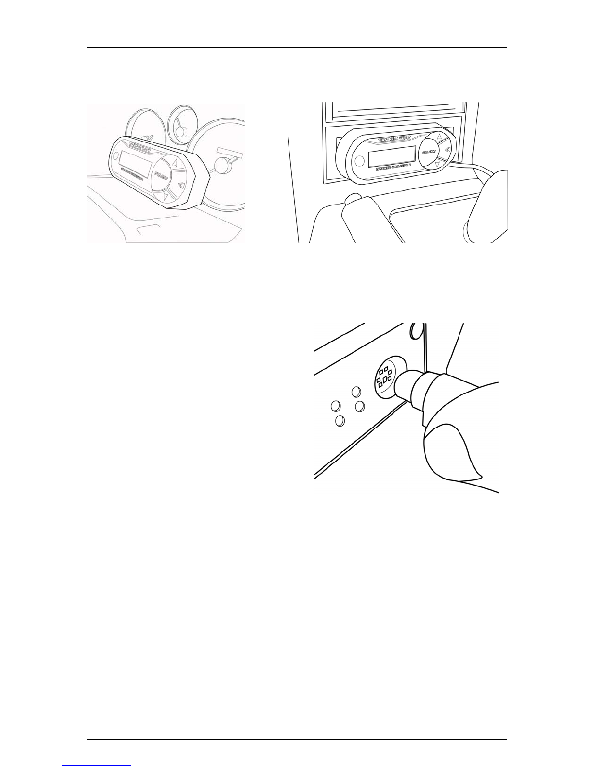
Traqmate Display Unit Installation
Mounting
It is important to mount the Display Unit in such a manner that it can be easily seen by the driver
but does not interfere with the operation of the vehicle. You may use the Velcro strips provided to
attach the unit to your gauge cluster or center console as shown below. This is a very flexible
approach to mounting the DU, and may be desirable for most applications. Care should be taken
however, such that the DU does not come loose during the anticipated operation of the vehicle.
The DU has been designed with the standard cellular-phone mounting pattern on the back cover.
This allows many of the cellular mounting options to be used in mounting the DU. These include
clamshells, goosenecks, and the Display Unit Mounting Bracket, which is sold as an accessory by
Track Systems, as the preferred mounting bracket. With the Display Unit Mounting Bracket, the
DU can quickly and easily be clipped onto the mating portion of the bracket, which remains
permanently affixed to the vehicle.
Traqmate User Manual V1.0 June 14, 2005
Copyright © 2005 Track Systems Technologies, LLC Page 14
Regardless of the mounting mechanism used to secure the DU, care should be taken to avoid
strain on the DU cable, and connecting cable, as this can put stress on the DU, the connectors,
and the cables.
Figure 5 - DU Gauge Cluster Mount
Figure 6 - DU Console Mount
Connecting to the Sensor Unit
After connecting the DU to the SU using the DIN
extension cable, the Display Unit will power up. It
will briefly display the Firmware revision number of
the SU and the DU. If instead,
* SU NOT CONNECTED *
is displayed, there is no communication between
the SU and DU and the system will not work for
data collection. You can still upload sessions and
download configuration to the DU.
Possible Remedies:
• Ensure SU has power.
• Ensure DIN Extension cable is firmly
plugged into both the DU and SU.
• Ensure SU is in operable state. Cycle power on SU.
• Ensure SU has proper firmware.
• Ensure DU has proper firmware.
If you see the message
SW Mismatch, Reload
then the firmware in the DU and SU are incompatible. Reload the firmware of both the SU and
DU with the latest downloads available on the traqmate.com website and try again.
Traqmate User Manual V1.0 June 14, 2005
Copyright © 2005 Track Systems Technologies, LLC Page 15
Traqmate Basic
System Description
Traqmate Basic is the easiest form of data acquisition. You can literally just Velcro the unit into a
car and get very sophisticated results in a matter of minutes. Data is stored in Flash memory
inside the Sensor Unit and can be extracted through the COM serial port on the front panel of the
unit.
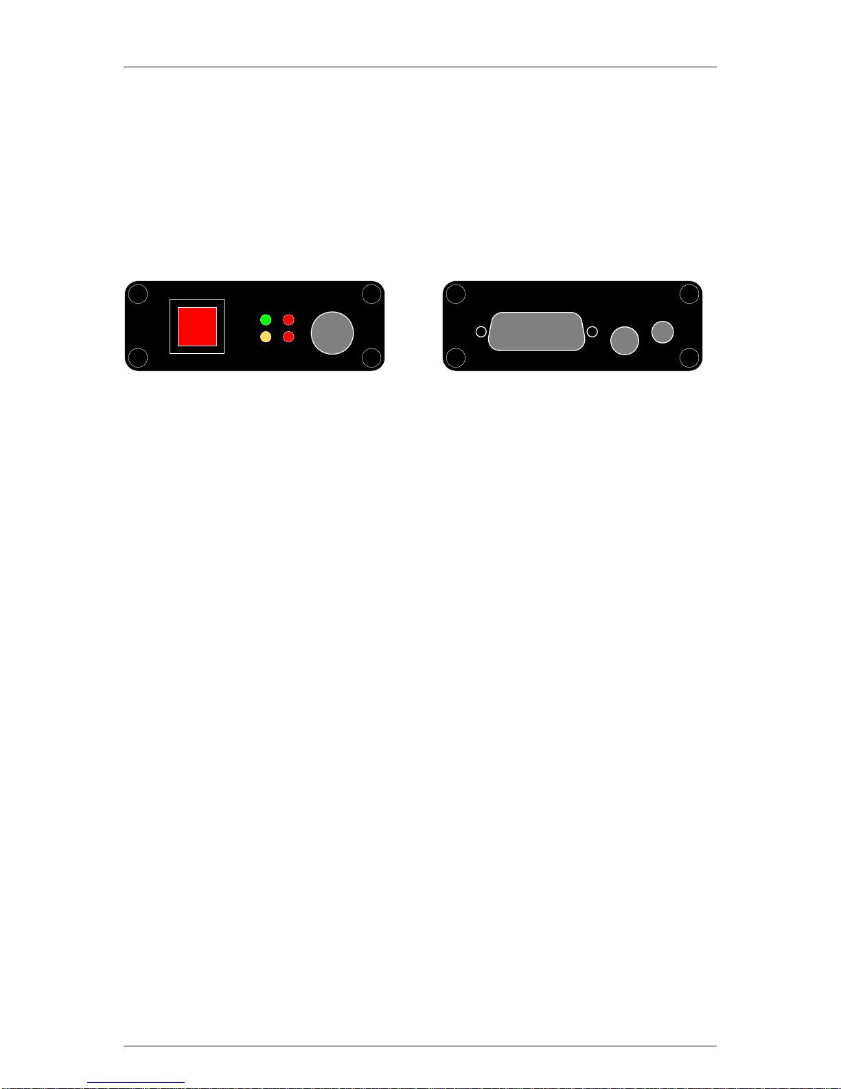
Controls
wr / recp
com
cmOgPS
wrpgPS
aUX
pwR r ce
Figure 7 - Sensor Unit Front and Rear Panel
The front panel contains a power switch button, four LED lighted indicators, and a
communications port.
PWR / REC –Power Switch Button
• Turns unit on - push button once, “PWR” LED goes on
• Turns Record on - push button while “PWR” LED is on and “REC” LED goes on; a
second push and the “REC” LED goes off
• Turns unit off - hold button down until “PWR” LED goes off
LED Light Displays
• “PWR” LED - lights green when power is on
• “REC” LED - lights red when Record is turned on
• “COM” LED - lights yellow when Communications is in progress on the COM port
• “GPS” LED - flashes red to indicate that you have obtained GPS coverage. The rate of
flashing indicates the sampling rate currently selected.
COM – Communications Port
• Plug the Traqmate Display Unit (DU) into the Sensor Unit
• Plug in a PC communications cable to download into Traqview
The back panel contains an auxiliary port, a GPS port, and a power port.
PWR – Power Port
• Plug in the cigarette lighter power adapter
• Plug in the power cable from the car battery power
• Plug in the battery pack power cable
• Plug in the AC adapter power cable
GPS – GPS Antenna Port
• Plug in the GPS antenna
AUX – Auxiliary Port
• Auxiliary connector port for digital and analog sensors (This feature will be available in
future releases.)
Traqmate User Manual V1.0 June 14, 2005
Copyright © 2005 Track Systems Technologies, LLC Page 16
Traqmate Complete
System Description
Traqmate Complete builds on the Traqmate Basic simplicity to add immediate feedback to the
driver in the form of lap times on a Display Unit (DU). It also provides more visibility and control of
the collected data and useful tools for vehicle performance tuning. Data is stored inside the
Display Unit and can be extracted using the mini-USB port on the end of the unit.
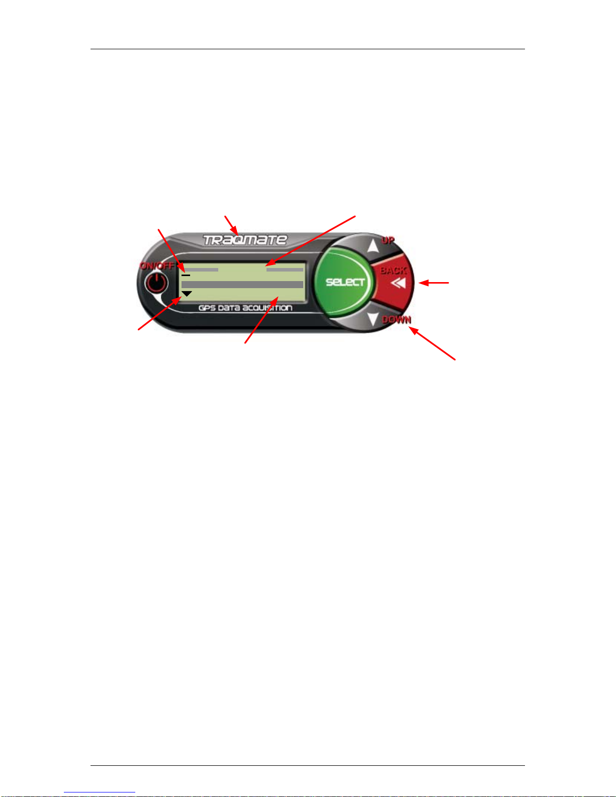
Controls
Mini USB
Port
Connection to
Sensor Unit
Main Menu Record Data
View Sessions
Setup
Menu
Title
Indicates Top
of Menu List
Indicates More
Choices Below
Screen Menu Choices
Backlight
Figure 8 - Display Unit Controls
The DU contains six buttons, a graphical LCD screen, a DIN cable to connect to the Sensor Unit,
and a mini-USB port for connection to a computer.
ON/OFF – Power Switch Button
• Turns unit on - push button once, startup screen appears and “PWR” LED goes on in the
Sensor Unit
• Turns unit off - hold button down until signoff screen appears on LCD display and “PWR”
LED goes off in the Sensor Unit
Traqmate Logo – Backlight Button
• Turns LCD backlight on/off – toggles LCD backlight on/off
Select Button – Executes Menu Functions
• Selects highlighted items on the LCD display screen
Back Button – Exits Menu Functions
• Goes up one level in menus
• Exits a mode such as lap timing and returns to menu
Up Button
• Press to go up one item in a list
Down Button
• Press to go down one item in a list

Traqmate User Manual V1.0 June 14, 2005
Copyright © 2005 Track Systems Technologies, LLC Page 17
Menu System
All of the Display Unit features are accessible through a text menu system. To access a feature
use the UP and DOWN buttons to highlight the item you want on the screen. Press SELECT to
activate that item. Some items actually perform a function while others go to other menus. This
chart shows the menu tree.
Main Menu
Record Data
Laps – enters lap timing mode
Choose Start / Finish – Unit is waiting for driver to choose a Start / Finish location
Searching for Start / Finish – Unit is waiting for vehicle to cross Start / Finish Line
Erase Start / Finish – erases Start / Finish for chosen track
Drive – enters data recording mode with directional indicators
Autocross – enters hi-res recording mode
1/4 Mile – enters hi-res recording mode
1/8 Mile – enters hi-res recording mode
View Sessions
List of Recorded Sessions
View Laps
Steps through recorded lap times
Erase Data
Erases selected session
Session Detail
Displays driver, car, track, session memory usage, start date/time, end
date/time, laps recorded, sampling rate, and temperature at start.
Setup
Driver
Pick from list of drivers entered in Traqview
Vehicle
Pick from list of vehicles entered in Traqview
Track
Pick from list of tracks entered in Traqview
Sampling Rate
10 Hz
Selects 10 samples per second
20 Hz
Selects 20 samples per second
40 Hz
Selects 40 samples per second
Contrast
UP or DOWN to change LCD contrast
Erase Sessions
Erases all sessions but retains drivers, vehicles, tracks
Other Features
GPS Compass
Enters non-recording GPS compass mode. Shows time, speed, and heading.
GPS Information
Enters non-recording GPS information mode. Shows x, y G-forces, date and time,
GPS location in latitude/longitude, heading, speed, and temperature.

Traqmate User Manual V1.0 June 14, 2005
Copyright © 2005 Track Systems Technologies, LLC Page 18
Features
Lap Timing
The lap timing feature measures the interval of time between passes of a chosen spot (Start /
Finish Line). It uses both location and heading to determine the exact spot to 1/10th second
accuracy. You can be at any place on the track but must be heading in approximately the same
direction as the reference lap for the timing to work.
Start / Finish
Line Valid positions
for lap timing
Initial position
Bad heading
Too far away
Figure 9 - Lap Timing
The Start/Finish Location is stored on the Display Unit for each track, so once you enter it you
should not have to enter it again unless you delete the track from memory or upgrade your DU
software.
To use the lap timing feature Select “Record Data” from the Main Menu and then Select “Laps”.
You will see
Figure 10 - Acquiring GPS Screen
until GPS signal is acquired. If this takes more than a minute, check your antenna connection and
ensure that the antenna has a clear view of the sky.
Traqmate User Manual V1.0 June 14, 2005
Copyright © 2005 Track Systems Technologies, LLC Page 19
Once Traqmate has GPS signal, it will check to see if there is a Start/Finish position stored for the
current track. If not, you will see
Figure 11 - Recording a Start / Finish Location
Proceed around the track until you reach the Start/Finish line. Make sure you cross the line the
same way that you will when driving at full speed. As you reach the line press the SELECT button
to record the Start / Finish line and save it in permanent memory. At this time the Timing Screen
will appear.
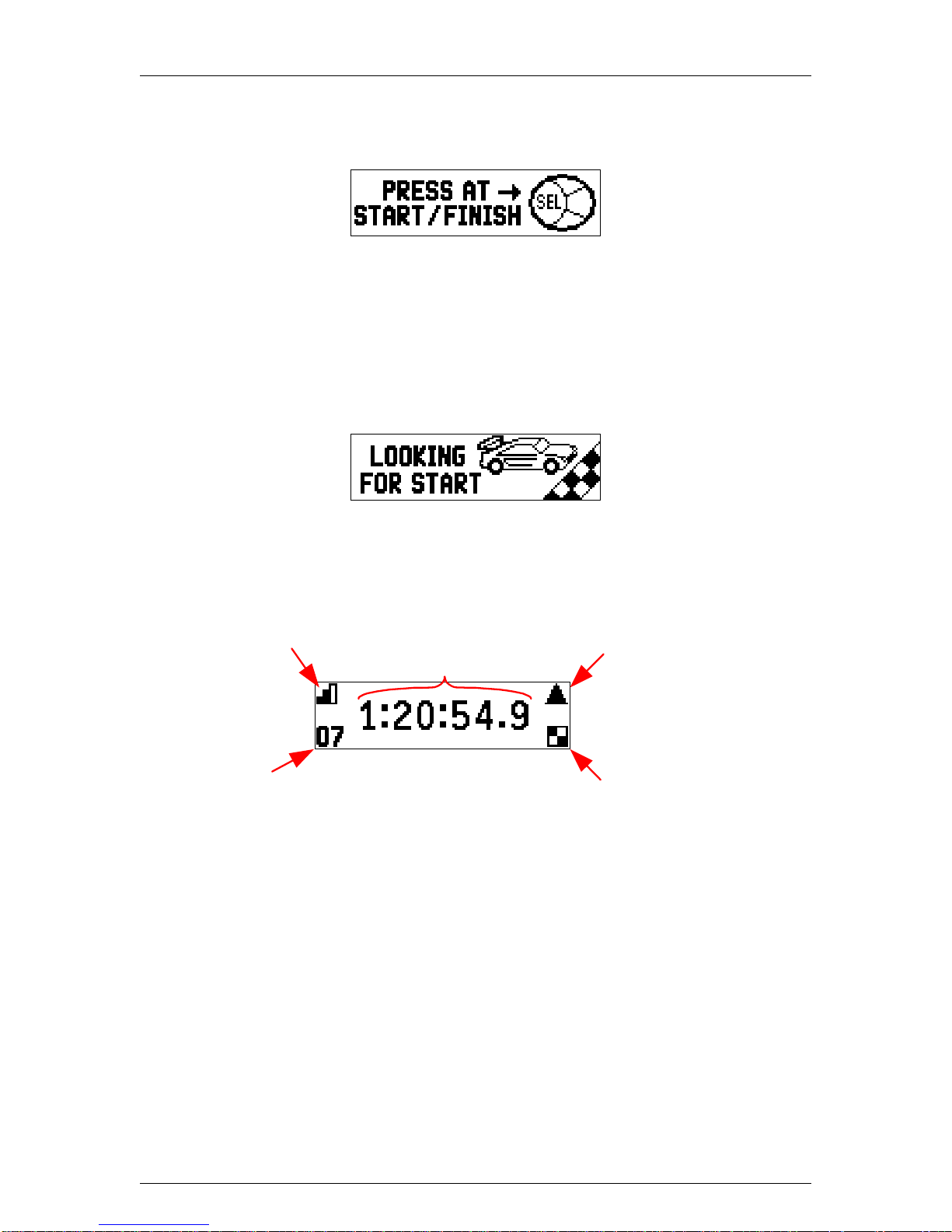
If you have already recorded a Start / Finish location for the chosen track, the following screen
will appear.
Figure 12 - Searching for Start / Finish Line
This will stay onscreen until you cross the Start / Finish line when the Timing Screen will appear.
Indicates lap time of
1 hour, 20 minutes,
54.9 seconds
Up arrow when lap is
better than previous,
Down arrow when worse
Flag indicates
best lap
GPS signal
strength indicator
Lap counter
Figure 13 - Lap Timer Screen
The numbers will start over whenever the Start / Finish line is crossed and the lap counter will
increment. The lap time from the previous lap will be held onscreen for 1 minute to allow time for
viewing, and then the counting will resume.
Traqmate User Manual V1.0 June 14, 2005
Copyright © 2005 Track Systems Technologies, LLC Page 20
Traqview Analysis and Configuration Program
Traqview is the source for configuring, updating, and analyzing data from your Traqmate. After
installation, you can launch the program from the Windows Start Menu, a desktop icon, or from a
toolbar icon.
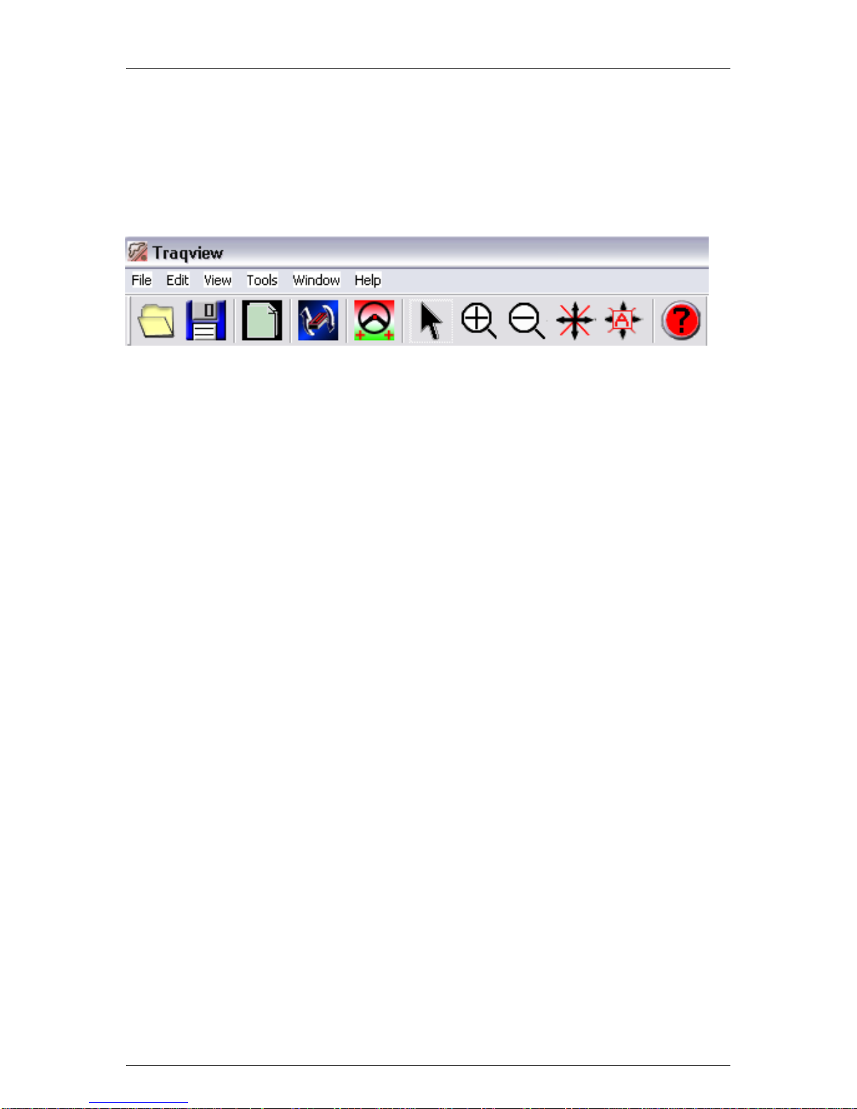
Toolbar Buttons and Controls
Open Save Copy Upload Add
Driver Pointer ZoomIn ZoomOut Pan AutoPan Help
Figure 14 - Menu Bar Buttons
Menu Options
File
Open – opens a session file (.tqm) or an analysis file (.tqs)
Close – closes current file
Save – saves current analysis as a .tqs file
Save As – saves current analysis to a name chose by user
Add Driver – opens a session file and adds driver to dashboard
Export – saves current graph as an image for later printing or incorporation into a document
Exit – exits Traqview program
Edit
Copy – copies currently highlighted window to Windows clipboard
View
Toolbar – toggles toolbar on/off
Auto Pan – a mode that causes a selected driver to always stay within the track map and graph
windows
Driver List – choose driver for window to follow on track
Pointer – selects the pointer tool (for moving Start/Finish Line and Manipulating Segments)
Zoom – selects the Zoom In tool (for magnifying track or graphs) When Zoom tool is selected,
shift key will invert the zoom direction.
Pan – selects the Pan tool for dragging track and graphs around in the window
Refresh – resets graphs and map back to starting point, redraws screens
Tools
Session Upload – connects to Traqmate to upload session information
User Setup – connects to Traqmate to setup user information
Unit Information – connects to Traqmate to change user information
Firmware Update – connects to Traqmate to update SU or DU firmware
Options – controls Traqview local options
Window
Close All – closes all windows
Window List – choose a window to display on top
Help
About Traqview – displays Traqview version information
Other manuals for Traqmate
1
Table of contents
Popular Automobile Accessories manuals by other brands

Daken
Daken Saturn Evo Mounting instructions

Cruz
Cruz Evo Rack E28-158 Assembly instructions

Warn
Warn 90865 installation guide

Veigel
Veigel BHA00005 installation manual

Car Solutions
Car Solutions MB10 Series installation guide

Directed Electronics
Directed Electronics Xpresskit Solex PLJX installation guide

MASCOT
MASCOT SMARTCHARGER user manual

Lectron
Lectron Level 1 user manual

CM3-Computer
CM3-Computer Car Key Ring HD Spy Camera operating instructions

Davis Instruments
Davis Instruments DriveRight 600E Installation and user's guide... installation guide

Atera
Atera SIGNO 045 052 User information

Malone
Malone Cargo Series Installation & Loading Instructions


