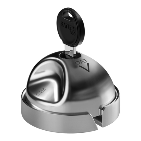
Daken Saturn Evo User manual

MONTAGE HANLEIDING
ISTRUZIONI DI MONTAGGIO
MOUNTING INSTRUCTIONS
NOTICES DE MONTAGE
INSTRUCCIONES DE MONTAJE
MONTAGEANLEITUNG
ИНСТРУКЦИЯ ПО СБОРКЕ

INDICE
INDEX
4
6
9
9
9
Kit installazione
Montaggio
Principio di funzionamento
Manutenzione
Raccomandazioni
ITA
4
14
17
17
17
Kit d’installation
Montage
Principe de fonctionnement
Entretien
Recommandations
FRA
4
22
25
25
25
Lieferumfang
Montage
Funktionsweise des produkts
Wartung
Anweisungen
DEU
4
10
13
13
13
Mounting kit
Mounting
How it works
Maintenance
Advices
ENG
4
30
33
33
33
Montage set
Montage
Hoe werkt het
Onderhoud
Adviezen
NL
4
18
21
21
21
Kit de instalación
Montaje
Principio de funcionamiento
Manutención
Recomendaciones
ESP
4
26
29
29
29
Комплект для установки
Монтаж
Принцип работы
Техническое обслуживание
Рекомендации
RUS
Guarda il video di montaggio
Watch the mounting instructions video
Regardez la vidéo de montage
Vea aquí el video de instrucciones
Schauen Sie das Anleitungsvideo an
Смотреть инструкцию видео
Bekijk de montage video
Scrivi qui il tuo key code
Write your key code here
Merci de noter ci-dessous le code de la clé
Schreiben Sie hier Ihren Schlüsselcode
Escriba aquí su key code
напишите свой код ключа здесь
Schrijf hier uw sleutelcode
IT
Presentare il Key Code al proprio
Rivenditore per richiedere il
DUPLICATO DELLA CHIAVE.
EN
Show the Key Code to your usual
dealer to get a KEY DUPLICATE.
FR
Présentez le code de la clé à votre
revendeur pour demander un
DOUBLE DE CLÉ.
ES
Enseñar el Key Code a su propio
revendedor para solicitar el
DUPLICADO DE LA LLAVE.
DE
Zeigen Sie Ihrem Händler
den Schlüsselcode, um einen
ERSATZSCHLÜSSEL anzufordern.
RU
Для получения ДУБЛИКАТА
КЛЮЧА предоставьте Код Ключа
уполномоченному реселлеру.
NL
Laat de sleutelcode zien bij je Saturn
dealer voor extra reserve sleutels.
KEY CODE

ES
Plantilla adhesiva por los agujeros
2 Llaves
Armazón en acero inoxidable
AISI 304 satinado
2 Placas en acero inoxidable
AISI 304 satinado
2 Espesores en plástico rígido
2 Protecciones de goma suave
Kit de tornillos
1
1
2
2
3
3
4
4
5
5
6
6
IT
Dima adesiva per fori
2 Chiavi
Scocca in acciaio inox
AISI 304 satinato
2 Flange in acciaio inox
AISI 304 satinato
2 Spessori in plastica rigida
2 Protezioni in gomma morbida
Kit viteria
1
2
3
4
5
6
7
EN
Drill template
2 Keys
External shell in AISI 304
brushed stainless steel
Half-flanges in AISI 304
brushed stainless steel
2 Plastic shims
2 Rubber protections for the van body
Fixing kit
1
2
3
4
5
6
7
FR
Gabarit adhésif de perçage
2 Clefs
Boule en acier inox AISI 304 satiné
2 Supports de xation en acier inox
AISI 304 satiné
2 Cales de niveau en plastique
2 Cales de protection en mousse
Kit visserie
1
2
3
4
5
6
7
DE
Bohrschablone
2 Schlüssel
Gehäuse aus gebürstetem
Edelstahl AISI 304
2 Flansche AISI 304
2 Hartkunststoffeinlagena
2 Weichgummieinlagen
Schraubensatz
1
2
3
4
5
6
7
NL
Boor template
2 Sleutels
Slot, buiten schaal in Aisa geborsteld
304rvs
2 Halve flensen geborsteld Aisa304
rvs
2 Plastic shims
2 Rubber bescherming voor de
carrosserie
Montage set
1
2
3
4
5
6
7
7
RU
Клейкий шаблон для отверстий
2 Ключа
Корпус из сатинированной
нержавеющей стали aisi 304
2 Фланца из сатинированной
нержавеющей стали AISI 304
2 Вкладыша из жесткого пластика
2 Предохранителя из мягкой
резины
Набор винтов
1
2
3
4
5
6
7
7
KIT INSTALLAZIONE • MOUNTING KIT • KIT D’INSTALLATION KIT DE INSTALACIÓN • LIEFERUMFANG • УСТАНОВОЧНЫЙ НАБОР • MONTAGE SET

ITA ITA
6 7
MONTAGGIO
FASE 1: AVVERTENZE E POSIZIONAMENTO
Dal sito www.daken.it puoi visualizzare le indicazioni di montaggio
personalizzate in base al modello di furgone.
ATTENZIONE
Prestare particolare attenzione a non montare il dispositivo sulla parte
laterale anteriore tra lo sportello passeggero e la porta scorrevole.
Prima di procedere al montaggio accertarsi che le portiere siano perfettamente
allineate. In caso di disallineamento, se possibile, effettuare la registrazione delle
portiere.
Evitare zone con particolari piegature della lamiera esterna.
Se necessario, servirsi degli spessori in plastica rigidi inseriti nel kit per rendere
piane le superci.
Prima di forare, vericare che non ci siano interferenze o altri elementi interni.
Può essere montato sul portellone posteriore e/o su quello laterale del veicolo.
A pag. 30 trovi tutte le immagini di supporto per ogni fase di montaggio, da a .
MONTAGGIO
FASE 2: FORATURA
I fori vanno effettuati su porta mobile aperta per non danneggiare la guarnizione.
Si consiglia di forare inizialmente con punta di diametro inferiore e
successivamente con punta secondo diametro scelto.
I due montaggi non sono tra loro incompatibili:
in base alle proprie esigenze e/o preferenze, è possibile utilizzare ove necessario
in parte viti corte (con fori Ø6) e in parte viti lunghe (con fori Ø4.5).
Sono previste più opzioni di foratura in base alle diverse esigenze: utilizzare
la dima per individuare, tra i punti di foratura a disposizione, quelli più idonei al
proprio veicolo. Segnare i punti di foratura e rimuovere la dima.
Una volta realizzati i fori, pulire la supercie del portellone, eliminando anche
eventuali bave di lavorazione e trattare la supercie forata con vernice antiruggine.
Effettuare 1 foro ø3.5 sulla sola porta battente/scorrevole.
A
A G
B
Eseguire i fori in base alla viteria più adatta al montaggio sul proprio veicolo:
A. Montaggio con viti lunghe, rondelle e dadi: fori ø4.5
B. Montaggio con viti corte ed inserti lettati per lamiere sottili, max 2.5 mm: fori ø6.
C
In caso di utilizzo di viti corte, procedere con il montaggio degli inserti lettati
con pinza specica.
D

ITA ITA
8 9
MONTAGGIO PRINCIPIO DI FUNZIONAMENTO
MANUTENZIONE
RACCOMANDAZIONI
FASE 4: MONTAGGIO SCOCCA
Se necessario servirsi degli spessori in plastica per allineare le flange.
ATTENZIONE Non rimuovere il Sigillo di Garanzia dietro la scocca.
Se rimosso, il prodotto non è più protetto da garanzia.
Sfruttando i fori ad asola, regolare il posizionamento della flangia smussata.
Completare il montaggio con viti M4 lunghe o corte, secondo il montaggio
precedentemente scelto.
Tagliare la parte eccedente delle viti per non danneggiare la guarnizione del
veicolo.
Vericare il corretto funzionamento del prodotto completo.
APERTURA
CHIUSURA
Inserire la chiave e ruotarla in senso orario di 180°; ruotare la scocca nel verso
opposto. Ruotare la chiave di 180° in senso antiorario ed estrarla. Il dispositivo
NON è in sicurezza.
Lubricare con prodotto specico il cilindretto ogni 2500 cicli circa e in ogni
caso ogni 4 mesi. Si consiglia un grasso lubricante siliconato spray.
La messa in sicurezza delle porte è ad esclusiva discrezione dell’utilizzatore;
Durante le comuni operazioni di lavaggio del veicolo evitare getti d’acqua
direttamente sul dispositivo.
Far eseguire il montaggio da personale specializzato;
Vericare periodicamente il corretto funzionamento del prodotto.
Non forzare l’apertura con la chiave esercitando una forza eccessiva;
Utilizzare solamente la chiave inserita nel kit per aprire e chiudere il sistema;
Utilizzare solo i componenti originali forniti di serie;
Insieme alla chiusura della serratura, è sempre consigliata la chiusura
centralizzata del mezzo.
Inserire la chiave e ruotarla in senso orario di 180°; ruotare la scocca nello
stesso verso no a quando i simboli del lucchetto siano visibili in asse verticale.
Ruotare la chiave di 180° in senso antiorario ed estrarla. Il dispositivo è in
sicurezza.
Aprire la porta mobile e applicare la scocca sulla flangia.
Ruotare la scocca di 180° .
F
Dall’interno della porta mobile, ssare la scocca alla lamiera con vite di ne
corsa M3,5x14 .
G
FASE 3: MONTAGGIO FLANGE
Posizionare le due protezioni in gomma morbida e le due flange in
corrispondenza dei fori secondo il seguente criterio :
• Flangia dritta: su porta mobile
• Flangia smussata: su porta o lamiera ssa
E

10 11
ENGENG
MOUNTING
STEP 1: WARNINGS AND POSITIONING
Visit www.daken.it for the specic mounting instructions for your van.
CAUTION
Do not install the device on the forepart of the side door between the
passenger door and the sliding door.
Before installing the device, check that the doors are perfectly aligned.
If the doors are not aligned, calibrate the doors.
Prefer smooth surfaces to areas where the van body is irregular or double.
If necessary, use the rubber protections to level and/or align the surfaces.
Before drilling, check that there is no obstacle or component inside.
The device can be installed both on the rear and on the side door of the van.
On page 30-35, you can nd images showing the installation phases - .
MOUNTING
STEP 2: DRILLING
To avoid damaging the seal, drill the holes with the movable door open.
We recommend to begin with a drill bit with a smaller diameter and then
proceed with a drill bit of the chosen diameter.
A and B are compatible with each other:
according to your needs and/or preference, if necessary you can use both short
screws (holes ø6) and long screws (holes ø4.5).
There are several drilling options to meet all the different needs: using the
drill template, choose the more suitable drilling points for your van among those
available. Mark the drilling points and remove the template.
After drilling, clean the door surface and remove any burr. Better treat the door
surface with rust preventive paint.
Drill 1 hole ø3.5 on the movable/sliding door.
A
A G
B
Drill according to the most suitable xing kit for your van:
A. Installation with long screws, washers and nuts: holes ø4.5.
B. Installation with short screws and threaded inserts for thin sheet, max 2.5 mm:
holes ø6.
C
If you choose short screws, install the threaded inserts with specic pliers.
D

12 13
ENGENG
MOUNTING HOW IT WORKS
MAINTENANCE
ADVICES
STEP 4: SHELL MOUNTING
If necessary, use the plastic shims to align the half-flanges.
CAUTION Do not remove the Warranty Seal behind the shell.
If removed, the product is not under guarantee anymore.
Using the oval holes, calibrate the chamfered half-flange.
Complete mounting with short or long M4 screws, according to the chosen
mounting.
Cut the exceeding part of the screws to avoid damaging the seal of the van.
Check that the device works properly.
OPENING
CLOSING
Insert the key and turn it 180° clockwise; turn the shell in the opposite direction.
Turn the key 180° anticlockwise and extract it. The device is NOT secured.
Securing is at complete discretion of the user.
Make sure mounting is performed by technicians.
Lubricate the cylinder with a specic product every 2500 cycles and at least
every six months. A silicone lubricant is recommended.
When washing the vehicle, avoid pointing the water jet directly on the device.
Periodically check that both the product and the lever work properly.
Do not pry open the device by forcing the key.
Use only the key included in the kit to open/close the device.
Use only the original components included in the kit.
It is recommended to secure both the van lock and the central locking of the
vehicle.
Insert the key and turn it 180° clockwise; turn the shell in the same direction
up to the lock symbols are on vertical axis. Turn the key 180° anticlockwise and
extract it. The device is secured.
Open the movable door and place the external shell on the half-flange,
turn the shell 180° .
F
From the inside of the movable door, x the shell with the stop screw M3.5x14 .
G
STEP 3: HALF-FLANGES MOUNTING
Place the 2 rubber protections and the two half flanges in correspondence
with the holes, as follows :
• Straight half-flange: on the movable door
• Chamfered half-flange: on the xed door or van body
E

14 15
FRAFRA
MONTAGE
PHASE 1: NOTICES ET EMPLACEMENT
Sur le site Internet WWW.DAKEN.IT vous pouvez consulter les instructions de
montage personnalisées en fonction du modèle de fourgon.
ATTENTION
Merci de ne pas installer la serrure sur le côté antérieur an de ne pas gêner
l’ouverture de la porte passager.
Avant la pose du produit, assurez-vous qu’il n’y ait aucun affleurement entre les
surfaces des portes. En cas de désalignement, si possible, veuillez d’abord régler
les portes.
Privilégiez surfaces planes sans pliages complexes sur la tôle extérieure.
Si nécessaire, utilisez les cales de niveau en plastique pour compenser un éventuel
affleurement entre les surfaces des portes.
Avant de percer, vériez qu’il n’y ait pas d’interférences ou d’autres éléments
internes.
La serrure peut être posée sur les portes arrière et latérales du véhicule.
À la page 30-35, vous trouverez les images explicatives de chaque phase
d’installation, de à .
MONTAGE
PHASE 2 : PERÇAGE
Percez avec la porte mobile ouverte pour ne pas endommager le joint.
Au départ, il est recommandé de réaliser des trous avec un foret inférieur
et puis terminez le perçage avec celui indiqué.
Les deux montages ne sont pas incompatibles : selon vos besoins et / ou
préférences, vous pouvez utiliser, si nécessaire, des vis courtes (avec trous Ø6)
et des vis longues (avec trous Ø4,5).
Plusieurs options de perçage sont prévues en fonction des différents besoins :
utilisez le gabarit pour individuer parmi les points de perçage disponibles ceux qui
conviennent le mieux à votre véhicule. Marquez les points de perçage et enlevez
le gabarit.
Après le perçage, nettoyez bien la surface de pose et éliminez les bavures.
Nous recommandons d’appliquer un traitement antirouille sur la tôle aux points de
perçage.
Réalisez 1 trou ø3.5 sur la porte mobile/coulissante.
A
A G B
Réalisez les trous en fonction des vis retenues pour le montage sur votre véhicule :
A. Montage avec vis longues, rondelles et écrous : trous ø4.5.
B. Montage avec vis courtes et inserts letés pour tôles nes, max 2.5 mm: trous ø6.
C
Si vous utilisez des vis courtes, procédez au montage des inserts letés avec
une pince.
D

16 17
FRAFRA
MONTAGE PRINCIPE DE FONCTIONNEMENT
ENTRETIEN
RECOMMANDATIONS
PHASE 4 : MONTAGE BOULE
Si nécessaire, utilisez les cales de niveau en plastique pour aligner les supports.
ATTENTION Ne retirez pas le sceau de garantie derrière la boule.
S’il est retiré, le produit n’est plus protégé par la garantie.
Utilisez les trous oblongs pour régler l’emplacement du support biseauté.
Terminez le montage avec des vis M4 longues ou courtes, en fonction du
montage précédemment choisi.
Coupez l’excès de vis pour ne pas endommager le joint du véhicule.
Vériez le bon fonctionnement du produit.
OUVERTURE
FERMETURE
Insérez et tournez la clé de 180° dans le sens des aiguilles d’une montre ;
tournez la boule dans l’autre sens. Tournez la clé de 180° dans le sens inverse des
aiguilles d’une montre et retirez-la. Le dispositif N’EST PAS sécurisé.
Lubriez le cylindre avec un produit spécique tous les 2500 cycles et en tout
cas tous les 4 mois. Nous recommandons une graisse lubriante à la silicone.
La sécurisation des portes ne dépend que de la volonté de l’utilisateur ;
Pendant les lavages du véhicule, évitez d’adresser jets d’eau directement sur le
dispositif.
Faites effectuer le montage par des professionnels spécialisés ;
Vériez périodiquement le bon fonctionnement du produit.
Ne forcez pas l’ouverture avec la clé ;
Utilisez uniquement la clé livrée dans le kit pour ouvrir et fermer le système ;
Utilisez uniquement les composants d’origine fournis avec ;
Avec la fermeture de la serrure, le verrouillage centralisé du véhicule est
toujours recommandé.
Insérez et tournez la clé de 180° dans le sens des aiguilles d’une montre ;
tournez la boule dans le même sens jusqu’à ce que les symboles du cadenas
soient visibles verticalement. Tournez la clé de 180° dans le sens inverse des
aiguilles d’une montre et retirez-la. Le dispositif est sécurisé.
Ouvrez la porte mobile et placez la boule sur le support.
Faites-la tourner de 180 ° .
F
De l’intérieur de la porte mobile, xez la boule à la tole avec la vis de butée
M3,5x14 .
G
PHASE 3 : MONTAGE SUPPORTS
Placez les deux cales de protection en mousse et les deux supports selon
l’indication suivante :
• Support droit : sur la porte mobile
• Support biseauté : sur la porte ou tôle xe
E

18 19
ESPESP
MONTAJE
FASE 1: ADVERTENCIAS Y POSICIONAMIENTO
En la página web WWW.DAKEN.IT puedes visualizar las indicaciones de
montaje personalizadas según el modelo de la furgoneta.
ATENCIÓN
Prestar especial atención a no montar el cerrojo en la parte lateral anterior entre
la puerta del pasajero y la puerta corrediza.
Antes de empezar con el montaje asegurarse que las puertas estén
perfectamente alineadas. En caso de desalineación, si posible, efectuar la
registración de las mismas puertas.
Evitar zonas con particulares pliegues de la chapa exterior. Si es necesario,
utilizar los espesores de plástico rígidos que encontráis dentro del kit para nivelar
las supercies.
Antes de empezar la perforación, vericar que no haya interferencias u otros
elementos interiores.
Puede ser montado tanto en la puerta trasera, como en la puerta lateral del
vehículo.
Desde la página 30, están disponibles las imágenes de ayuda para cada fase de
instalación, de a .
MONTAJE
FASE 2: PERFORACIÓN
Los agujeros tienen que ser realizados en la puerta móvil abierta para no dañar la junta.
Aconsejamos de perforar inicialmente con una punta de diámetro inferior y
posteriormente con una punta según el diámetro elegido.
Los dos montajes no son incompatibles entre ellos: según las exigencias y/o
preferencias, es posible utilizare donde es necesario en parte tornillos cortos
(con agujeros Ø6) y en parte tornillos largos (con agujeros Ø4.5).
Están previstas varias opciones de perforación según las diferentes
necesidades: utilizar la plantilla para individuar, entre los agujeros de perforación
disponibles, los que son mejores para propio vehículo. Marcar los puntos de
perforación y quitar la plantilla.
Una vez realizados los agujeros, limpiar la supercie de la puerta, quitando
eventuales babas de tratamiento. Es aconsejable atornillar a fondo los agujeros y
tratar la supercie perforada con pintura anticorrosiva.
Realizar 1 agujero ø3.5 en la puerta móvil/corrediza.
A
A G B
Realizar los agujeros utilizando la tornillería más adecuada al montaje en su
propio vehículo:
A. Montaje con tornillos largos, arandelas y tuercas: agujeros ø4.5.
B. Montaje con tornillos cortos e insertos roscados para chapas nas, max 2.5 mm:
agujeros ø6.
C
Si se utilizan los tornillos cortos, proceder con el montaje de los insertos
enroscados con abrazadera especíca.
D

20 21
ESPESP
MONTAJE PRINCIPIO DE FUNCIONAMIENTO
MANUTENCIÓN
RECOMENDACIONES
FASE 4: MONTAJE CASQUETE
Si es necesario utilizar los espesores de plástico para alinear las placas.
ATENCIÓN No quiten el Sello de Garantía en la parte posterior del casquete.
Si removido, el producto acaba de estar protegido por la garantía.
Disfrutando los agujeros con forma de ojales, regular el posicionamiento de la
placa alisada.
Terminar el montaje con tornillos M4 largos o cortos, según el tipo de montaje
escogido antes.
Cortar la parte excedente de los tornillos para no dañar la guarnición del vehículo.
Vericar el correcto funcionamiento del producto completo.
APERTURA
CIERRE
Introducir la llave y girarla en el sentido horario de 180°; rotar el casquete en el
sentido opuesto. Rotar la llave de 180° en el sentido antihorario y extraerla.
El cerrojo NO está asegurado.
Engrasar con producto especíco el cilindro cada 2500 ciclos aproximadamente y en
cualquier caso cada 4 meses. Es aconsejable una grasa lubricante siliconizada spray.
La aseguración de las puertas es a exclusiva discreción del usuario;
Durante las normales operaciones de limpieza del vehículo evitar chorros de
agua directamente sobre el cerrojo.
Hacer efectuar la instalación del producto por personal especializado;
Vericar periodicamente el correcto funcionamiento del producto.
No fuercen el apertura con la llave ejerciendo una fuerza excesiva;
Utilizar solamente la llave presente en el kit para abrir y cerrar el sistema;
Utilizar solamente los componentes originales proporcionados en principio;
Junto al cierre del cerrojo, siempre es aconsejable el cierre centralizado del
vehículo.
Introducir la llave y girarla en el sentido horario de 180°; rotar el casquete en el
mismo sentido hasta que los símbolos del candado sean visibles en eje vertical.
Rotar la llave de 180° en el sentido antihorario y extraerla.
El cerrojo está asegurado.
Abrir la puerta móvil y aplicar el casquete encima de la placa.
Rotar el casquete de 180° .
F
En el interior de la puerta móvil, jar el casquete en la chapa con el tornillo de
n de carrera M3,5x14 .
G
FASE 3: MONTAJE DE LAS PLACAS
Colocar las dos protecciones de goma suave y las dos placas en
correspondencia de los agujeros según el siguiente criterio :
• Placa recta: en la puerta móvil
• Placa alisada: en la puerta o chapa ja
E

22 23
DEUDEU
MONTAGE
Auf der Website WWW.DAKEN.IT nden Sie Montagehinweise
je nach Transporter-Modell.
ACHTUNG
Die Oberflächen zwischen der Beifahrertür und der Schiebetür unbedingt
vermeiden.
Vor der Montage die perfekte Ausrichtung der Fahrzeugtüren prüfen.
Sind die Türen versetzt, müssen die Türhaken bzw. die Scharniere eingestellt
werden, sodass die Türen perfekt ausgerichtet sind.
Unebenheiten und Doppelblech vermeiden. Die Anbringungsfläche muss glatt
sein. Falls erforderlich, Ausgleichsplatten zur Ausrichtung der Türoberflächen
verwenden.
Vor dem Bohren prüfen, dass es keine Hindernisse oder Innenteile gibt.
Die Montage ist sowohl an Heck- als auch an Seitentüren möglich.
Für jeden Schritt von bis stehen Ihnen ab Seite 30 Montageabbildungen zur
Verfügung.
MONTAGE
SCHRITT 2: BOHRUNGEN
Bohren Sie bei geöffneter mobiler Tür, um die Dichtung nicht zu beschädigen.
Es wird empfohlen, zunächst einen kleineren Bohrer zu verwenden und danach
einen größeren Bohrer gemäß dem gewählten Durchmesser.
Die beiden Montagetypen sind miteinander kompatibel.
Je nach Bedarf und/oder Präferenz können sowohl kurze Schrauben
(Bohrungen ø6) als auch lange Schrauben (Bohrungen ø4.5) verwendet werden.
Je nach Einbauanforderung gibt es verschiedene Bohrmöglichkeiten:
verwenden Sie die Bohrschablone, um unter den verfügbaren Bohrpunkten die für
Ihr Fahrzeug am besten geeigneten zu wählen. Markieren Sie die Bohrpunkte und
entfernen Sie die Schablone.
Nachdem alle Löcher gebohrt sind, die Türoberflächen reinigen und eventuelle
Grate entfernen. Es wird empfohlen, die Bohrungen zu senken und die Oberfläche
der gebohrten Stellen mit spezieller Rostschutzfarbe zu behandeln.
Auf der Flügel- bzw. Schiebetür bohren Sie nur 1 Loch ø3.5.
SCHRITT 1: ANWEISUNGEN UND POSITIONIERUNG A
A G
B
Bohren Sie die Löcher entsprechend der Schrauben, die für die Befestigung an
Ihrem Fahrzeug am besten geeignet sind:
A. Montage mit langen Schrauben, Unterlegscheiben und Muttern: Bohrungen ø4.5
B. Montage mit kurzen Schrauben und Gewindenieten bis eine Blechstärke von
2,5mm: Bohrungen ø6
C
Bei Verwendung kurzer Schrauben ist eine spezielle Zange zur Befestigung der
Gewindenieten erforderlich.
D

24 25
DEUDEU
MONTAGE FUNKTIONSWEISE DES PRODUKTS
WARTUNG
ANWEISUNGEN
SCHRITT 4: GEHÄUSEMONTAGE
Falls erforderlich, verwenden Sie Kunststoffeinlagen, um die Flansche
auszurichten.
ACHTUNG Bitte entfernen Sie nicht das Garantiesiegel hinter dem Gehäuse.
Bei Entfernung des Siegels erlischt die Garantie.
Die Langlöcher ermöglichen es, den schrägen Flansch nach Bedarf zu
verschieben.
Die Montage mit langen oder kurzen M4-Schrauben abschließen, je nach der
zuvor gewählten Montage.
Schneiden Sie den überschüssigen Teil der Schrauben ab, sodass die
Fahrzeugdichtung nicht beschädigt wird.
Überprüfen Sie die korrekte Funktion des gesamten Produkts.
ÖFFNEN
SCHLIESSEN
Den Schlüssel einstecken und ihn im Uhrzeigersinn um 180° drehen; drehen Sie
das Gehäuse in die entgegengesetzte Richtung. Den Schlüssel um 180° gegen den
Uhrzeigersinn drehen und ihn herausziehen. Das Gerät ist NICHT verriegelt.
Den Schließzylinder nach 2500 Zyklen und in jedem Fall alle 4 Monate mit einem
Spezialprodukt schmieren. Es wird empfohlen, ein Silikonfett- Spray zu verwenden.
Die Fahrzeugverriegelung liegt im Ermessen des Nutzers.
Das Gerät soll beim Fahrzeugwaschen keinem direkten Spritzwasser ausgesetzt werden.
Die Montage muss durch Einbauspezialisten durchgeführt werden.
Die korrekte Funktion des Produkts regelmäßig überprüfen.
Den Schlüssel nicht mit Gewalt drehen.
Die Laderaumsicherung ausschließlich durch den mitgelieferten Schlüssel
öffnen und schließen.
Nur die mitgelieferten Komponenten verwenden.
Es wird empfohlen, Das Fahrzeug sowohl durch die Laderaumsicherung als
auch durch die Zentralverriegelung abzuschließen.
Den Schlüssel einstecken und ihn im Uhrzeigersinn um 180° drehen; drehen Sie
das Gehäuse in die gleiche Richtung, bis die Vorhängeschloss Symbole vertikal
sichtbar sind. Den Schlüssel um 180° gegen den Uhrzeigersinn drehen und ihn
herausziehen. Das Gerät ist verriegelt.
Öffnen Sie die mobile Tür und setzen Sie das Gehäuse auf den Flansch.
Drehen Sie es um 180° .
F
Befestigen Sie das Gehäuse von der Innenseite der mobilen Tür aus mit der
Endanschlagschraube M3,5x14 am Blech .
G
SCHRITT 3: FLANSCHMONTAGE
Positionieren Sie die beiden Weichgummieinlagen und die beiden Flansche
entsprechend den Bohrungen wie folgt :
• Gerader Flansch: an der mobilen Tür
• Schräger Flansch: am festen Blech
E

26 27
RUSRUS
МОНТАЖ
ШАГ 1: ПРЕДУПРЕЖДЕНИЯ И ПОЗИЦИОНИРОВАНИЕ
На веб-сайте WWW.DAKEN.IT доступна детальная
информация о монтаже.
ВНИМАНИЕ
Обратите особое внимание на то, что устройство не должно
устанавливаться на передней боковой части между пассажирской
дверью и дверьми.
Прежде чем приступить к установке убедитесь в том, что уро-вень
поверхности дверей абсолютно одинаков. В случае отсутствия прилегания,
произведите регулировку дверей.
Избегайте зон с выраженной кривизной внешней металлической обшивки.
При необходимости используйте жесткие пластиковые прокладки, входящие
в комплект, чтобы выровнять поверхности.
Перед сверлением убедитесь, что нет помех или других внутренних
элементов.
Он может быть установлен на задней и / или боковой двери автомобиля.
Начиная со страницы 30 доступны некоторые изображения, которые
объясняют фазы сборки (от до ).
МОНТАЖ
ШАГ 2: ПРОСВЕРЛИВАНИЕ
Отверстия должны быть просверлены на открытой подвижной двери,
чтобы не повредить прокладку.
Рекомендуется сверлить сначала с помощью сверла меньшего диаметра, а
затем с помощью наконечника с выбранным диаметром.
Два вида крепления не являются несовместимыми друг с другом: в
зависимости от ваших потребностей и / или предпочтений вы можете
использовать, если необходимо, частично короткие винты (с отверстиями
Ø6) и частично длинные винты (с отверстиями Ø 4,5).
После того, как отверстия были сделаны, очистите поверхность задней
двери, устранив также любые заусенцы от обработки. и обработайте
перфорированную поверхность антикоррозийной краской.
Сделайте 1 отверстие ø3,5 только на распашной / сдвижной двери.
A
A G Зависимости от потребностей доступны дополнительные варианты
сверления: используйте шаблон, чтобы определить наиболее подходящие точки
сверления для вашего автомобиля. Отметьте точки сверления и удалите шаблон.
B
Просверлите отверстия в соответствии с наиболее подходящими
винтами для крепления на вашем автомобиле:
A. Сборка с длинными винтами, шайбами и гайками: отверстия ø4,5
B. Сборка с короткими винтами и резьбовыми вставками для тонких листов,
максимум 2,5 мм: отверстия ø6
C
Случае использования коротких винтов, приступайте к сборке резьбовых
вставок с помощью специальных плоскогубцев.
D

28 29
RUSRUS
МОНТАЖ ПРИНЦИП РАБОТЫ
ТЕХНИЧЕСКОЕ ОБСЛУЖИВАНИЕ
РЕКОМЕНДАЦИИ
ШАГ 4: МОНТАЖ КОРПУСА
При необходимости используйте пластиковые прокладки для
выравнивания фланцев.
ВНИМАНИЕ Не снимайте гарантийное уплотнение за корпусом. В случае его
удаления, гарантией на продукт больше не действует.
Используя щелевые отверстия, отрегулируйте положение скошенного
фланца.
Завершите сборку с помощью длинных или коротких винтов M4 в
соответствии с ранее выбранной сборкой.
Отрежьте лишнюю часть винтов, чтобы не повредить уплотнение
автомобиля.
Проверьте правильность работы всего продукта.
ОТВЕРСТИЕ
ЗАКРЫВАНИЕ
Вставьте ключ и поверните его по часовой стрелке на 180 °; поверните
корпус в противоположном направлении. Поверните ключ на 180 ° против
часовой стрелки и выньте его. Устройство НЕ безопасно.
Смазывайте цилиндр определенным продуктом каждые 2500 циклов и,
в любом случае, примерно каждые 4 месяца. Рекомендуется силиконовая
консистентная смазка.
Безопасность дверей остается на усмотрение пользователя;
При мытье транспортного средства, избегайте прямого попадания воды во
внутрь замка.
Поручите выполнить установку профессионалу;
Периодически проверяйте правильность работы продукта.
Не прилагайте чрезмерных усилий при открытии ключом;
Используйте только ключ, прилагающийся в комплекте, чтобы открыть и
закрыть систему;
Используйте только оригинальные компоненты, поставляемые в
стандартной комплектации;
Наряду с блокировкой замка всегда рекомендуется централизованная
блокировка автомобиля.
Вставьте и поверните ключ на 180°. Поворачивайте корпус пока
символический замочек не совпадет со средней осью. Поверните
и вынете ключ: ваш фургон закрыт.
Откройте подвижную дверь и приложите корпус к фланцу.
Повернуть корпус на 180° .
F
С внутренней стороны подвижной двери прикрепите корпус к листу с
помощью винта M3,5x14 с ограничением хода .
G
ШАГ 3: МОНТАЖ ФЛАНЦА
Расположите две защитные накладки из мягкой резины и два фланца в
соответствии с отверстиями в соответствии со следующим критерием :
• Прямой фланец: на подвижной двери
• Скошенный фланец: на фиксированном листовом металле
E

NL NL
30 31
MONTAGE
STAP 1: WAARSCHUWINGEN EN POSITIONEREN
! Bezoek www.daken.it voor de specieke montagehandleiding
van jouw bus
VOORZICHTIGHEID
! Het slot absoluut niet op het voorste deel van de zijdeur monteren tussen de
passagiers deur en de schuifdeur.
Voor installatie van de set, controleer of de Deuren netjes uitgelijnd zijn en
aansluiten, is dit niet het geval, stel de deuren dan eerst af.
Het beste bevestigen op gladde strakke oppervlakken, is dit niet het geval,
gebruik dan de rubber bescherming om de oneffenheden wat op te vullen.
Voor het boren altijd controleren of er geen obstakels of componenten in de
deur of achter het plaatwerk zitten.
Het slot kan zowel achter of op de zijdeur gemonteerd worden.
Op pagina 30 vindt u alle ondersteunende afbeeldingen voor elke montagefase, van a .
MONTAGE
STAP 2: BOREN
! Om schade te vorkomen van de rubbers boor de gaten met de deur open.
! We adviseren om te beginnen met een kleinere diameter van boor en daarna de
gewenste diameter.
! A en B zij gelijk aan elkaar voor uw toepassing of voorkeur als het nodig kun
je beide opties gebruiken korte schroeven(holes ø6) en lange schroeven (holes
ø4.5).
Er zijn verschillende opties voor het boren van de gaten om alle mogelijke
situaties te voorzien. Gebruik de boor template en kies de meest idelae oplossing,
markeer de boorpunten en haal de template weg.
Na het boren de ondergrond goed reinigen en het oppervlak behandelen met
een primer of antiroest product.
Boor 1 gat van ø3.5 op de schuivende deel van de schuifdeur.
A
A G
B
Boor de gaten welke het meest geschikt zijn voor uw bus:
A. Installatie met lange schroeven washers en moeren: ø4.5
B. Installatie met korte schroeven en insert met schroefdraad voor dunne beplating,
max 2.5 mm: holes ø6.
C
Als u kiest voor de korte schroeven, installeer dan de draad insert met een
speciale tang.
D

NL NL
32 33
MONTAGE HOE WERKT HET
ONDERHOUD
ADVIEZEN
STEP 4: SLOT SCHAAL MONTAGE
! Indien nodig gebruik de plastic shims om de halve flensen uit te lijnen.
!!! LET OP: Verwijder de garantie sticker aan de achterkant van het slot niet dan
vervalt de garantie.
Gebruik de ovale gaten, om de afgeschuinde flens te positioneren.
Rond de montage af met de korte of lange M4 schroeven, afhankelijk van de
door u gekozen wijze.
Slijp het overtollige deel van de schroeven om beschadiging van de rubbers etc
te voorkomen.
Controleer nu of het slot naar behoren werkt.
OPENEN
SLUITEN
Steek de sleutel in het slot en draai het 180° rechtsom;Draai de schaal nu in de
tegenovergestelde richting. Draai de sleutel weer terug en haal deze uit het slot.
Het slot is nu open.
Smeer de cylinder iedere 2500 keer of tenminste ieder 6 maanden. Een
siliconen smeermiddel wordt geadviseerd.
Bevestiging/vastzetten naar eigen oordeel/verantwoordelijkheid van de
gebruiker;
Bij het wassen van de auto vermijd directe waterstralen op het totale slot.
Zorg dat de bevestiging gebeurt door een technies persoon;
Periodiek controleren op de werking van het slot.
Slot niet openen doorcde sleutel te forceren;
Alleen de sleutels gebruiken die bij slot geleverd zijn;
Gebruik alleen orginele onderdelen die in de kit zitten;
Wij adviseren om zowel het Saturn slot als de centrale vergrendeling van de
auto te gebruiken.
Steek de sleutel in het slot en draai het 180° rechtsom;Draai de schaal nu ook
rechtsom Symbolen staan u verticaal.
Draai de sleutel weer terug en haal deze uit het slot.
Het slot is nu gesloten en zit vast.
Open het draaiende of schuivende deel plaats het slot op de halve flens, en
draai de complete schaal 180° .
F
Fixeer het slot aan de binnenkant van het draaiende/schuivende deel, met
behulp van de M3.5x14 .
G
STEP 3: HALVE-FLENSEN MONTAGE
Plaats de 2 bescherming rubbers en de 2 halve flensen in lijn met de gaten:
• Rechte halve flens: op de draaiende of schuivende deur.
• Afgeschuinde halve flens: op de vaste deur of vaste deel van de auto.
E

A
34 35
40000842
A: 4.5
B: 6
A: 4.5
B: 6
3.5
A: 4.5
B: 6
A: 4.5
B: 6
A: 4.5
B: 6
A: 4.5
B: 6
B

36
C
37
D

38
E
Porta ssa
Fixed door
Porte xe
Festes Blech
Chapa ja
НА ФИКСИРОВАННОМ
ЛИСТОВОМ МЕТАЛЛЕ
Vaste deur
Porta mobile
Movable door
Porte mobile
Mobile Tür
Puerta móvilНА
ПОДВИЖНОЙ
ДВЕРИ
Mobiele deur
F
G
39
Other manuals for Saturn Evo
1
This manual suits for next models
1
Table of contents
Languages:
Other Daken Automobile Accessories manuals