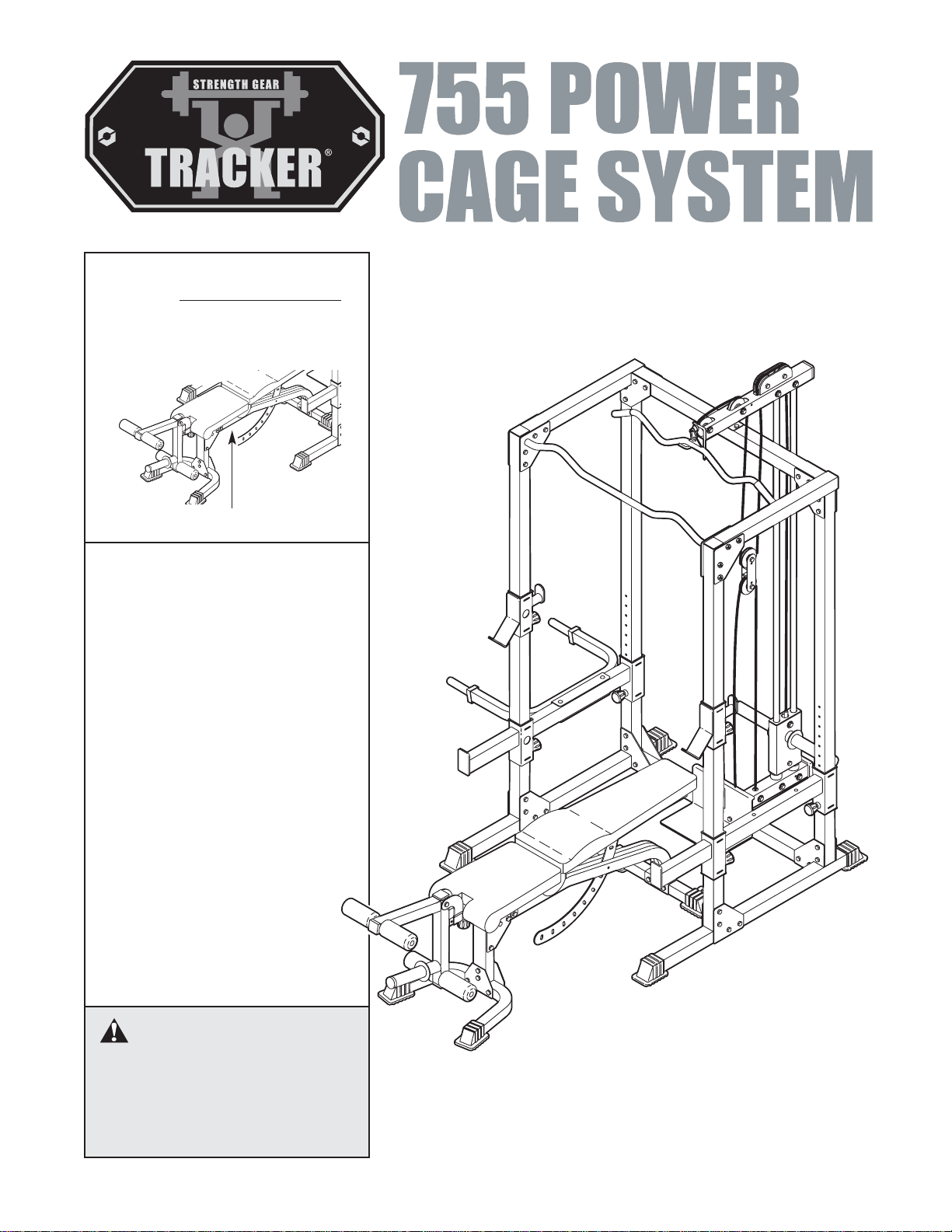
Tracker 755 POWER CAGE SYSTEM User manual
QUESTIONS?
As a manufacturer, we are com-
mitted to providing complete
customer satisfaction. If you
have questions, or if there are
missing parts, we will guarantee
complete satisfaction through
direct assistance from our factory.
TO AVOID UNNECESSARY
DELAYS, PLEASE CALL DIRECT
TO OUR TOLL-FREE CUSTOMER
HOT LINE. The trained techni-
cians on our customer hot line
will provide immediate assis-
tance, free of charge to you.
CUSTOMER HOT LINE:
1-800-999-3756
Mon.–Fri., 6 a.m.–6 p.m. MST
Model No. GLSY26622
Serial No.
Write the serial number in the
space above for reference.
CAUTION
Read all precautions and instruc-
tions in this manual before using
this equipment. Save this manual
for future reference.
Serial Number Decal
USER’S MANUAL
Patent Pending
WARNING DECAL PLACEMENT
2
WARNING DECAL PLACEMENT . . . . . . . . . . . . . . . . . . . . . . . . . . . . . . . . . . . . . . . . . . . . . . . . . . . . . . . . . . 2
IMPORTANT PRECAUTIONS . . . . . . . . . . . . . . . . . . . . . . . . . . . . . . . . . . . . . . . . . . . . . . . . . . . . . . . . . . . . . 3
BEFORE YOU BEGIN . . . . . . . . . . . . . . . . . . . . . . . . . . . . . . . . . . . . . . . . . . . . . . . . . . . . . . . . . . . . . . . . . . . 4
PART IDENTIFICATION CHART . . . . . . . . . . . . . . . . . . . . . . . . . . . . . . . . . . . . . . . . . . . . . . . . . . . . . . . . . . . 5
ASSEMBLY . . . . . . . . . . . . . . . . . . . . . . . . . . . . . . . . . . . . . . . . . . . . . . . . . . . . . . . . . . . . . . . . . . . . . . . . . . . 6
ADJUSTMENTS . . . . . . . . . . . . . . . . . . . . . . . . . . . . . . . . . . . . . . . . . . . . . . . . . . . . . . . . . . . . . . . . . . . . . . 14
EXERCISE GUIDELINES . . . . . . . . . . . . . . . . . . . . . . . . . . . . . . . . . . . . . . . . . . . . . . . . . . . . . . . . . . . . . . . 17
ORDERING REPLACEMENT PARTS . . . . . . . . . . . . . . . . . . . . . . . . . . . . . . . . . . . . . . . . . . . . . . . .Back Cover
LIMITED WARRANTY . . . . . . . . . . . . . . . . . . . . . . . . . . . . . . . . . . . . . . . . . . . . . . . . . . . . . . . . . . . Back Cover
Note: A PART LIST/EXPLODED DRAWING is attached in the center of this manual. Remove the PART
LIST/EXPLODED DRAWING before beginning assembly.
TRACKER, a registered trademark of Galyan’s Nevada Inc., East Main St., Plainfield, IN 46168
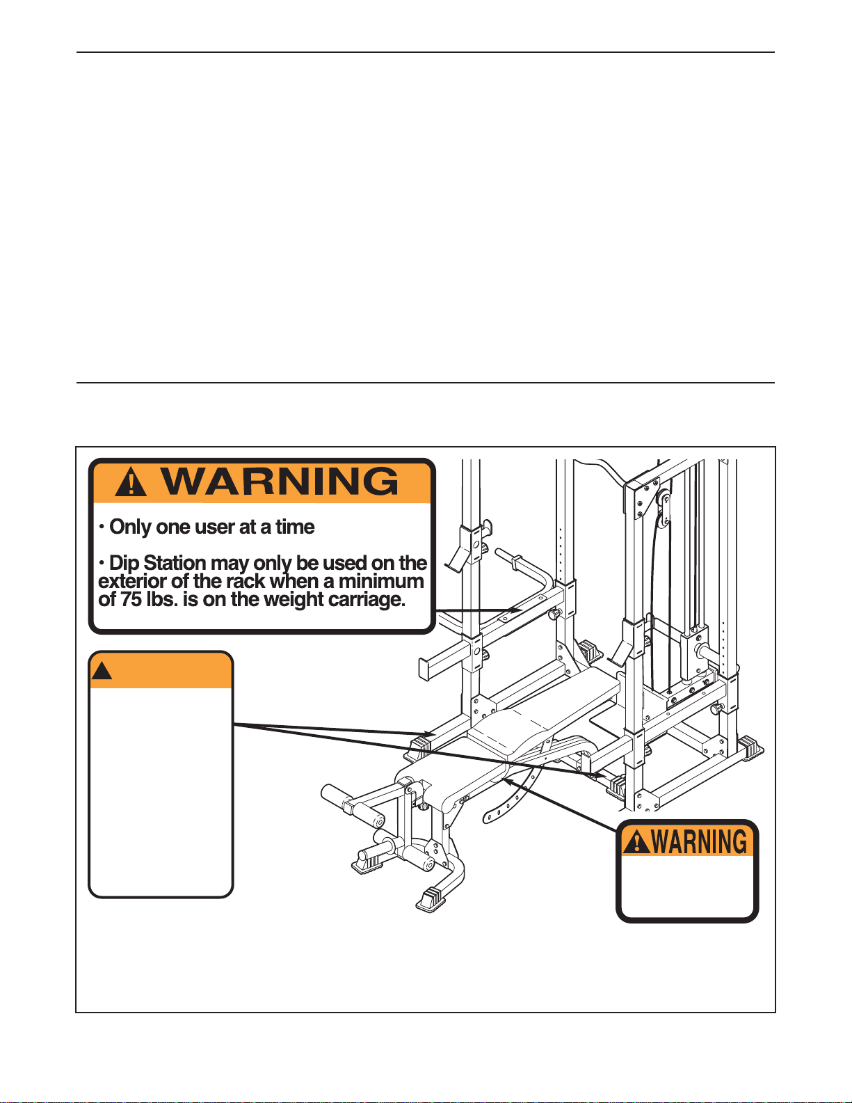
The decals shown here have been placed on
the weight rack and on the bench. If a decal is missing or illegible, call
our Customer Service Department toll-free at 1-800-999-3756, Monday
through Friday, 6 a.m. until 6 p.m. Mountain Time, to order a free replace-
ment decal. Apply the replacement decal in the location shown.
Keep hands and
fingers clear of
this area.
• Misuse of this
product may result in
serious injury.
WARNING
!
• Read user’s manual
and follow all warnings
and operating instruc-
tions prior to use.
• Replace label if
damaged, illegible,
or removed.
• Do not allow children
on or around machine.
TABLE OF CONTENTS
This decal is on
the finger guards
on both sides of
the weight bench.

3
1. Read all instructions in this manual before
using the weight system. Use the weight sys-
tem only as described in this manual.
2. It is the responsibility of the owner to ensure
that all users of the weight system are ade-
quately informed of all precautions.
3. The weight system is intended for home use
only. Do not use the weight system in any
commercial, rental, or institutional setting.
4. Use the weight system only on a level sur-
face. Cover the floor beneath the weight sys-
tem to protect the floor or carpet.
5. Make sure all parts are properly tightened
each time the weight system is used.
Replace any worn parts immediately.
6. Keep children under 12 and pets away from
the weight system at all times.
7. Keep hands and feet away from moving parts.
8. The weight system is designed to support a
maximum user weight of 250 pounds and a
maximum total weight of 550 pounds. Do not
place more than 300 pounds, including the
barbell, on the weight rests. Do not place
more than 150 pounds on the weight carriage
or the leg lever. Note: The weight system
does not include a barbell or weights.
9. Always make sure there is an equal amount
of weight on each end of the barbell.
10. Always set both weight rests and both safety
spotters at the same height.
11. Always secure weights with the weight clips
when they are mounted on the weight car-
riage.
12. Make sure that the cables remain on the pul-
leys at all times. If the cables bind as you are
exercising, stop immediately and make sure
that the cables are on the pulleys.
13. Always wear athletic shoes for foot protec-
tion while exercising.
14. Always exercise with a partner. When you
are performing squat exercises, your partner
should stand behind you to catch the barbell
if you cannot complete a repetition.
15. If you feel pain or dizziness at any time while
exercising, stop immediately and begin cool-
ing down.
16. Always disconnect the lat bar from the
weight system when performing an exercise
that does not require the lat bar.
WARNING:Before beginning this or any exercise program, consult your physician. This
is especially important for persons over the age of 35 or persons with pre-existing health problems.
Read all instructions before using. ICON assumes no responsibility for personal injury or property
damage sustained by or through the use of this product.
WARNING: To reduce the risk of serious injury, read the following important precautions
before using the weight system.
IMPORTANT PRECAUTIONS
4
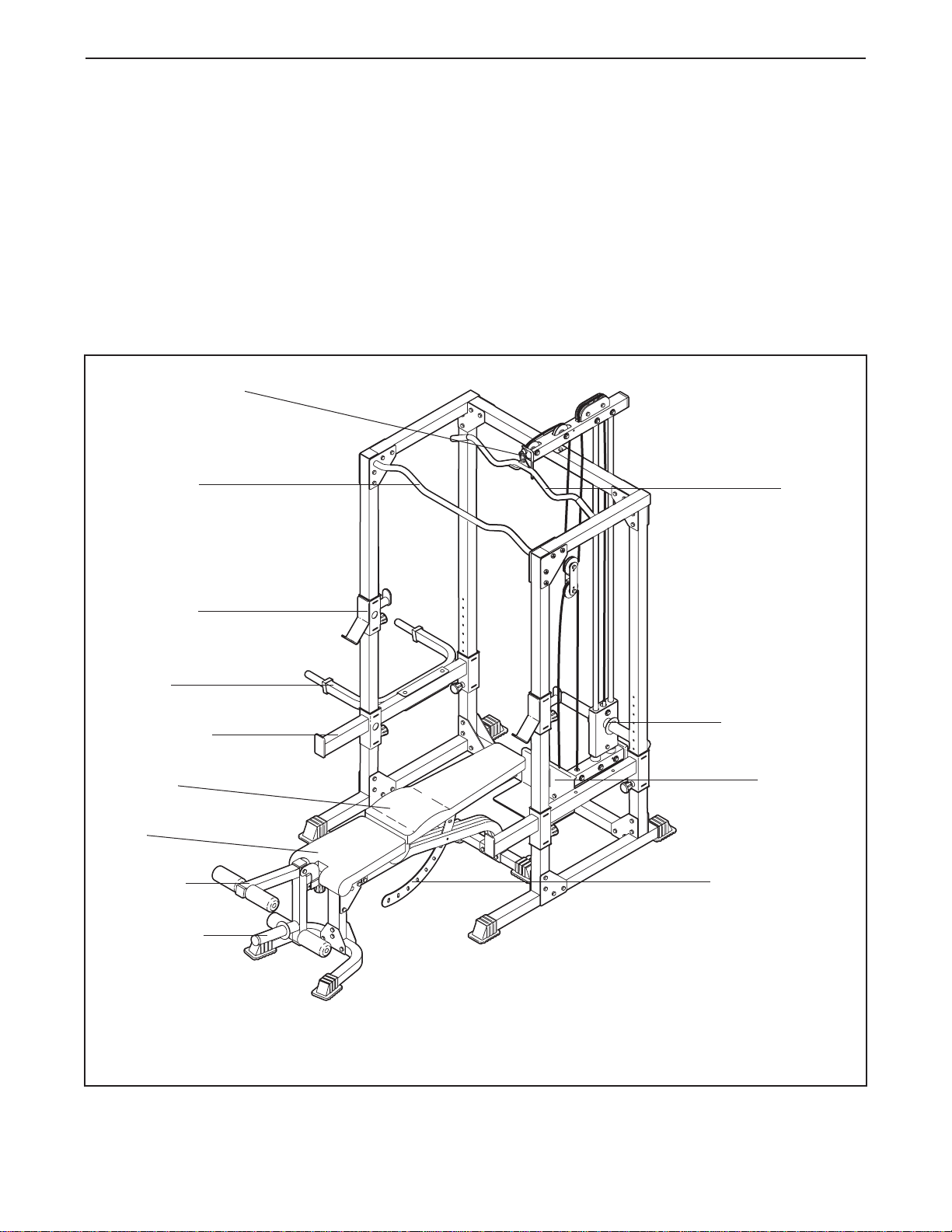
Weight Carriage
High Pulley Station
Lat Bar
Weight Rest
Dip Arm
Safety Spotter
Leg Lever
Weight Tube
Backrest
Seat
Right Side
Left Side
Note: The terms “right side” and “left
side” are determined relative to a per-
son using the rack; they do not corre-
spond to right and left on the drawings
in the manual.
Backrest Bracket
Low Pulley
Station
Thank you for selecting the versatile TRACKER®755
POWER CAGE SYSTEM weight system. The weight
system is designed to help you develop every major
muscle group of the body. Whether your goal is a
shapely figure, dramatic increase in muscle size and
strength, or a healthier cardiovascular system, the
weight system will help you achieve the specific
results you want.
For your benefit, read this manual carefully before
using the weight system. If you have additional ques-
tions, please call our Customer Service Department
toll-free at 1-800-999-3756, Monday through Friday,
6 a.m. until 6 p.m. Mountain Time (excluding holidays).
To help us assist you, please note the product model
number and serial number before calling. The model
number is GLSY26622. The serial number can be
found on a decal attached to the weight system (see
the front cover of this manual).
Before reading further, please review the drawing below
and familiarize yourself with the parts that are labeled.
Chin-up Bar
BEFORE YOU BEGIN
5
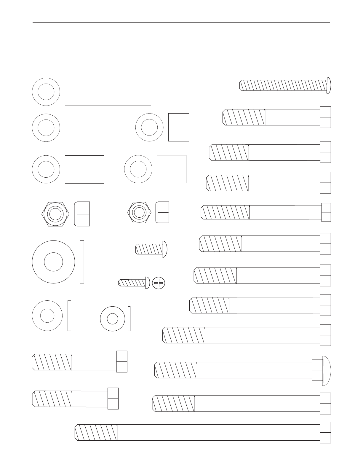
51mm Spacer (39)
28mm Spacer (40)
M10 x 45mm Bolt (32)
M10 x 50mm Bolt (84)
M10 x 65mm Bolt (35)
M6 x 53mm Screw (51)
M10 x 78mm Bolt (31)
M10 x 75mm Bolt (34)
M8 x 72mm Bolt (33)
M10 x 94mm Carriage Bolt (57)
12mm Spacer (88)
M6 Washer (74)
M8 Washer (36)
M10 Washer (37)
M10 Nylon Locknut (29) M8 Nylon Locknut (30)
M10 x 146mm Bolt (66)
M10 x 68mm Bolt (75)
M10 x 58mm Bolt (78)
M10 x 100mm Bolt (81)
M10 x 94mm Bolt (94)
M6 x 16mm Screw (50)
17mm Spacer (83)
23mm Spacer (38)
M4 x 16mm Screw (87)
M10 x 72mm Bolt (96)
PART IDENTIFICATION CHART
Refer to the drawings below to identify small parts used in assembly. The number in parentheses by each draw-
ing is the key number of the part, from the PART LIST in the center of this manual. Note: Some small parts
may have been pre-attached. If a part is not in the parts bag, check to see if it has been pre-attached.
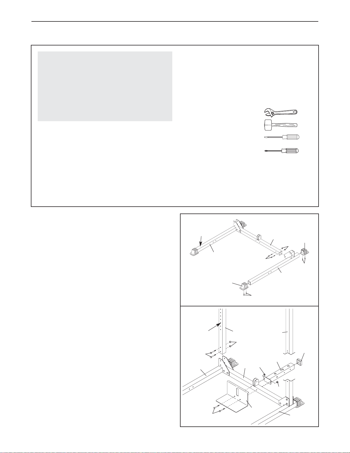
6
Before beginning assembly, carefully read the
following information and instructions:
•Assembly requires two people.
•Place all parts in a cleared area and remove the
packing materials. Do not dispose of the packing
materials until assembly is completed.
•Tighten all parts as you assemble them, unless
instructed to do otherwise.
•As you assemble the weight system, make sure
all parts are oriented as shown in the drawings.
•For help identifying small parts, refer to the
PART IDENTIFICATION CHART on page 5.
The following tools (not included) are required
for assembly:
•Two adjustable wrenches
•One rubber mallet
•One standard screwdriver
•One Phillips screwdriver
•Lubricant, such as grease or petroleum jelly,
and soapy water.
Assembly will be more convenient if you have a
socket set, a set of open-end or closed-end
wrenches, or a set of ratchet wrenches.
Make Things Easier for Yourself
Everything in this manual is designed to ensure
that the weight system can be assembled suc-
cessfully by anyone. However, it is important to
realize that the versatile weight system has
many parts and that the assembly process will
take time. Most people find that by setting aside
plenty of time, assembly will go smoothly.
1
1
Decal 27
27
31
29
87
3
2
87
1. Attach two Large Base Caps (27) to the ends of
the Left Base (3) with four M4 x 16mm Screws
(87).
Attach the Left Base (3) to the Center Base (2)
with two M10 x 78mm Bolts (31) and two M10
Nylon Locknuts (29). Do not tighten the
Locknuts yet.
Repeat this step with the Right Base (1). Make
sure the warning decal is in the indicated
location.
2
12
5
31
31
29
29
29
4
3
85
8
Adjustment
Holes 8
2. Identify the two Rear Uprights (8), which are
shorter than the Front Uprights (not shown).
Attach the Rear Uprights (8) to the Left and Right
Bases (1, 3) using four M10 x 78mm Bolts (31)
and four M10 Nylon Locknuts (29). Do not tight-
en the Locknuts yet. Make sure the Uprights
are oriented with the adjustment holes on the
indicated side near the bottom.
Press a 50mm Square Outer Cap (85) onto the
end of the Weight Guide Base (4).
Orient the Foot Plate (5) and the Weight Guide
Base (4) as shown. Attach the Foot Plate and the
Weight Guide Base to the Center Base (2) using
two M10 x 78mm Bolts (31) and two M10 Nylon
Locknuts (29). Do not tighten the Locknuts yet.
ASSEMBLY
7
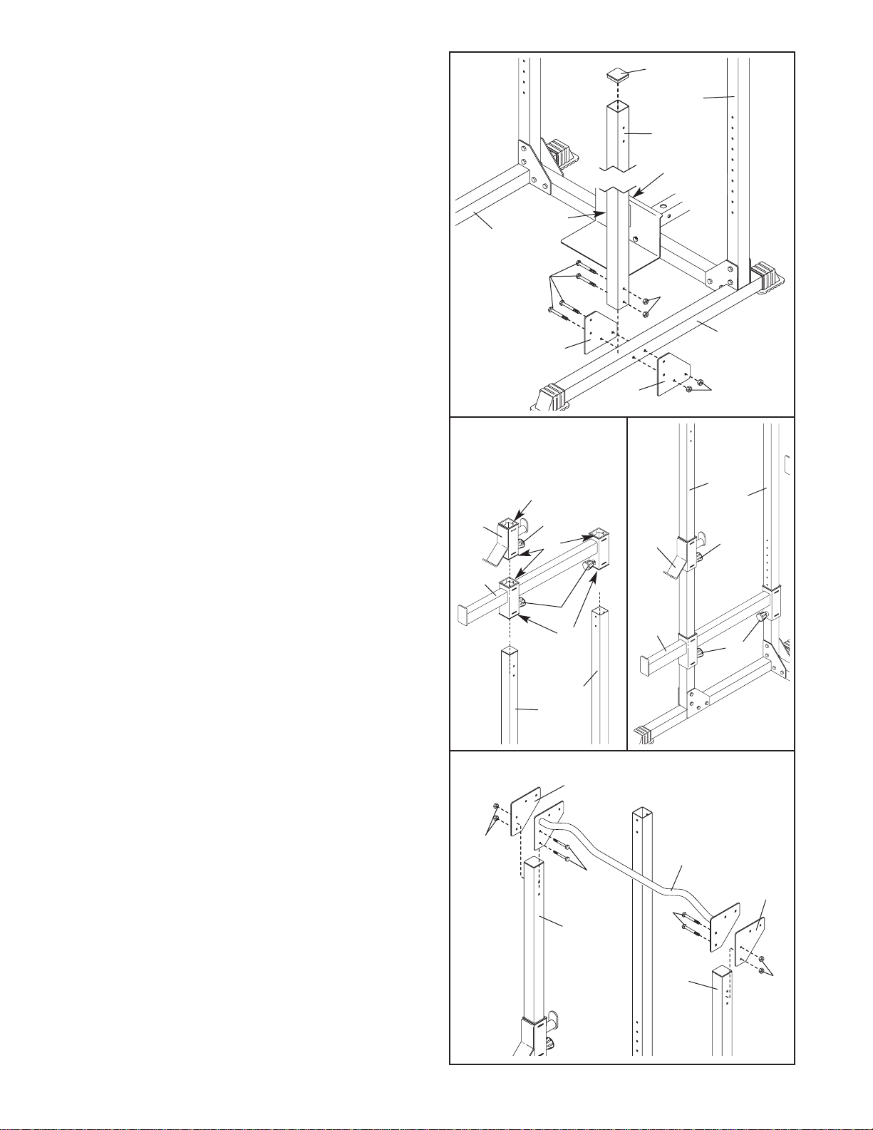
3
4a 4b
4. This step will require two people.
Refer to drawing 4a. Have one person hold out
the Adjustment Knobs (22) on the Right Safety
Spotter (20), while the other person slides the
Safety Spotter down over the right Uprights (7, 8),
as shown. Hold the Adjustment Knob out on the
Right Weight Rest (19), and slide the Weight Rest
onto the Front Upright (7). To avoid breaking the
Square Bushings (21) inside the top and bot-
tom of the Safety Spotter and Weight Rest, be
careful not to catch the Square Bushings on
the edges of the Uprights as they slide on.
Refer to drawing 4b. Secure the Right Safety
Spotter (20) and the Right Weight Rest (19) to the
right Uprights (7, 8) by snapping the three
Adjustment Knobs (22) into adjustment holes in
the Uprights and turning them clockwise until
tight.
Assemble the Left Safety Spotter (not shown) and
Left Weight Rest (not shown) to the left Uprights
(not shown) in the same manner.
Make sure both Safety Spotters and both
Weight Rests are at the same height.
3
1
31 29
29
22
22
7
7
8
8
22
22
20
21
21
21
20
19 19
6
6
7
8
28
3. Tap a 60mm Square Inner Cap (28) into the top
of each of the Front Uprights (7).
Attach a Front Upright (7) and two Rack Joint
Plates (6) to the Left Base (3) using four M10 x
78mm Bolts (31) and four M10 Nylon Locknuts
(29). Make sure that the Front Upright is
turned so the adjustment holes are facing the
Rear Upright (8), the numbers are on the
inside of the rack, and that the holes near the
bottom of the Front Upright and the holes in
the Joint Plates line up. If they do not line up,
turn the Front Upright upside-down. Do not
tighten the Locknuts yet.
Attach the other Front Upright (7) and two
Rack Joint Plates (6) to the Right Base (1) in
the same manner.
5. Attach the Chin-up Bar (13) and two Rack Joint
Plates (6) to the Front Uprights (7) using four
M10 x 78mm Bolts (31) and four M10 Nylon
Locknuts (29). Do not tighten the Locknuts yet.
6
29
29
31
31 6
7
13
7
5
Adjustment
Holes
Numbers

8
8. Set the two Weight Bumpers (18) over the indi-
cated holes in the Weight Guide Base (4). Set the
Weight Carriage (15) on the Weight Bumpers.
Insert the two Weight Guides (9) through the
Weight Carriage (15). Attach the Weight Guides
to the Weight Guide Base (4) using two M8 x
72mm Bolts (33), four M8 Washers (36), and two
M8 Nylon Locknuts (30).
7. Press the two 48mm Round Inner Caps (42) into
the weight tubes on the Weight Carriage (15).
Make sure the Weight Carriage is turned so
the weight tubes are near the top, as shown.
Attach the lower Carriage Bushing (16) to the
Weight Carriage (15) using an M10 x 65mm Bolt
(35), two M10 Washers (37), the 51mm Spacer
(39), and an M10 Nylon Locknut (29).
42
42
15 Weight Tube
35
37
39
37
16
29
6. Press a 60mm Square Inner Cap (28) into the
Left Frame (12). Attach the Left Frame to the left
Uprights (7, 8) using four M10 x 78mm Bolts (31)
and four M10 Nylon Locknuts (29). Do not tight-
en the Locknuts yet.
Assemble the Right Frame (10) on the right
Uprights (7, 8) in the same manner.
Attach the Center Frame (11) to the Right and
Left Frames (10, 12) using four M10 x 78mm
Bolts (31) and four M10 Nylon Locknuts (29).
Tighten the M10 Nylon Locknuts (29) used in
steps 1–6.
29
28
29
31
31
31
31
10
11
Decal
12
29
29
6
7
8
7
8
8
7
15
18 4
36
30
9
33
9
9. Press a 60mm Square Inner Cap (28) into the
end of the Weight Guide Frame (14).
Hold the Weight Guide Frame (14) on top of the
Center Frame (11) and the Weight Guides (9).
Attach the Weight Guides to the Weight Guide
Frame using two M8 x 72mm Bolts (33), four M8
Washers (36), and two M8 Nylon Locknuts (30).
Attach the Weight Guide Frame (14) to the
Center Frame (11) using two M10 x 78mm Bolts
(31), two M10 Washers (37), and two M10 Nylon
Locknuts (29).
31
37
11
14
29
9
33
36
28
36
30

9
10
10. Locate the Long Cable (82) and notice that there
is a ball on one end and eyelet on the other end.
Route the eyelet end of the Long Cable (82) up
under the lat bar rest on the Weight Guide Frame
(14), down through the indicated hole, back up
through the next hole, and then down between
the Weight Guides (9) as shown.
11.Insert the end of the Long Cable (82) into the
hole in the center of the Weight Carriage (15).
Attach the Cable using an M10 x 65mm Bolt (35),
two M10 Washers (37), two 23mm Spacers (38),
and an M10 Nylon Locknut (29).
12 Lift the Long Cable (82) in the location shown.
Attach two Pulleys (24) inside the bracket on the
Weight Guide Frame (14) using two M10 x 50mm
Bolts (84) and two M10 Nylon Locknuts (29).
82
11
15
12
29
84
24 82
14
35
37
37
29
9
14
Lat Bar
Rest
82
38
38
13
82 14
34
29
37
83
24
13. Lift the Long Cable (82) in the location shown.
Attach two Pulleys (24) inside the Weight Guide
Frame (14) using two M10 x 75mm Bolts (34),
four M10 Washers (37), four 17mm Spacers (83),
and two M10 Nylon Locknuts (29).
37
37
37
83
83
83

10
24
229
15
29
17
17
32
2423
82
25
23
14. Pull the Long Cable (82) down in the indicated
location, so there is no slack at the ends of the
Cable.
Locate the Short Cable (25), which has a ball on
one end. Insert the eyelet end of the Cable
through the hole in the Foot Plate (5) and into the
indicated hole in the Weight Guide Base (4).
Attach the Cable using an M10 x 75mm Bolt (34),
two M10 Washers (37), two 28mm Spacers (40),
and an M10 Nylon Locknut (29).
Rest the Short Cable (25) in the bracket on the
Center Base (2). Attach the Pulley inside the
bracket using an M10 x 45mm Bolt (32) and an
M10 Nylon Locknut (29).
15. Wrap the Long Cable (82) around a Pulley (24)
as shown. Attach the Pulley and a Cable Trap
(23) to the two Pulley Plates (17) using an M10 x
45mm Bolt (32) and an M10 Nylon Locknut (29).
Wrap the Short Cable (25) around a Pulley (24)
as shown. Attach the Pulley and a Cable Trap
(23) to the Pulley Plates (17) using an M10 x
45mm Bolt (32) and an M10 Nylon Locknut (29).
Make sure that the M10 x 45mm Bolts (32) are
inserted through the highest and lowest holes
in the Pulley Plates (17), and that the Cables
(25, 82) are between the Cable Traps (23) and
the Pulleys (24).
32
534
37
37
40 4
40
25
82
14
16
45
47
47
16. Wet the ends of the Lat Bar (45) with soapy
water. Slide the Handgrips (47) onto the ends of
the Lat Bar.
Make sure that all parts of the weight rack are
properly tightened. In addition, pull each cable
a few times to make sure the cables move
smoothly over the pulleys. If the cables do not
move smoothly, locate and correct the prob-
lem. When weights are used, the cables may
be damaged if they are incorrectly routed.
11
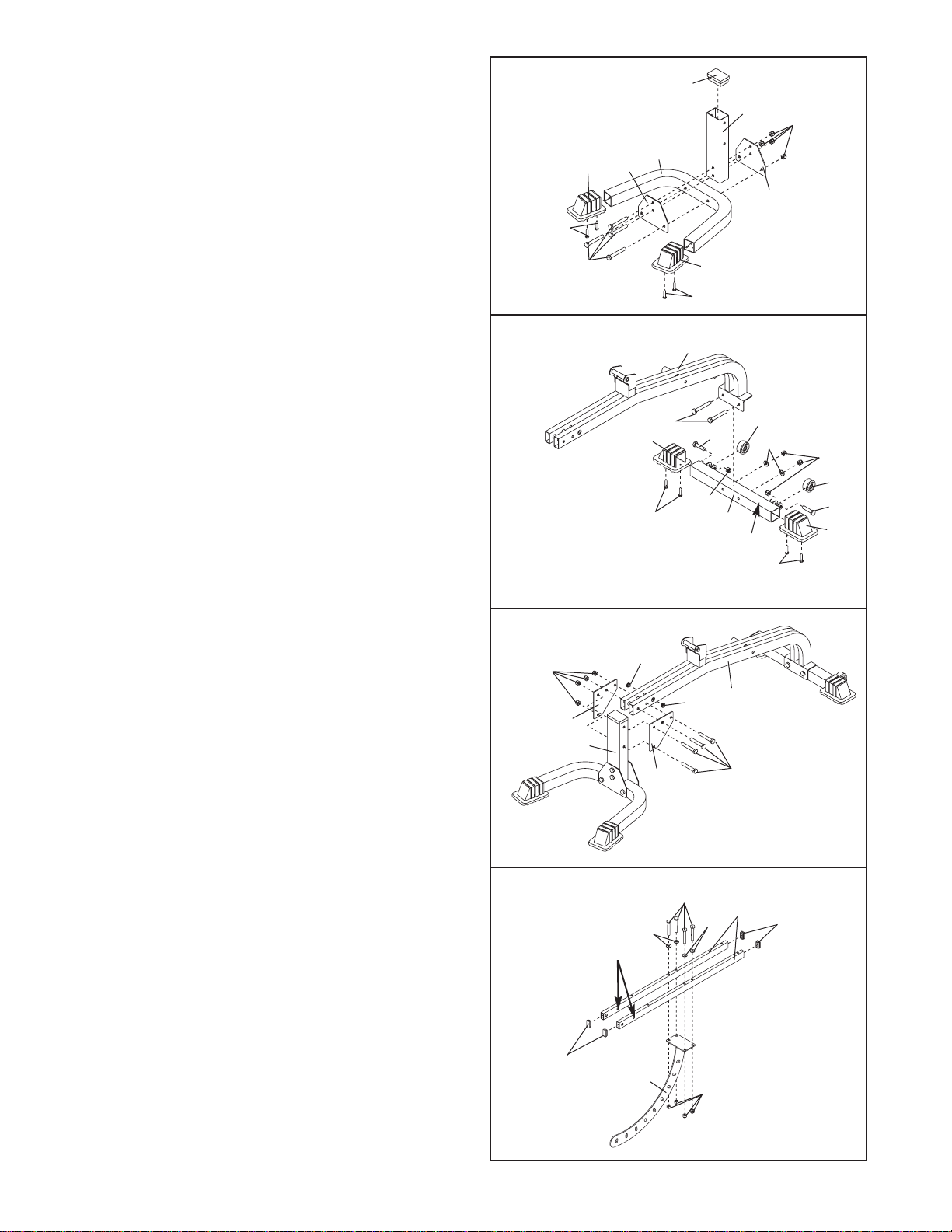
17. Attach two Small Base Caps (65) to the Bench
Base (53) with for M4 x 16mm Screws (87).
Press a 50mm x 70mm Inner Cap (76) into the
Bench Leg (48).
Attach the Bench Leg (48) to the Bench Base
(53) with four M10 x 72mm Bolts (96), two Bench
Base Joint Plates (64), and four M10 Nylon
Locknuts (29). Do not tighten the Locknuts yet.
17
64
64 53
76 48
65
65
87
87
96
29
18. Attach two Small Base Caps (65) to the Stabilizer
(58) with four M4 x 16mm Screws (87).
Attach the two Wheels (79) to the Stabilizer (58)
with two M10 x 45mm Bolts (32) and two M10
Nylon Locknuts (29). Do not overtighten the
Locknuts; the Wheels must be able to roll easi-
ly.
Attach the Bench Frame (52) to the Stabilizer (58)
with two M10 x 68mm Bolts (75), two M10
Washers (37), and two M10 Nylon Locknuts (29).
Make sure the decal is in the indicated posi-
tion. Do not tighten the Locknuts yet.
18
65
58
Decal
79
32
75
29
29
37
52
79
32
87
87
65
19. Press two Bushings (77) into the Bench Frame
(52).
Attach the Bench Frame (52) to the Bench Leg
(48) with four M10 x 94mm Bolts (94), two Bench
Joint Plates (63), and four M10 Nylon Locknuts
(29). Do not tighten the Locknuts yet.
19
48
94
77
52
29
63
63
77
20. Press four 20mm x 40mm Inner Caps (72) into
the ends of the two Backrest Frames (71).
Attach the Backrest Frames (71) to the Backrest
Bracket (49) with four M10 x 58mm Bolts (78),
four M10 Washers (37), and four M10 Nylon
Locknuts (29). Make sure the Backrest Frames
are oriented as shown. The Backrests Frames
must be parallel, with the indicated holes
aligned.
20
72
37
78
49
Holes
72
29
37 71

12
21. Attach the Backrest (60) to the Backrest Frames
(71) with four M6 x 53mm Bolts (51) and four M6
Washers (74). Note: If the four Bolts cannot be
inserted into the Backrest properly, go back to
step 20 and readjust the Backrest Frames.
21
71
51
74
74
60
51
22. Press four Bushings (77) into the Backrest
Frames (71) as shown.
Secure the Backrest Knob (73) to the Bench
Frame (52). Pull the Knob out as far as it will go.
Slide the Backrest Bracket (49) between the
Bench Frame tubes and engage the Knob into a
hole in the Bracket.
Attach the Backrest Frames (71) and two Guard
Plates (56) to the Bench Frame (52) with an M10
x 146mm Bolt (66), two M10 Washers (37), and
an M10 Nylon Locknut (29). Make sure the
decals are on the outside of the Guard Plates.
Do not overtighten the Locknut; the Backrest
Frames and Guard Plates must be able to
pivot easily.
22
29
37
77
73
37
66
52
56
60
71
23. Press a 38mm x 50mm Inner Cap (86) into the
indicated end of the Seat Frame (67). Press two
Bushings (77) into the Seat Frame as shown.
Attach the Pivot Bracket (43) to the Seat Frame
(67) with an M10 x 75mm Bolt (34) and an M10
Nylon Locknut (29). Do not overtighten the
Locknut; the Pivot Bracket must be able to
pivot easily.
Attach the Seat (59) to the Seat Frame (67) with
two M6 x 16mm Screws (50), an M6 x 53mm Bolt
(51), and an M6 Washer (74).
23
43 34
67 86
59
77
77
29
51
50
74
24. Press two Bushings (77) into the Seat Frame (67)
as shown.
Attach the Seat Frame (67) to the Backrest
Frames (71) and Guard Plates (56) with an M10 x
146mm Bolt (66), two 12mm Spacers (88), and
an M10 Nylon Locknut (29). Do not overtighten
the Locknut; the Seat Frame must be able to
pivot easily.
Attach the Pivot Bracket (43) to the Bench Frame
(52) with an M10 x 100mm Bolt (81) and an M10
Nylon Locknut (29). Do not overtighten the
Locknut; the Pivot Bracket must be able to
pivot easily.
24
29
81
88
29 67 77
52
49
Hole
Decal
43 66
71
56

13
25. Press three 50mm Square Inner Caps (26) into
the Leg Lever (62). Press a 48mm Round Inner
Cap (42) into the tube on the Leg Lever.
Slide the two Pad Tubes (61) into the Leg Lever
(62). Slide four Foam Pads (69) onto the ends of
the Pad Tubes. Press four 19mm Round Inner
Caps (70) into the ends of the Pad Tubes.
26. Press two Bushings (77) into the Leg Lever
Bracket (41) as shown.
Attach the Leg Lever (62) to the Leg Lever
Bracket (41) with an M10 x 78mm Bolt (31) and
an M10 Nylon Locknut (29). Do not overtighten
the Locknut; the Leg Lever must be able to
pivot easily.
Loosen the Seat Knob (22). Secure the Leg
Lever Bracket (41) in the end of the Seat Frame
(67) with the Knob.
27. Press a 45mm Square Inner Cap (95) into the
bottom of the Curl Post (55).
Attach the Curl Pad (54) to the Curl Post (55)
with two M6 x 16mm Screws (50).
25 26
26
26
42
69
69
70
70
69
62
61
26 67
22
77
41
29
62 77
31
27
28
54
55
95
50
68
80 80
47
47
28. Press the two Handgrip Bushings (80) onto the
Dip Arm (68). Slide two Handgrips (47) onto the
Dip Arm.
29. Make sure all parts are properly tightened
before you use the weight system. The use of
the remaining parts will be explained in
ADJUSTMENTS on the following page.

14
This section explains how the weight system can be adjusted. See the EXERCISE GUIDELINES on page 17 for
information about how to get the most benefit from your exercise program. See the included exercise guide for infor-
mation about how to perform a variety of exercises.
Make sure all parts are properly tightened each time the weight system is used. Replace any worn parts immediate-
ly. The weight system can be cleaned with a damp cloth and a mild, non-abrasive detergent. Do not use solvents.
60
73
49
62
55
22
54
62 41
67
ATTACHING THE LEG LEVER OR CURL PAD
To use the Leg Lever (62), insert the Leg Lever
Bracket (41) into the Seat Frame (67). Secure the
Bracket with the Adjustment Knob (22).
To use the Curl Pad (54), insert the Curl Post (55)
into the Seat Frame (67). Secure the Curl Post with
the Adjustment Knob (22).
ADJUSTMENTS
ADJUSTING THE BACKREST
To adjust the position of the Backrest (60), pull the
Bench Knob (73) out as far as it will go. Move the
Backrest to the desired position, and engage the
Knob into a hole in the Backrest Bracket (49).
ADDING WEIGHT TO THE LEG LEVER
To use the Leg Lever (62), slide the desired amount
of weight (not included) onto the tube on the Leg
Lever.
WARNING:Do not place more than
150 pounds on the Leg Lever (62).
15
USING THE WEIGHT RESTS AND SAFETY
SPOTTERS
Before beginning an exercise, move the Weight Rests
(19, 89) and the Safety Spotters (20, 90) to sets of
holes in the Uprights (7, 8) that are best suited for
that exercise. Do this by turning the Adjustment
Knobs (22) counterclockwise until loose. Pull the
Knobs out and slide the Weight Rests or the Safety
Spotters to the desired heights. Engage the Knobs
into the adjustment holes in the Uprights and turn the
Knobs clockwise until tight.
The selected holes for the Safety Spotters (20, 90)
should represent the lowest point to which you want
the barbell to go during the exercise. The selected
holes for the Weight Rests (19, 89) should be at a
comfortable height for lifting and replacing the barbell.
Perform the exercise as shown on the accompanying
exercise guide. Note: Make sure the Adjustment
Knobs (22) are fully tightened.
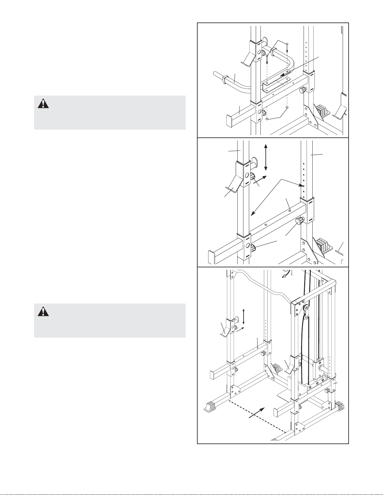
ATTACHING THE DIP ARM
To attach the Dip Arm (68), first move a Safety Spotter
(20 or 90) to the highest position possible (see USING
THE WEIGHT RESTS AND SAFETY
SPOTTERS, below). Attach the Dip Arm to the outside
of the Safety Spotter with two M10 x 94mm Carriage
Bolts (57) and two M10 Nylon Locknuts (29). Make
sure the warning decal is in the indicated location.
WARNING:Always set both Weight
Rests (19, 89) at the same height and both
Safety Spotters (20, 90) at the same height.
19
7
68
20
57
Decal
29
8
Adjustment
Holes
19
89
90
20
22
22
WARNING:Always set 75 pounds
on the Weight Carriage (not shown) before
using the Dip Arm (68).
SETTING UP FOR SQUAT EXERCISES
Squat exercises should be performed inside the rack
(behind the dotted line in the picture). When perform-
ing squat exercises, set the Weight Rests (19, 89)
and the Safety Spotters (20, 90) at a comfortable
height in the manner describe in USING THE
WEIGHT RESTS AND SAFETY SPOTTERS above.
Squat
Area
20
16
ADDING WEIGHTS TO THE WEIGHT CARRIAGE
To use the high or low pulley station, slide the desired
amount of weight (not included) onto the weight tubes
on the Weight Carriage (15). Secure the weights with
Weight Clips (91).
91
15
Weight
Tube
WARNING:Do not place more than
150 pounds on the Weight Carriage (15).
Always place the same amount of weight on
each side of the Weight Carriage, and secure
with the Weight Clips (91).
ATTACHING THE LAT BAR TO THE HIGH PULLEY
STATION OR THE LOW PULLEY STATION
To use the high pulley station or the low pulley sta-
tion, first place the desired weights on the weight car-
riage (see ADDING WEIGHTS TO THE WEIGHT
CARRIAGE above). Next, attach the Lat Bar (45) to
either Cable (25) with a Cable Clip (46).
45
46
25
WARNING: Always disconnect the
Lat Bar (45) when performing an exercise that
does not require using the Lat Bar.
29
17
17
32
2423
23
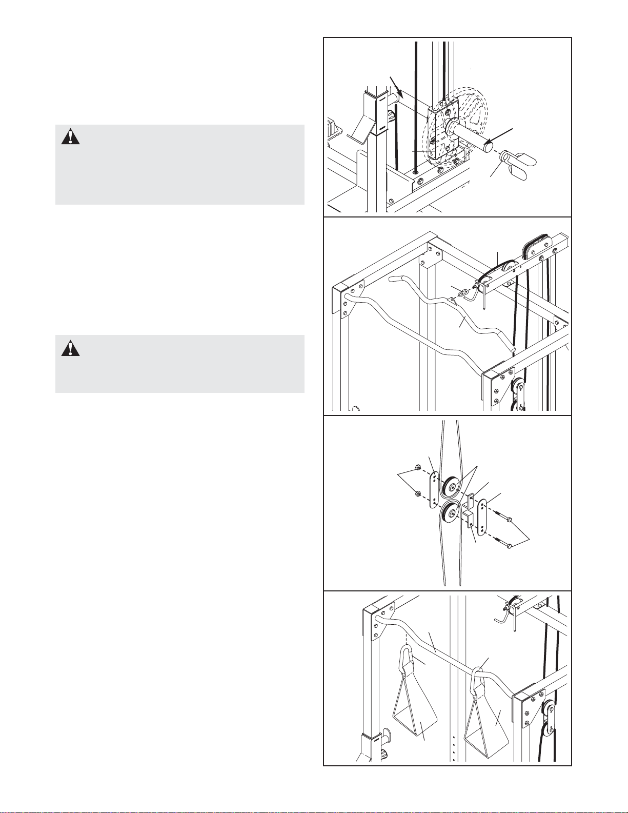
TIGHTENING THE CABLES
Woven cable, the type of cable used on the weight
rack, can stretch slightly after it is first used. If there is
slack in the cables, tighten them as described below.
Remove the M10 x 45mm Bolt (32) and the M10
Nylon Locknut (29) attaching the lower Pulley (24)
and Cable Trap (23) to the two Pulley Plates (17).
Reattach the lower Pulley and Cable Trap to the high-
er holes in the Pulley Plates using the Bolt and Nylon
Locknut.
If moving just the lower Pulley (24) does not suffi-
ciently tighten the cables, you can also move the
upper Pulley down one set of holes in the Pulley
Plates (17).
93
93
13
92 92
USING THE AB SLING
To use the Ab Slings (93), use the Large Cable Clips
(92) to attach them to the Chin-up Bar (13).
Weight
Tube

17
EXERCISE GUIDELINES
THE FOUR BASIC TYPES OF WORKOUTS
Muscle Building
To increase the size and strength of your muscles,
push them close to their maximum capacity. Your mus-
cles will continually adapt and grow as you progres-
sively increase the intensity of your exercise. You can
adjust the intensity level of an individual exercise in
two ways:
• by changing the amount of weight used
• by changing the number of repetitions or sets per-
formed. (A “repetition” is one complete cycle of an
exercise, such as one sit-up. A “set” is a series of
repetitions.)
The proper amount of weight for each exercise
depends upon the individual user. You must gauge
your limits and select the amount of weight that is right
for you. Begin with 3 sets of 8 repetitions for each
exercise you perform. Rest for 3 minutes after each
set. When you can complete 3 sets of 12 repetitions
without difficulty, increase the amount of weight.
Toning
You can tone your muscles by pushing them to a mod-
erate percentage of their capacity. Select a moderate
amount of weight and increase the number of repeti-
tions in each set. Complete as many sets of 15 to 20
repetitions as possible without discomfort. Rest for 1
minute after each set. Work your muscles by complet-
ing more sets rather than by using high amounts of
weight.
Weight Loss
To lose weight, use a low amount of weight and
increase the number of repetitions in each set.
Exercise for 20 to 30 minutes, resting for a maximum
of 30 seconds between sets.
Cross Training
Cross training is an efficient way to get a complete and
well-balanced fitness program. An example of a bal-
anced program is:
• Plan weight training workouts on Monday,
Wednesday, and Friday.
• Plan 20 to 30 minutes of aerobic exercise, such as
cycling or swimming, on Tuesday and Thursday.
• Rest from both weight training and aerobic exercise
for at least one full day each week to give your body
time to regenerate.
The combination of weight training and aerobic exer-
cise will reshape and strengthen your body, plus devel-
op your heart and lungs.
PERSONALIZING YOUR EXERCISE PROGRAM
Determining the exact length of time for each workout,
as well as the number of repetitions or sets completed,
is an individual matter. It is important to avoid overdo-
ing it during the first few months of your exercise pro-
gram. You should progress at your own pace and be
sensitive to your body’s signals. If you experience pain
or dizziness at any time while exercising, stop immedi-
ately and begin cooling down. Find out what is wrong
before continuing. Remember that adequate rest and a
proper diet are important factors in any exercise pro-
gram.
WARMING UP
Begin each workout with 5 to 10 minutes of stretching
and light exercise to warm up. Warming up prepares
your body for more strenuous exercise by increasing
circulation, raising your body temperature and deliver-
ing more oxygen to your muscles.
WORKING OUT
Each workout should include 6 to 10 different exercis-
es. Select exercises for every major muscle group,
emphasizing areas that you want to develop most. To
give balance and variety to your workouts, vary the
exercises from session to session.
Schedule your workouts for the time of day when your
energy level is the highest. Each workout should be
followed by at least one day of rest. Once you find the
schedule that is right for you, stick with it.
EXERCISE FORM
Maintaining proper form is an essential part of an
effective exercise program. This requires moving
through the full range of motion for each exercise, and
moving only the appropriate parts of the body.
Exercising in an uncontrolled manner will leave you
feeling exhausted. On the exercise guide accompany-
ing this manual you will find photographs showing the
correct form for several exercises, and a list of the
muscles affected. Refer to the muscle chart on page
18 to find the names of the muscles.
The repetitions in each set should be performed
smoothly and without pausing. The exertion stage of
each repetition should last about half as long as the
return stage. Proper breathing is important. Exhale
during the exertion stage of each repetition and inhale
during the return stroke. Never hold your breath.

18
Rest for a short period of time after each set. The
ideal resting periods are:
• Rest for three minutes after each set for a muscle
building workout.
• Rest for one minute after each set for a toning work-
out.
• Rest for 30 seconds after each set for a weight loss
workout.
Plan to spend the first couple of weeks familiarizing
yourself with the equipment and learning the proper
form for each exercise.
COOLING DOWN
End each workout with 5 to 10 minutes of stretching.
Include stretches for both your arms and legs. Move
slowly as you stretch and do not bounce. Ease into
each stretch gradually and go only as far as you can
without strain. Stretching at the end of each workout
is an effective way to increase flexibility.
STAYING MOTIVATED
For motivation, keep a record of each workout. The
chart on page 19 of this manual can be photocopied
and used to schedule and record your workouts. List
the date, the exercises performed, the weight used,
and the numbers of sets and repetitions completed.
Record your weight and key body measurements at
the end of every month. Remember, the key to
achieving the greatest results is to make exercise a
regular and enjoyable part of your everyday life.
MUSCLE CHART
A. Sternomastoid (neck)
B. Pectoralis Major (chest)
C. Biceps (front of arm)
D. Obliques (waist)
E. Brachioradials (forearm)
F. Hip Flexors (upper thigh)
G. Abductor (outer thigh)
H. Quadriceps (front of thigh)
I. Sartorius (front of thigh)
J. Tibialis Anterior (front of calf)
K. Soleus (front of calf)
L. Rectus Abdominus (stomach)
M. Adductor (inner thigh)
N. Trapezius (upper back)
O. Rhomboideus (upper back)
P. Deltoid (shoulder)
Q. Triceps (back of arm)
R. Latissimus Dorsi (mid back)
S. Spinae Erectors (lower back)
T. Gluteus Medius (hip)
U. Gluteus Maximus (buttocks)
V. Hamstring (back of leg)
W. Gastrocnemius (back of calf)
N
O
P
Q
R
S
T
U
W
V
M
L
J
G
F
H
I
K
E
C
D
B
A

19
MONDAY
Date:
/ /
EXERCISE WEIGHT SETS REPS
EXERCISE WEIGHT SETS REPS
EXERCISE WEIGHT SETS REPS
AEROBIC EXERCISE
AEROBIC EXERCISE
TUESDAY
Date:
/ /
WEDNESDAY
Date:
/ /
THURSDAY
Date:
/ /
FRIDAY
Date:
/ /
Make photocopies of this page for scheduling and recording your workouts.

Note: “#” indicates a non-illustrated part. Specifications are subject to change without notice. See the back
cover of the user’s manual for information about ordering replacement parts.
Key No. Qty. Description Key No. Qty. Description
11Right Base
21Center Base
31Left Base
41Weight Guide Base
51Foot Plate
66Rack Joint Plate
72Front Upright
82Rear Upright
92Weight Guide
10 1 Right Frame
11 1 Center Frame
12 1 Left Frame
13 1 Chin-up Bar
14 1 Weight Guide Frame
15 1 Weight Carriage
16 2 Carriage Bushing
17 2 Pulley Plate
18 2 Weight Bumper
19 1 Right Weight Rest
20 1 Right Safety Spotter
21 12 Square Bushing
22 7 Adjustment Knob
23 2 Cable Trap
24 7 Pulley
25 1 Short Cable
26 3 50mm Square Inner Cap
27 4 Large Base Cap
28 5 60mm Square Inner Cap
29 69 M10 Nylon Locknut
30 4 M8 Nylon Locknut
31 37 M10 x 78mm Bolt
32 5 M10 x 45mm Bolt
33 4 M8 x 72mm Bolt
34 4 M10 x 75mm Bolt
35 2 M10 x 65mm Bolt
36 8 M8 Washer
37 20 M10 Washer
38 2 23mm Spacer
39 1 51mm Spacer
40 2 28mm Spacer
41 1 Leg Lever Bracket
42 3 48mm Round Inner Cap
43 1 Pivot Bracket
44 1 Strap
45 1 Lat Bar
46 2 Cable Clip
47 4 Handgrip
48 1 Bench Leg
49 1 Backrest Bracket
50 4 M6 x 16mm Screw
51 5 M6 x 53mm Bolt
52 1 Bench Frame
53 1 Bench Base
54 1 Curl Pad
55 1 Curl Post
56 2 Guard Plate
57 2 M10 x 94mm Carriage Bolt
58 1 Stabilizer
59 1 Seat
60 1 Backrest
61 2 Pad Tube
62 1 Leg Lever
63 2 Bench Joint Plate
64 2 Bench Base Joint Plate
65 4 Small Base Cap
66 2 M10 x 146mm Bolt
67 1 Seat Frame
68 1 Dip Arm
69 4 Foam Pad
70 4 19mm Round Inner Cap
71 2 Backrest Frame
72 4 20mm x 40mm Inner Cap
73 1 Bench Knob
74 5 M6 Washer
75 2 M10 x 68mm Bolt
76 1 50mm x 70mm Inner Cap
77 12 Bushing
78 4 M10 x 58mm Bolt
79 2 Wheel
80 2 Handgrip Bushing
81 1 M10 x 100mm Bolt
82 1 Long Cable
83 4 17mm Spacer
84 2 M10 x 50mm Bolt
85 1 50mm Square Outer Cap
86 1 38mm x 50mm Inner Cap
87 16 M4 x 16mm Screw
88 2 12mm Spacer
89 1 Left Weight Rest
90 1 Left Safety Spotter
91 2 Weight Clip
92 2 Large Cable Clips
93 2 Ab Sling
94 4 M10 x 94mm Bolt
95 1 45mm Square Inner Cap
96 4 M10 x 72mm Bolt
#1Allen Wrench
#1User’s Manual
#1Exercise Guide
PART LIST—Model No. GLSY26622 R1003A
This manual suits for next models
1
Table of contents
Other Tracker Fitness Equipment manuals
Popular Fitness Equipment manuals by other brands

Sunny Health & Fitness
Sunny Health & Fitness SF-BH6422 user manual

Sport-thieme
Sport-thieme 273 0905 User manual and instructions

Torque
Torque TANK M1 Assembly guide

NordicTrack
NordicTrack NTCCXC80180 user manual

York
York B500 owner's manual
 How to assemble")
Balanced Body
Balanced Body Trapeze Table (Cadillac) How to assemble


