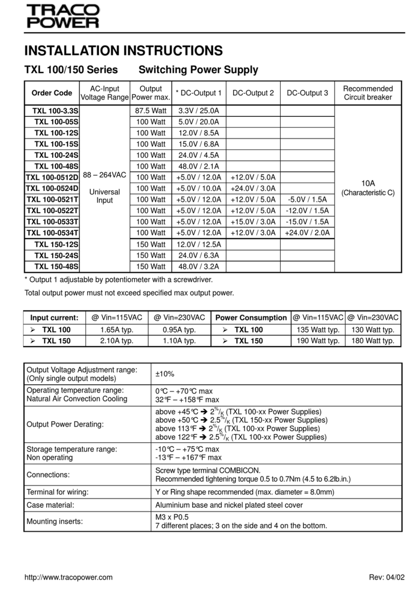
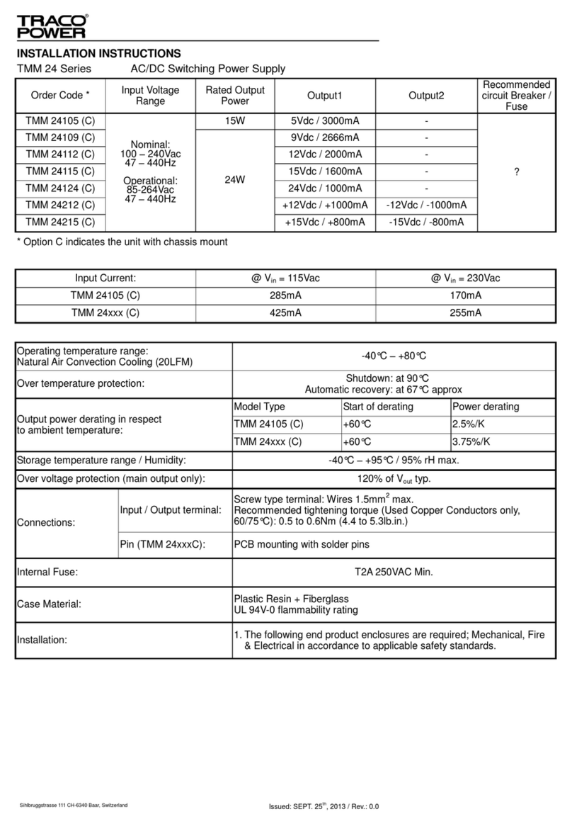
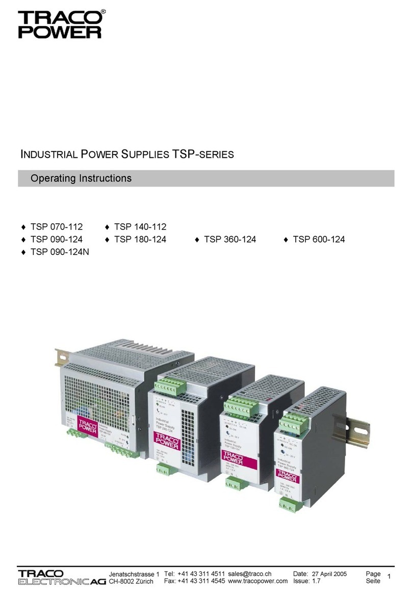
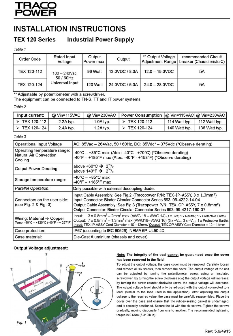
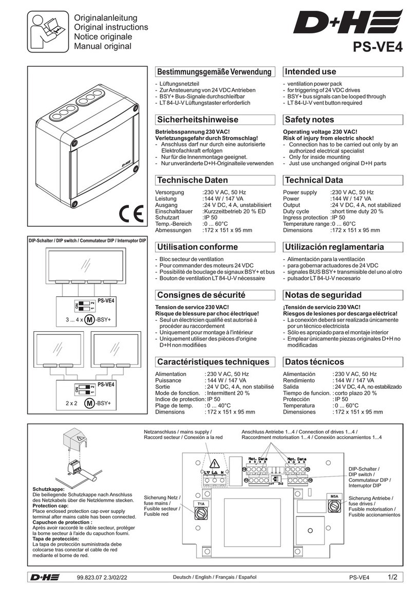
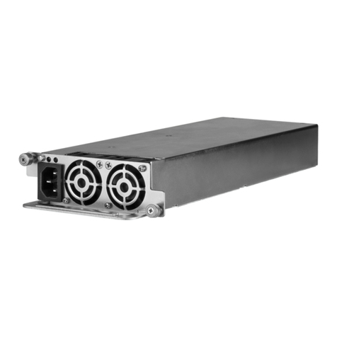
TracoPower TSP SERIES User manual

http://www.tracopower.com Page 1 of 8
TSP 070-112 TSP 140-112
TSP 090-124(N) TSP 180-124 TSP 360-124 TSP 600-124
TSP 090-148 TSP 180-148 TSP 360-148 TSP 600-148
Operating Instructions
INDUSTRIAL POWER SUPPLIES TSP-SERIES

English
http://www.tracopower.com Page 2 of 8
Disclaimer:
Before installing and using the TSP unit read the safety and installation instructions provided with the unit.
1. Mechanical Mounting
To fix unit on the DIN-rail, hook top part of clip on DIN-rail, push down- (see Fig 2.1) and inwards (see Fig 2.2) until you hear a clipping sound.
To remove the unit, pull the latch of the clip with the aid of an insulated flat head screwdriver (see Fig 2.3). When clip has cleared bottom DIN
rail remove the screwdriver from recess. Lift the unit off DIN-rail. See Fig 2.4.
Wall mounting or chassis mounting can be achieved by use of optional mounting brackets TSP-WMK01 (1 bracket) for TSP 070, TSP 090, TSP
140 & TSP 180 or TSP-WMK02 (2 brackets) for TSP 360 & TSP 600 – see datasheet page 9. Remove the DIN-clips by removing the screw and
place the mounting brackets in the same place as the DIN-clips. Use the countersink screws which are included with the wall mounting kit (1
countersink screw with TSP-WMK01 and 2 countersink screws with TSP-WMK02) to fix the mounting brackets on the TSP power supply
(tightening torque 0.8-0.9Nm).
2. Electrical Connections
2.1 Wire and Cable Requirements
To achieve a reliable and shockproof connection strip the connecting ends according the installation manual. If flexible wires are used the wires
have to be terminated. (e.g. by using ferrules).
2.2 Connecting cables
The devices are equipped with COMBICON plug connectors (TSP 070-112, TSP 090-1xx, TSP 140-112, TSP 180-1xx and TSP 360-1xx) or
COMBICON connector (TSP 600-1xx). This reliable and easy-to-assemble connection method enables a fast connection of devices and a
visible isolation of the electrical connection if necessary.
2.2.1 Input (Fig. 4.1, Fig 4.2, Fig 4.3 and Fig. 4.4 Connector J1):
2.2.2 Output (Fig. 4.1, Fig 4.2, Fig 4.3 and Fig. 4.4 Connector J2):
All output terminals should be connected to the load.
2.2.3 Floating contacts (Fig. 4.1, Fig 4.2, Fig 4.3 Connector J2; Fig. 4.4 Connector J5):
For heavily inductive loads such as relay, a suitable protection circuit (e.g. damping diode) is necessary.
2.2.4 Active signal output (Fig. 4.1, Fig 4.2, Fig 4.3 Connector J2; Fig. 4.4 Connector J5):
3. Function
3.1 Signalling
The two DC-OK outputs are for enabling monitoring of the functions of the power supply. A floating signal contact and an active DC-OK signal
are available.
The DC-OK LED also enables a visual evaluation of the function of the power supply directly on site: green – normal operation or red – output
failure if input is still present.
The DC-OK signal is decoupled from the power output. It is thus not possible for parallel-switched devices to provide external supply. The DC-
OK signal can be directly connected to a logic input for evaluation.
Signal loop: The active DC-OK and floating contact DC-Ok can be easily combined.
Example: Monitoring of two devices.
Use the active signal output of device 1 and loop in the floating signal output of device 2. In the event of malfunctioning a common alarm is
available. Up to 5 units can be looped in. This signal combination saves wiring costs and logic inputs.
3.2 Output characteristic curve:
In the case that the ambient temperatures is not higher than +40°C, the device can continuousely supply Iout max (see datasheet). In the event
of a higher load, the operating point follows the U/I charateristic curve by use of overcurrent protection. The output current is limited at Iout max.
by use of a constant current characteristic with automatic restart if the short circuit or over load condition has been removed.
The U/I characteristic curve ensures that heavily capacitive loads can be fed without problems.
3.3 Thermal behaviour:
The device should not be operated at higher loads than indicated on the derating graphs presented in datasheet. The device does switch off at
thermal overload. After sufficent cooling the device will switch on again.
3.4 Parallel operation:
Maximum 5 devices ot he same type can be connected in parallel to enable increased output power. For n parallel connected devices the output
current can be increased to n x Imax. Parallel connection to increase efficiency is used for the expansion of existing systems. It is advisable to
use parallel connection if the power supply does not cover the current requirment of the most powerful consumer. Otherwise the consumers
should be spread among individual devices independent of one another.
To provide a proper and relaible start-up the jumper at connector J4 has to be set (see Fig. 4.1, Fig. 4.2, Fig. 4.3 & Fig. 4.4). If the jumper is set
between pin 1 and pin 2 of connector J4 the unit is in normal mode. If the jumper is set between pin 2 and pin 3 on connector J4 the unit can be
paralleled. At delivery this jumper is set for normal operation (between pin 1 and pin 2 of connector J4).
If the output voltage is adjusted, a uniform distribution of power is guaranteed by setting all parallel operated power supplies to exactly the same
output voltage. To ensure symmetrical distribution of power, we recommend designing all cable from the power supply as busbar of the same
length and with the same conductor cross section. The system makes it advisable to install a protective circuit at the output of each device when
more than two power supplies are connected in parallel (e.g. decoupling diode or DC fuse). This prevents high reverse feed currents in the event
of a secondary device fault.

English
http://www.tracopower.com Page 3 of 8
3.5 Redundancy operation: (see also TSP datasheet page 5)
Possible by use of our redundancy module TSP-REM360 or TSP-REM600. With this module and two power supplies of the TSP series (TSP 70-
112, TSP 90-124(N), TSP 140-112, TSP 180-124 and TSP 360-124 in combination with TSP-REM360 or TSP 600-124 in combination with TSP-
REM600) a highly reliable, true redundant power system can be configured without any additional components. This module enforces the
equivalent sharing of the output current by each power supply. The system is fully redundant and provides the output power even if one power
supply has completely failed e.g. by short circuit on the output. In the event of either, one power supply failing or being disconnected, the second
unit will automatically supply the full current to the load. The redundancy of the system is monitored and if lost, indicated by an alarm output. The
inputs are hot swappable and can be loaded up to 15A each (TSP-REM360 or up to 25A each (TSP-REM600).
3.6 Buffer Module: (see also TSP datasheet page 5)
The TSP-BFM24 Buffer Module will hold the output voltage of a 24VDC power supply after brown outs or voltage dips of up to ten full 50Hz
cycles. During this buffer period no deterioration of the 24VDC output voltage will occur. For many applications this buffer module is an ideal and
cost effective alternative to a battery based backup system. The buffer module consists of a large bank of capacitors. When the power supply is
switched on, the buffer capacitors will be charged. This will take approximately 30 second and an opto-coupler signal indicates the "READY"
condition. When a power fail occurs, the capacitor bank is discharged, maintaining the output of the buffer module at its nominal voltage. This
condition is indicated by a "POWER FAIL" signal. The hold up time is typically 200ms at 25A and 4 seconds typically at 1,2A. After 4 seconds
the buffer device will switch off the output voltage. The operation modes of the module are indicated by a LED on the front panel also. The big
advantage of this buffer solution is, that it is fully maintenance free and its storage capability does not deteriorate over the lifetime of the product.
3.7 Uninterruptible power system (UPS): (see also TSP datasheet page 5)
The module TSP-BCM24 or TSP-BCM24A provides a professional battery management system to charge and monitor an external battery.
Together with a power supply of the TSP series (TSP 090-124, TSP 180-124 and TSP 360-124 in combination with TSP-BCM24 or TSP 600-
124 in combination with TSP-BCM24A) a perfect DC-UPS system can be configured. The connected battery will be charged and held in charge
mode by the power supply. In the event of a power failure the battery will supply the output power until the battery is discharged. As a
consequence, the output voltage of the system is equivalent to the battery voltage.To avoid overcharging the battery, an external temperature
sensor adjusts the battery voltage automatically to the required end of charge voltage. This achieves a long battery life time.
The battery is protected against deep discharge. Mains power and the battery status are monitored regulary and failures indicated by
corresponding LED’s and alarm outputs. The module provides also an external ON/OFF input to switch-off both, power supply and battery.
3.8 Remote ON/OFF:
The standard unit provides a remote on/off function by use of pin 2 at connector J3 (see Fig. 3.1, Fig. 4.1, Fig. 4.2, Fig. 4.3 & Fig. 4.4). To switch
off the power supply a connection between Connector J3 pin 2 (-S) and Connector J2, pin 1 (–Vout) by use of a 1k resistor has to be made. At
open connection between J3 pin 2 and J2 pin 1 the device is providing the adjusted output voltage.
4. Fusing
5. ATEX additions of the operating instructions
To comply with the ATEX directive following installation instructions have to be observed.
1. The Series TSP xxx-1xxEx power supplies units can be installed in switch cabinets or protective housings that meet the requirements
of EN 60079-15 or, if applicable, EN 60079-0 (housing protection type min. IP54)
2. The permissible ambient temperature range is -25°C to +70°C [-13°F to 158°F].
3. For installation in switch cabinets or in protective housings, it must be ensured that the stipulated maximum temperatures (Ta) are not
exceeded on Series TSP xxx-1xxEx power supply units.
4. When assembling and maintenance the pluggable terminals it always must be completely pushed in. In particular the snap-in locking
devices at the pluggable terminals are to be examined for correct locking. Terminals with defective snap-in locking devices may not be
used.
5. The Series TSP xxx-1xxEx power supply units are Unit Group II Category 3G components (ex components) as defined by RL 94/9/EG
(ATEX 95) Appendix I. A separate conformity evaluation process must be performed on the end-equipment which contains these
components.
For use / Installation also the requirements defined in EN 60079-14 must be observed.
Model Ratings Marking CAUTION: For continued protection against risk of fire replace
with same type and rating of fuse! This fuse should be
changed only by authorised and trained personnel because
it is soldered on the board
If the internal fuse is triggered, there is most probably an
internal malfunction which must be inspected in the factory.
Due to that return this device to your local distributor.
TSP 070-112 4.0 AH/250V F1 4.0 AH/250V
TSP 090-1xx(N) 4.0 AH/250V F1 4.0 AH/250V
TSP 140-112 4.0 AH/250V F1 4.0 AH/250V
TSP 180-1xx 4.0 AH/250V F1 4.0 AH/250V
TSP 360-1xx 6.3 AH/250V F1 6.3 AH/250V
TSP 600-1xx 12.0 AH/250V F1 12.0 AH/250V

Deutsch
http://www.tracopower.com Page 4 of 8
Haftungsausschluss
Bevor Sie das TSP Power Supply installieren und verwenden, lesen Sie bitte die mitgelieferten Sicherheits- und Installationsanweisungen.
6. Montage
Um die TSP Stromversorgungen auf die Normprofilschiene zu montieren, wird es mit der Tragschienenführung (DIN-Clip) in die
Normprofilschiene eingehängt (siehe Fig. 2.1) und nach unten eingerastet (siehe Fig. 2.2).
Um die TSP Stromversorgung von der Normprofilschiene zu demontieren, führen Sie einen isolierten Flachkopf - Schraubendreher, in die dafür
vorgesehene Öffnung an der Tragschienenführung unterhalb der TSP Stromversorgung und hängen die Stromversorgung unten aus (siehe Fig.
2.3). Wenn die Tragschienenführung am unteren Rand der Normprofilschiene ausgehängt ist, entfernen Sie den Schraubendreher aus der
Öffnung und hängen die Stromversorgung komplett aus der Normprofilschiene aus (siehe Fig. 2.4).
Eine Wand- oder Chassismontage kann mit der optional erhältlichen Wandmontagehalterung TSP-WMK01 (1 Halterung) für TSP 070, TSP 090,
TSP 140, TSP 180 oder TSP-WMK02 (2 Halterungen) für TSP 360 und TSP 600 ermöglicht werden - siehe auch TSP Datenblatt Seite 9.
Entfernen Sie die DIN-Clips mittels entfernen der Schrauben und platzieren die Wandmontagehalterungen am selben Ort wie die DIN-Clips.
Benutzen Sie die Senkkopfschrauben welche mit den Wandmontagehalterungen mitgeliefert werden (TSP-WMK01 beinhaltet 1
Senkkopfschraube und TSP-WMK02 beinhaltet 2 Senkkopfschrauben) um die Wandmontagehalterungen an der TSP-Stromversorgung zu
befestigen (Drehmoment 0.8-0.9Nm).
7 Eletrische Anschlüsse
7.1 Litze- und Kabelanforderungen
Um eine zuverlässige und stossfeste Verbindung zu erhalten, sind die Anschlussenden gemäss dem Installation Manual anzufertigen. Wenn
Litzen verwendet werden, ist das Kabel mit einer Aderendhülse zu versehen.
7.2 Verbindungskabel
Die Stromversorgungen sind mit COMBICON-Steckverbindungen (TSP 070-112, TSP 090-1xx(N), TSP 140-112, TSP 180-1xx und TSP 360-
1xx) oder mit COMBICON-Anschlussklemmen (TSP 600-1xx) ausgerüstet. Diese zuverlässige und montagefreundliche Verbindungsart
ermöglicht einen schnellen Geräteanschluss und eine sichtbare Trennung der elektrischen Verbindung im Bedarfsfall.
7.2.1 Eingang (siehe Fig. 4.1, Fig. 4.2, Fig. 4.3 und Fig. 4.4 Verbinder J1):
7.2.2 Ausgang (siehe Fig. 4.1, Fig. 4.2, Fig. 4.3 und Fig. 4.4 Verbinder J2):
Alle Ausgangsklemmen gilt es an die Last anzuschliessen.
7.2.3 Potentialfreier Kontakt (siehe Fig. 4.1, Fig. 4.2, Fig. 4.3 Verbinder J2; Fig. 4.4 Verbinder J5):
Beim schalten von stark induktiven Lasten, wie z.B. Relais, ist eine geeignete Schutzbeschaltung (z.B. Freilaufdiode) erforderlich.
7.2.4 Aktiver Signalausgang (siehe Fig. 4.1, Fig. 4.2, Fig. 4.3 Verbinder J2; Fig. 4.4 Verbinder J5):
8. Funktion:
8.1 Signalisierung
Die beiden DC-OK Ausgänge dienen der präventiven Funktionsüberwachung der Stromversorgung. Es steht ein potentialfreier Signalkontakt und ein
aktives DC-OK Signal zur Verfügung.
Die DC-OK LED ermöglicht zudem eine visuelle Funktionsauswertung der Stromversorgung direkt am Einsatzort: grün – normaler Betrieb oder
rot – Fehler am Ausgang, wenn Eingangsspannung noch vorhanden ist.
Das DC-OK-Signal ist von dem Leistungs-Ausgang entkoppelt. Es ist also nicht möglich, dass parallel geschaltete Geräte eine externe Versorgung
bereitstellen. Das DC-OK-Signal kann direkt an einen Logikeingang zur Auswertung angeschlossen werden.
Signalschleifen: Der potentialfreie Signalkontakt und das aktive DC-OK Signal lassen sich auf einfache Weise kombinieren.
Beispiel: Überwachung von zwei Geräten.
Nutzen Sie den aktiven Signalausgang von der Stromversorgung 1 und schleifen Sie ihn beim potentialfreien Signalausgang von der
Stromversorgung 2 ein. Bei einer Funktionsstörung erhalten Sie eine zusammenhängende Fehlermeldung. Es können bis zu 5
Stromversorgungen eingeschleift werden. Diese Signalkombination spart Verdrahtungskosten und Logikeingänge.
8.2 Ausgangskennlinie:
Sofern die Umgebungstemperatur nicht höher als +40°C beträgt kann die Stromversorgung Iout max liefern (siehe Datenblatt). Bei stärkerer
Belastung durchläuft der Arbeitspunkt, mittels einem Überstromschutz, eine U/I Kennlinie. Der Ausgangstrom wird durch eine elektronische
Strombegrenzung auf Iout max begrenzt und startet wieder automatisch auf wenn der sekundäre Kurzschluss oder Überlastkondition behoben ist.
Die U/I Kennlinie gewährleistet, dass starke Kapazitive Lasten als Verbraucher problemlos versorgt werden können.
8.3 Temperaturverhalten:
Die Stromversorgung sollte nicht mit höheren Belastungen betrieben werden, als in den Derating-Kurven im Datenblatt angegeben wird. Die
Stromversorgung schaltet bei thermischer Überlast aus. Nach ausreichender Kühlung schaltet die Stromversorgunge wieder ein.
8.4 Parallelbetrieb:
Bis zu 5 typengleiche Stromversorgungen können zur Leistungserhöhung parallel geschaltet werden. Bei n parallel geschalteten Stromversorgungen
kann der Ausgangstrom auf n x Iout max erhöht werden. Die Parallelschaltung zur Leistungserhöhung findet ihren Einsatz bei der Erweiterung
bestehender Anlagen. Es wird eine Parallelschaltung empfohlen, wenn die Stromversorgung nicht den Strombedarf des Leistungsstärksten Verbrauer
abdeckt. Ansonsten sollten die Verbraucher auf voneinander unabhängige Einzelgeräte aufgeteilt werden.
Um ein sicheres und zuverlässiges Aufstarten zu gewährleisten sollte der Jumper J4 gesetzt werden (siehe Fig. 4.1, Fig. 4.2, Fig. 4.3 und Fig. 4.4). Ist
der Jumper zwischen Pin 1 und Pin 2 des Verbinders J4 gesetzt ist die Stromversorgung für einen normalen Betrieb eingestellt. Um typengleiche
Stromversorgungen parallel zuschalten muss der Jumper zwischen Pin 2 und Pin 3 des Verbinders J4 gesetzt sein. Bei der Auslieferung ist dieser
Jumper für den Normalbetrieb eingestellt (zwischen Pin 1 und Pin 2 der Verbinders J4).

Deutsch
http://www.tracopower.com Page 5 of 8
Wird eine Justierung der Ausgangsspannung durchgeführt, so wird eine gleichmässige Stromaufteilung durch exakte Einstellung sämtlicher parallel
betriebener Stromversorgungen auf eine gleiche Ausgangsspannung gewährleistet. Für eine symmetrische Stromaufteilung empfehlen wir, alle
Kabelverbindungen von der Stromversorgung zu einer Sammelschiene in gleicher Länge und mit dem gleichen Leiterquerschnitt auszuführen!
Systembedingt sollte bei Parallelschaltung von mehr als zwei Stromversorgungen eine Schutzbeschaltung an jeden einzelnen
Stromversorgungsausgang installiert werden (z.B. Entkopplungsdioden oder DC-Sicherung). Somit werden bei einem Stromversorgungsdefekt hohe
rückwärtsgespeiste Ströme vermieden.
8.5 Redundanzbetrieb: (siehe auch TSP Datenblatt Seite 5)
Ein echter und sehr zuverlässiger Redundanzbetrieb kann mit dem Einsatz unseres Redundanzmoduls TSP-REM360 oder TSP-REM600 und zwei
Stromversorgungen aus unserer TSP Familie (TSP 070, TSP 090, TSP 140, TSP 180 und TSP 360 in Kombination mit TSP-REM360 oder TSP 600 in
Kombination mit TSP-REM600) gewährleistet werden, ohne das zusätzlich externe Komponenten angeschlossen werden müssen. Dieses Modul
sichert eine äquivalente Aufteilung des Ausgangsstroms jeder Stromversorgung. Dieses System ist wirklich redundant und stellt selbst dann noch die
volle Ausgangsleistung zur Verfügung auch wenn eine Stromversorgung ist komplett ausgefallen z.B. Kurzschluss am Ausgang. Kommt es zu einem
Stromversorgungsdefekt oder wird eine Stromversorgung abgehängt übernimmt automatisch die andere Stromversorgung unterbrechungsfrei die
vollständige Stromversorgung der Applikation. Die Redundanz des Systems ist überwacht und wenn die Redundanz nicht mehr gewährleistet ist, wird
dies mittels einem Signalausgang signalisiert.
8.6 Puffermodul: (siehe auch TSP Datenblatt Seite 5)
Das TSP-BFM24 Puffermodul hält die Ausgangsspannung konstant auf 24VDC, selbst wenn die Eingangsspannung für 10 voll 50Hz Zyklen ausfällt.
Für viele Applikationen ist dieses Modul eine ideale und kostengünstige Alternative zu einem Batterie-Backup System. Dieses Puffermodul beinhaltet
eine grosse Kondensatorenbank. Sobald die Stromversorgung eingeschaltet wird lädt sich dies Kondensatorenbank auf. Die Aufladung dieser
Kondensatorenbank dauert ca. 30 Sekunden und ein Optokoppler-Signal signalisiert wenn das Modul zum Einsatz bereit ist. Sobald die
Eingangsspannung abfällt wird die Kondensatorenbank entladen und hält die Ausgangsspannung am Puffermodul konstant auf dem nominalen Wert.
Diese Kondition wird mittels dem „Power-Fail Signal“ signalisiert. Die Überbrückungszeit beträgt typisch 200ms bei einem Ausgangsstrom von 25A und
typisch 4 Sekunden bei einem Ausgangsstrom von 1.2A. Nach 4 Sekunden schaltet das Puffermodul automatisch ab. Der Betriebsmoduls des Moduls
wird durch eine LED, in der Frontabdeckung, angezeigt. Der grosse Vorteil dieses Puffermoduls ist, das es wartungsfrei ist und die Speicherkapazität
sich über die Lebensdauer des Moduls nicht verändert.
8.7 Unterbrechungsfreies Stromversorgungssystem (UPS): (siehe auch TSP Datenblatt Seite 5)
Das TSP-BCM24 Modul sowie TSP-BCM24A stellt ein professionelles Batteriemanagementsystem, zum laden und überwachen von externen
Batterien, zur Verfügung. Mit einem Standardgerät der TSP Familie (TSP 090-124, TSP 180-124 oder TSP 360-124 in Kombination mit TSP-
BCM24 oder TSP 600-124 in Kombination mit TSP-BCM24A) zusammen kann ein perfektes DC-UPS System zusammengestellt werden. Die
angeschlossene Batterie wird durch die Stromversorgung geladen und in Schwebeladung gehalten. Bei einem Netzausfall stellt die Batterie die
Ausgangsleistung zu Verfügung, bis die Batterie entladen ist. Die Konsequenz dieses Systems ist, die Ausgangsspannung entspricht dem
Batteriespannungswert. Um eine Überladung der Batterie zu vermeiden wird die Ladespannung mittels einem Temperatursensor automatisch
justiert solange bis die eingestellte Ladespannung erreicht ist. Dadurch wird eine möglichst lange Batterielebensdauer gewährleistet.
Die Batterie ist gegen Tiefentladung geschützt. Eingangsspannung sowie der Batteriezustand wird in regelmässigen Abständen überwacht und
wird mittels LED sowie Alarmausgängen signalisiert. Um das Module sowie die Stromversorgung auszuschalten stellt das TSP-BCM24 Modul
und TSP-BCM24A Modul eine ON/OFF Schalter zur Verfügung.
8.8 Remote EIN/AUS:
Die TSP Stromversorgung stellt eine externe EIN/AUS Funktion zur Verfügung, indem der Pin 2 am Verbinder J3 (siehe Fig. 3.1, Fig. 4.1, Fig.
4.2, Fig. 4.3 und Fig. 4.4) benutzt wird. Über eine Verbindung mit einen 1k Widerstand zwischen Pin 2 Verbinder J3 (-S) und Verbinder J2,
Pin 1 (-Vout) wird die Stromversorgung ausgeschaltet. Sobald diese Verbindung unterbrochen wird, stellt die Stromversorgung die eingestellte
Ausgangsspannung wieder zur Verfügung.
9 Sicherung
10. ATEX Ergänzung zur Bedienungsanleitung
Um die ATEX Richtlinie zu erfüllen müssen folgende Installationsanweisungen beachtet werden.
1. Die Stromversorgungsgeräte Typenreihe TSP xxx-1xxEx sind in Schaltschränke oder in Schutzgehäuse einzubauen,
die den Anforderungen von EN 60079-15 oder ggf. EN 60079-0 entsprechen (Gehäuseschutzart min. IP54).
2. Der zulässige Umgebungstemperaturbereich beträgt -25°C bis +70°C.
3. Bein Einbau in Schaltschränke oder in Schutzgehäuse muss sichergestellt sein, dass an den Stromversorgungsgeräten
der Typenreihe TSP xxx-1xxEx die festgelegten maximal zulässigen Temperaturen (Ta) nicht überschritten werden.
4. Bei der Montage und Instandhaltung müssen die steckbaren Klemmen immer vollständig eingesteckt sein.
Insbesondere sind die Rastvorrichtungen an den Klemmen auf korrekte Arretierung zu überprüfen. Klemmen mit
defekten Rastervorrichtungen dürfen nicht verwendet werden.
5. Die Stromversorgungsgeräte Typenreihe TSP xxx-1xxEx sind nach RL 94/9/EG (ATEX 95) Anhang I Komponenten
(Ex-Bauteile) der Gerätegruppe II Kategorie 3G. Für den Einbau dieser Komponenten ist ein gesondertes
Konformitätsbewertungsverfahren am Endgerät, wo diese Komponenten eingebaut werden, durchzuführen.
Bei der Verwendung / Installation sind im weiteren die Anforderungen nach EN 60079-14 einzuhalten.
Modell Auslegung Beschriftung Achtung: Um einen dauernden Schutz gegen Feuergefahr zu
gewährleisten muss die Sicherung mit einer Sicherung
gleichen Typs und Wert ersetzt werden! Das Ersetzen der
Sicherung sollte nur durch autorisiertes und geschultes Personal
erfolgen, da die Sicherung eingelötet ist.
Löst die interne Sicherung aus, liegt mit hoher Wahrscheinlichkeit ein
Gerätedefekt vor. In dem Fall ist eine Überprüfung des Gerätes im
Werk erforderlich. Dazu returnieren Sie das Gerät zum lokalen
Lieferanten.
TSP 070-112 4.0 AH/250V F1 4.0 AH/250V
TSP 090-1xx(N) 4.0 AH/250V F1 4.0 AH/250V
TSP 140-112 4.0 AH/250V F1 4.0 AH/250V
TSP 180-1xx 4.0 AH/250V F1 4.0 AH/250V
TSP 360-1xx 6.3 AH/250V F1 6.3 AH/250V
TSP 600-1xx 12.0 AH/250V F1 12.0 AH/250V

http://www.tracopower.com Page 6 of 8
Connect J3 pin 2 (S-) to output
GND (-) through 1K00 resistor
J3
Fig. 3.1
Block diagram TSP 070-112, TSP 090-124, TSP 090-124N & TSP 090-148
Blockdiagram TSP 070-112, TSP 090-124 & TSP 090-124N & TSP 090-148
Block diagram TSP 140-112, TSP 180-124, TSP 180-148, TSP 360-124 & TSP 360-148
Blockdiagram TSP 140-112, TSP 180-124, TSP 180-148, TSP 360-124 & TSP 360-148
Block diagram TSP 600-124 & TSP 600-148
Blockdiagram TSP 600-124 & TSP 600-148
To fix the power supply on DIN-rail
Montage der Stromversorgung auf eine DIN-Hutschiene
Remote ON/OFF function
Externe EIN/AUS Funktion
Fig. 2.1 Fig. 2.2
To remove the power supply from DIN-rail
Demontage der Stromversorgung von einer DIN-Hutschiene
Fig. 2.3 Fig. 2.4
Fig. 1.1
Fig. 1.2
Fig. 1.3

http://www.tracopower.com Page 7 of 8
123
1234
567
J1
J2
Connectors of TSP 070-112,TSP 090-124, TSP 090-124 & TSP 090-148 with output Voltage adjustment
Anschlussklemmen des TSP 070-112, TSP 090-124, TSP 090-124N & TSP 090-148 mit Ausgangsspannungseinstellung
J1 J2 J3 J4
Pin 1 Earth GND (-) S+ Parallel mode
Pin 2 Neutral Vout (+) S- Common
Pin 3 Live DC-OK Signal - Normal mode
Pin 4 - DC-OK Relay contact 1 - -
Pin 5 - DC-OK Relay contact 2 - -
Connectors of TSP 140-112, TSP 180-124 & TSP 180-148 with Output Voltage adjustment
Anschlussklemmen des TSP 140-112, TSP 180-124 & TSP 180-148 mit Ausgangsspannungseinstellung
J1 J2 J3 J4
Pin 1 Earth GND (-) S+ Normal mode
Pin 2 Neutral GND (-) S- Common
Pin 3 Live Vout (+) - Parallel mode
Pin 4 - Vout (+) - -
Pin 5 - DC-OK Signal - -
Pin 6 - DC-OK Relay contact 1 - -
Pin 7 - DC-OK Relay contact 2 - -
123
J3
J4
1
2
123
1234
5
J1
J2
2
1
3
2
1
J3 J4
Fig.: 4.1
Fig.: 4.2

http://www.tracopower.com Page 8 of 8
1234567
123
J1
J2
123 12 3123 4
J1 J2J5
123 123123 4
J3
J4
J1 J2J5
123 21
Connectors of TSP 360-124 & TSP 360-148 with Output Voltage adjustment
Anschlussklemmen des TSP 360-124 & TSP 360-148 mit Ausgangsspannungseinstellung
Connectors of TSP 600-124 & TSP 600-148 with Output Voltage adjustment
Anschlussklemmen des TSP 600-124 & TSP 600-148
mit Ausgangsspannungseinstellung
J1 J2 J3 J4
Pin 1 Earth GND (-) S+ Normal mode
Pin 2 Neutral GND (-) S- Common
Pin 3 Live Vout (+) - Parallel mode
Pin 4 - Vout (+) - -
Pin 5 - DC-OK Signal - -
Pin 6 - DC-OK Relay contact 1 - -
Pin 7 - DC-OK Relay contact 2 - -
J1 J2 J3 J4 J5
Pin 1 Earth GND (-) S+ Normal mode DC-OK Relay contact 1
Pin 2 Neutral GND (-) S- Common DC-OK Relay contact 2
Pin 3 Live Vout (+) - Parallel mode DC-OK Signal
Pin 4 - Vout (+) - - -
231
2
1J3
J4
Fig.: 4.3
Fig.: 4.4
Rev: 5.0, 08.04.2019
Other manuals for TSP SERIES
1
This manual suits for next models
11
Table of contents
Languages:
Other TracoPower Power Supply manuals