Tractel Group Dynasafe HF 32 Operating instructions

c.o
I-
...J
>-
I-
.....J
z
-
(!)
>-
dynasafe®
HF
32
universal load cell
I(
It
Iequipment
in
~
accordance with
CE directives
0420001103 -
03/96
®
o
•
operating
and
maintenance
manual
racI8~®

0
0
(0
V
CO
(0
f'oo-
I'-
m
~
...-...
0
"'-"
V
+
~
W
l-
.
0
I-
~
>-
I-
W
LL
~
C/)
C>
z
-
l-
LL
~
0
Z
~
C>
z
-
0:::
W
W
Z
-
C>
z
w
>-
CO
~
W 2
C/)
CONTENTS
GENERAL WARNING 2
INSTALLATION OF HF32 LOAD CELL 3-4-5
OPERATION AND AJUSTMENT OF
HF32 LOAD CELL 6 •
GENERAL WARNING
1 - Reading and
fully
understanding
the
technical
data
sheets
relating
to
this
equipment
is
essential
forthe
best
use
of
this
high
technological
material
that
you
have received.
All
the
technical
data
sheets
are available on
request.
2-
Before
installing
and
operating
Dynasafe®
equipment
it
is
essential
forthe
safe
and
correct
operation
of
the
material
that
this
manual
be read and
fully
understood
and
that
all
the
instructions
be
followed.
This
manual
should
be made available
to
every
operator.
Extra
copies
of
this
manual
will
be
supplied
on
request.
3 - The
installation
and
operation
of
Dynasafe®
equipment
should
only
be
carried
out
in
accordance
with
the
appropriate
health and
safety
at
work
regulations.
4 -
Never
apply
to
the
Dynasafe® a
load
or
an
effort
in
excess
of
the
working
load
limit,
and
never
use
it
for
an
operation
for
which
it
is
not
intended.
5 - TRACTEL
SA
declines
any
responsibility
for
the
consequences
of
dismantling
or
altering
the
machine
by
any
unauthorized
person.
6 - Dynasafe®
equipment
must
not
be used in
explosive
atmospheres.
7 - Dynasafe®
equipment
must
only
be used in a
system
designed
for
lifting
people
after
ensuring
that
the
appropriate
operating
coefficients
have be
used in
accordance
with
the
current
regulations.
8 -
Priorto
the
use
of
Dynasafe®equipment
with
complementary
equipment
relaying
the
signals
to
an
operating
system,
the
user
or
installer
of
this
system
should
carry
out
a
specific
risk
analysis
of
the
operating
functions.
The
appropriate
measures
should
be taken
to
obviate
the
risks
identified.
® ®

~
+
~
W
I-
o
I-
~
>-
I-
W
LL
~
C/)
C>
z
-
l-
LL
~
o
z
~
C>
z
-
0:::
W
w
Z
-
C>
z
w
>-
CO
~
W
C/)
INSTALLATION OF
HF
32 LOAD CELL
M----jfzi_.J:::::I!:::::::::;:--A
Fig. 1
K
-------.......A=~T1
J
--';1:::~J..j
H
__
...J
Components
of
the load cell
A - 2 m connecting cable F - Locking nut
G -Tare
screw
H - Traction part
B -Flat washer
C - Adjusting pin
D -Locking ring I - Safety
washer
E - Load cell body J - Tightening
screw
Procedure for installing load cell
B
C
D
E
K - Tightening bracket
L -Rubber compression pad
M -Wire rope
N -Fixing screws for
circuit-
breaker (Do not touch)
Essential condition: The hook of the lifting system should be free
of
any load.
-Position the adjusting pin as a function of
the
load range and wire rope disameter
(see page 4 and 5).
-Remove the tightening bracket (K).
-Position the load cell on the wire rope near the dead end/fixed point. The connecting cable
should be uppermost.
-Replace the tightening bracket (K) ensuring that it is correctly positioned depending on the
diameter
of
the wire rope. (See page 4 and 5).
-Adjust the tightening screws (J) symetrically (+/- 0.5 kgm) to ensure that there is no risk of
movingthe
load cell outoflinewiththewire rope. Excessivetightening may breakthe bracket.
-Operate the lifting system up
to
the upper limitswitch and ensure thatthe sheaving or bottom
block does notfoul the load cell. (Ifthis happens adjust the upper limit switch so that there is
an appropriate distance between the load cell andthe bottom block. Also checkthatwhen the
bottom block is in the upper position the load cell is not in contact with the overhead crane.
-Wire the connecting cable from the load cell to the control box. Ensure that the cable is
secured.
® ®
3

0
0
(0
V
CO
(0
f'oo-
I'-
m
~
...-...
0
"'-"
V
+
~
W
l-
.
0
I-
~
>-
I-
W
LL
~
C/)
C>
z
-
l-
LL
~
0
Z
~
C>
z
-
0:::
W
W
Z
-
C>
z
w
>-
CO
~
W 4
C/)
INSTALLATION OF HF 32/1 LOAD CELL
Positioning the adjusting
pin
as a function of the effort
in
the wire rope
•
Fig. 2
For wire rope from 5
mm
to 8 mm diameter and
for
loads
ranging from 350 kg to 950
kg.
Forwire rope from 9
mm
to 13
mm
diameter and
'----
for loads from 450
kg
to 2000
kg.
L.-
___
Forwireropefrom 14
mmto
16
mm
diameterand
for loads from 650
kg
to 2800
kg.
Correct positioning of the tightening bracket depending on the diameter
of
the wire rope.
5
mm
to 8
mm
wire rope
withoutthe
rubber
compression
pad,
M6 screws X 25
mm
(supplied)
Fig. 3
M6 screw x 25
mm
(X2)
®
9
mm
to 16
mm
wire rope
with the rubber compression pad,
M6 screws X 30
mm
(supplied)
Rubber compression pad
M6 screws X 30
mm
(supplied)
(X
2)
®

~
+
~
W
I-
.
o
I-
~
>-
I-
W
LL
~
C/)
C>
z
-
l-
LL
~
o
z
~
C>
z
-
0:::
W
w
Z
-
C>
z
w
>-
CO
~
W
C/)
INSTALLATION OF
HF
32/2 LOAD CELL
Positioning the adjusting pin as a function of the effort
in
the wire rope
Fig. 2
For wire rope 17 mm diameter and for loads
ranging
from
300
kg
to
2500
kg
without
the
rubber
compression
pad
.
For wire rope from 18 mm to 22 mm diameter
and for loads ranging from 500 kg to 4000 kg
with the rubber compression pad.
For wire rope from
23
mm to
26
mm and for
loads ranging from 800 kg to 6000 kg with the
rubber compression pad.
Correct positioning of the tightening bracket depending on the diameter of the wire rope.
17
mm
wire rope
withoutthe
rubber
compression
pad,
M8 screws X 40
mm
(supplied)
Fig. 3
®
18
mm
to 26
mm
wire rope
with the rubber compression pad,
M8 screws X 50
mm
(supplied)
Rubber compression pad
M8 screws X 50
mm
(supplied)
(X
2)
®
5

0
0
(0
V
CO
(0
f'oo-
I'-
m
~
...-...
0
"'-"
V
+
~
W
I-
0
I-
~
>-
I-
W
LL
~
C/)
C>
z
-
l-
LL
~
0
Z
~
C>
z
-
0:::
W
W
Z
-
C>
z
w
>-
CO
~
W 6
C/)
OPERATION AND ADJUSTMENT OF HF32 LOAD CELli
•
Connection layout (brown)
(blue) (black)
lifting
contactor
G
/.rown/blue
=NF (Normally closed)
brown/black =NO (Normally open)
alarm control
voltage
The switching poweris 4 A,220 Vac (0.3A,
250
Vdc). (It is therefore possible to connect in series
in the upper limit switch circuit.)
Adjustment of the safety trip point
Essential conditions: -The load cell must be correctly installed and wired.
-The hook ofthe lifting system should be free of any load.
Equipment required: - A load ("Pm") equivalentto 100% ofthe working load limit
of
the lifting
system.
-An additional load equivalent to
10%
of "Pm".
ACTION EXPLANATION
1 Lift the
two
loads (100%
+ 10% of "Pm") The additional 10 % load represents the overload value permitted
under the European directives.
2
by +/- 10 cm
To adjust the safety
trip
point.
®
Ifan overloadsituation is detectedin
thewire
rope (withoutliftingthe
loads) the preadjustment ofthe load cell in thefactory istoo
low
for
your
lifting system.
Solution:
release the tightening
screw
(G -see
FigA)
one turn at a
time and restart at the beginning of point
1.
Use the tightening
screw
(G).
Warning:
incorrect
adjustment
may
damage
the
circuit-breaker.
Do notforgetto tighten the locking nut (F). The switch is a normally
closed contact(NC),requiring the opening ofthe switch to setoffan
overload condition.
Turn clockwise
to
reduce the value ofthe trip point.
Turn anticlockwise to increase the value of the trip point.
®
Table of contents
Popular Industrial Equipment manuals by other brands
ABB
ABB HT604903 Operation manual
RUD
RUD VCGH-G Safety instruction
Emerson
Emerson Penberthy Installation, operation and maintenance instructions
ABB
ABB Navigator 550 Spares Replacement Procedures
ermengineering
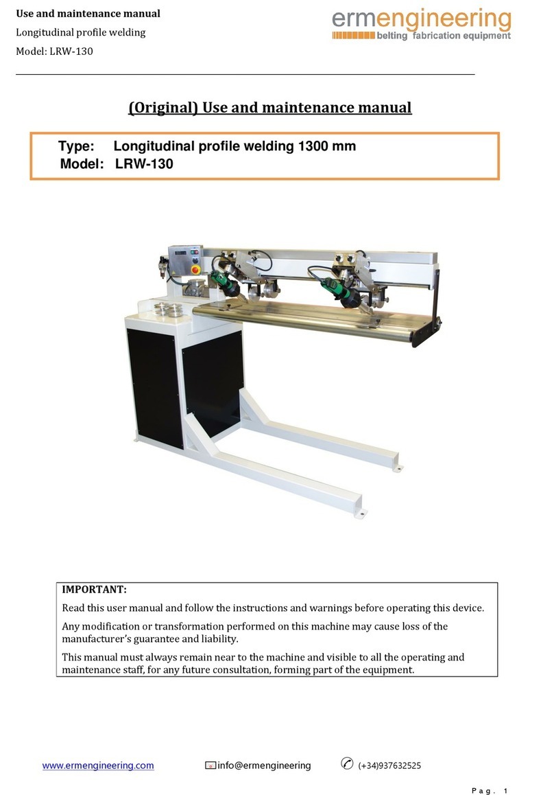
ermengineering LRW-130 Use and maintenance manual

schmersal
schmersal AZM201Z-I2-SK-T-1P2PW-DU Operation and assembly instructions
