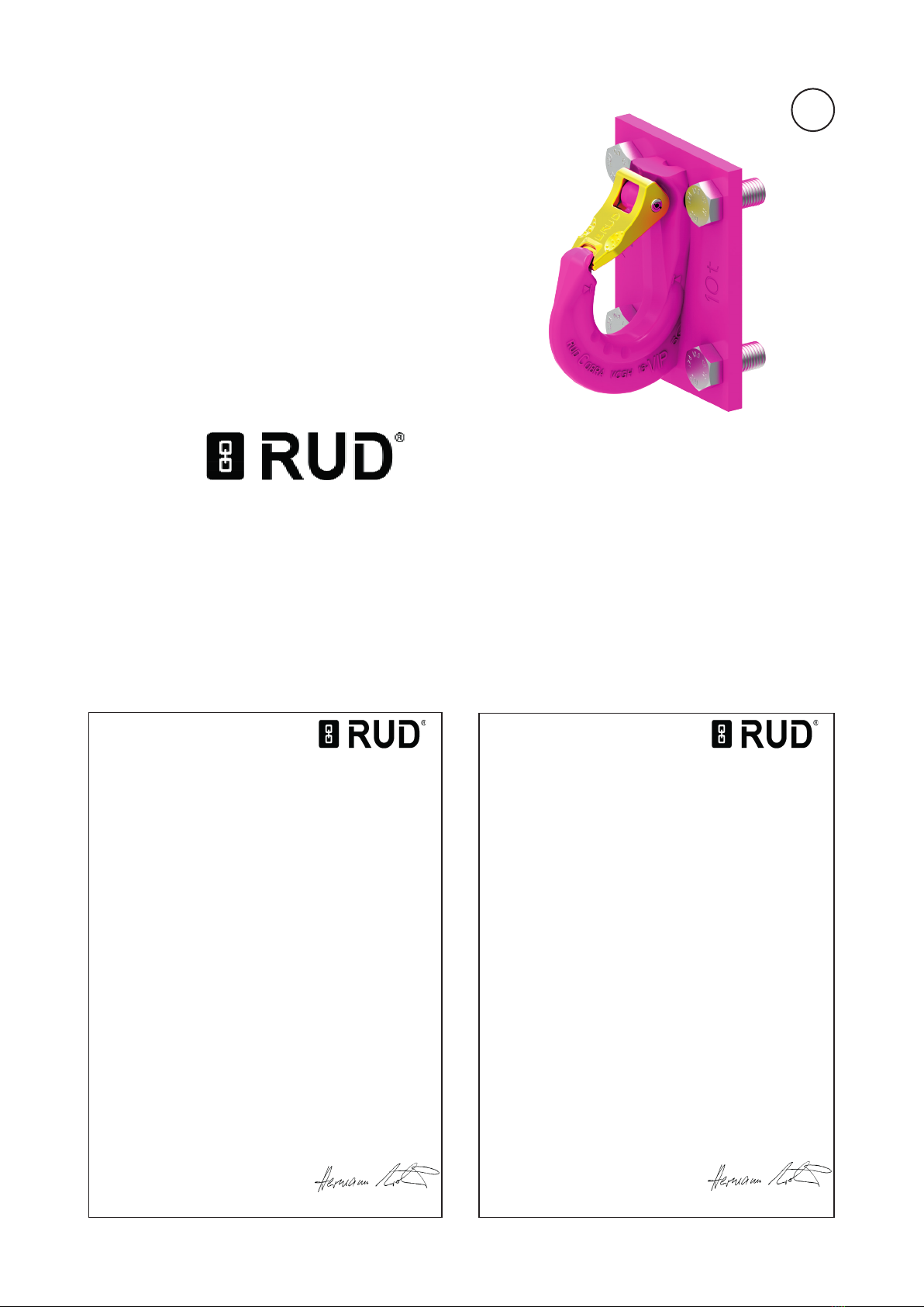
2VCGH-G
Carefully read the operating instructions
before using the lifting point VCGH-G.
Ensure that you have understood all the
contents.
Non-observation of the instructions can
lead to injuries or damage and will invali-
date the guarantee.
1 Safety instructions
WARNING
Incorrectly mounted or damaged lifting
points and improper use can lead to injuries
and damage to objects after a fall.
Check the lifting points carefully every time
before use.
• Withdraw all body parts (ngers, hands, arms etc.)
from the danger zone during the lifting process
(risk of crushing).
• The RUD lifting points VCGH-G may only be used
by authorised and instructed persons in compliance
with the DGUV Regulations 109-017 and in com-
pliance with any valid national regulations if used
outside Germany.
• Do not exceed the working load limit (WLL) indica-
ted on the lifting point.
• No technical modications must be made at the
VCGH-G.
• No persons are allowed in the danger zone.
• Standing below suspended loads is prohibited.
• Jerky lifting (strong impacts) should be prevented.
• Always ensure a stable position of the load when
lifting. Swinging must be prevented.
• Damaged or worn VCGH-G must not be used.
2 Intended use
• VCGH-G lifting points must only be attached at a
load or used at load accepting means.
• Their usage is intended to be used as lifting means.
• VCGH-G lifting points can also be used as lashing
points for xing lashing means.
• VCGH-G lifting points must only be used in the
here described operation purpose.
3 Assembly- and instruction manual
3.1 General information
• Eects of temperature:
Due to the DIN/EN bolts that are used in the
VCGH-G lifting points, the working load limit must
be reduced accordingly:
• -20°C up to 100°C no reduction (-20°F to 212°F)
• 100°C up to 200°C minus 15 % (212°F to 392°F)
• 200°C up to 250°C minus 20 % (392°F to 482°F)
• 250°C up to 350°C minus 25 % (482°F to 662°F)
Temperatures above 350°C (662°F) are not permitted!
• VCGH-G lifting points must not come into contact
with aggressive chemicals, acids and their vapours.
• The place where the VCGH-G lifting points are
xed should be clearly marked with colour.
• VCGH-G lifting points are supplied with crack test
inspected ICE-bolts.
• Original ICE-bolts are available as a spare part
from RUD.
• When using your own bolts, the bolts have to
be 100 % crack tested (a written conrmation
of the absence of cracks must be added to the
documentation). The min. quality of the hexagon
bolt had to be 10.9 accord. EN 24014 (DIN 931)
with the nominal diameter.
ATTENTION
A combination of bolts made of dierent
strength classes is not allowed to be used
for a xation of the excavator hooks.
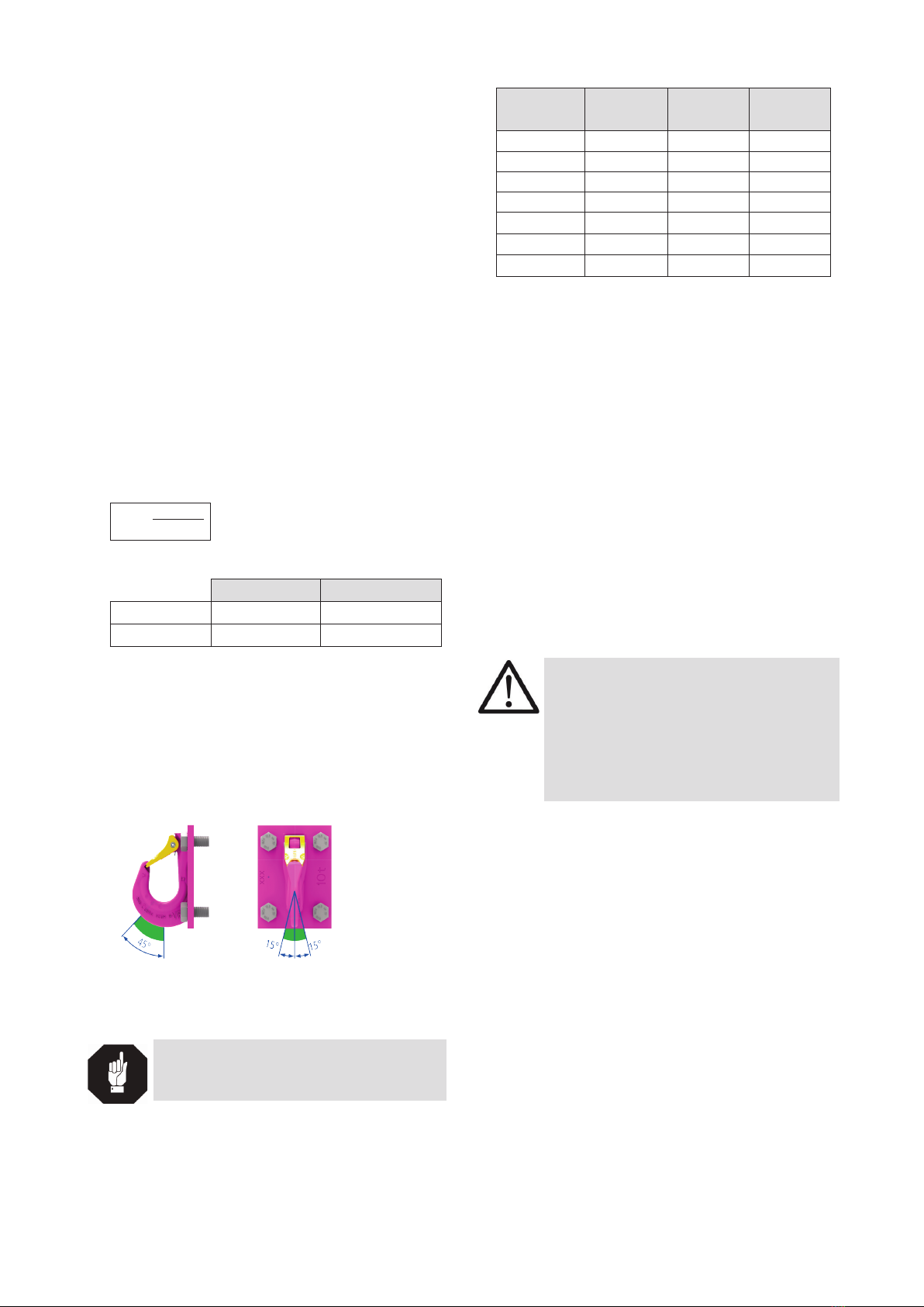
3.2 Hints for the assembly
Basically essential:
• The material construction to which the lifting point
will be attached, should be of adequate strength to
withstand forces during lifting without deformation.
The German testing authority BG/DGUV, recom-
mends the following minimum for bolt lengths:
• 1 x M in steel (minimum quality S235JR [1.0037])
• 1.25 x M in cast iron (for example GG 25)
• 2 x M in aluminium alloys
• 2.5 x M in light metals of low strength
(M = diameter of RUD lifting point bolt, for ex. M 20)
CONTENT
1 Safety instructions 2
2 Intended use 2
3 Assembly- and instruction manual 2
3.1 General information ..................................................2
3.2 Hints for the assembly ..............................................2
3.3 Hints for the usage ...................................................3
4 Inspection / Repair / Disposal 4
4.1 Hints for periodical inspections.................................4
4.2 Test criteria for the regular visual inspection by the
user...........................................................................4
4.3 Additional test criteria for the
competent person / repair worker.............................4
4.4 Disposal....................................................................4