Medora GridBee GF5000PW User manual
© 2019 Medora Corporation | www.medoraco.com | 866 - 437 - 8076 | [email protected]
O&M_GF5000PW_10307_20191010
GF5000PW Owner's Manual

Table of Contents
About Medora Corporation
Medora Corporation combines knowledge and experience from across the water quality spectrum to help
solve real-world problems. Whether in Lakes, Stormwater Retention Ponds, Raw Drinking-Source Reservoirs,
Water Treatment Plants, Potable Storage Tanks, or Wastewater Treatment Processes, Medora Corporation
equipment continues to be at the forefront as the #1 world leader for in-situ water body treatment.
© 2019 Medora Corporation | www.medoraco.com | 866 - 437 - 8076 | [email protected]
Table of Contents
10014_20191001
GF5000PW Owner's Manual
Safety
Operation
Site Preparation
Features
Assembly
Maintenance
Electrical
Technical Specifications
Troubleshooting
Parts Diagram
Dimension Drawing
Warranty
Customer Service
O&M_GF5000PW_10307_20191010

Carefully read safety information when you see
any safety symbols.
Be sure you have read all installation, operation, maintenance and safety instructions
before you install, service or begin to operate this unit.
Accidents occur every year because of careless use of industrial equipment. You can avoid
hazards by following these safety instructions, and applying some ordinary common sense
when operating or servicing this unit.
Keep in mind that full operator attention and alertness are required when operating or
servicing this unit.
USE COMMON SENSE!! Most accidents can be avoided by using common sense and
concentration on the job being done.
© 2019 Medora Corporation | www.medoraco.com | 866 - 437 - 8076 | [email protected]
Safety
Safety
1949_10036_20191001 O&M_GF5000PW_10307_20191010

IMPORTANT!!!
Follow all federal and state laws in regards
to safety regulations of working at heights,
conned spaces, rescue, etc. as required by
the U.S. Department of Labor, Occupational
Safety and Health Administration. Use
necessary PPE when placing and servicing
this unit.
Identify all possible hazards. Determine what
safeguards are needed and implement them.
Only you, the user, understand your product
and system characteristics fully. The ultimate
responsibility for safety is with you. Your
safety ultimately rests in your hands. Do
your part and you will enjoy safe, trouble free
operation for years to come. This instruction
manual is not intended to include a compre-
hensive listing of all details for all procedures
required for placement, operation and mainte-
nance. If you have a question about a proce-
dure or are uncertain about any detail, Do Not
Proceed. Please contact GridBee Customer
Service at 866-437-8076 to speak to a repre-
sentative.
ELECTRICAL HAZARD
WARNING: THIS EQUIPMENT CONTAINS HIGH
VOLTAGE! ELECTRICAL SHOCK CAN CAUSE
SERIOUS OR FATAL INJURY. ONLY QUALIFIED
PERSONNEL SHOULD ATTEMPT PLACEMENT,
OPERATION AND MAINTENANCE OF
ELECTRICAL EQUIPMENT. REMOVE ALL
SOURCES OF ELECTRICAL POWER BEFORE
PERFORMING ANY SERVICE WORK TO THE
MACHINE. USE PROPER LOCKOUT TAGOUT
(LOTO) PROCEDURES TO ENSURE A SAFE
WORK ENVIRONMENT.
Rotating Hazard
CAUTION: KEEP BODY APPENANDAGES OR
LOOSE CLOTHING AWAY FROM EQUIPMENT
WHILE OPERATING. ENSURE EQUIPMENT IS
OFF BEFORE ATTEMPTING SERVICE.
Crush Hazard
WARNING: DO NOT REMOVE ANY FLOAT
ASSEMBLY BOLTS OR PINS WHILE
EQUIPMENT IS FLOATING IN WATER.
EQUIPMENT MUST BE SECURELY
SUPPORTED BEFORE PERFORMING
SERVICE.
Laceration Hazard
CAUTION: EDGES MAY BE SHARP AND
CAUSE LACERATION IF PROPER CARE IS
NOT USED.
Entanglement Hazard
WARNING: ENSURE THAT PERSONNEL ARE
CLEAR OF THE ELECTRIC CORD AND CHAIN
TO AVOID ENTANGLEMENT.
Thin Ice Hazard
WARNING: ICE SURROUNDING MACHINE
MAY NOT SUPPORT WEIGHT, KEEP CLEAR OF
THIN ICE.
© 2019 Medora Corporation | www.medoraco.com | 866 - 437 - 8076 | [email protected]
Safety
Safety
1949_10036_20191001 O&M_GF5000PW_10307_20191010

Permit-Required
Conned Spaces
A conned space has limited openings for
entry or exit, is large enough for entering and
working, and is not designed for continuous
worker occupancy. Conned spaces include
underground reservoirs, ground storage tanks,
elevated tanks, silos, manholes, and pipelines.
Conned Space Tips
• Do not enter permit-required conned spaces
without being trained and without having a
permit to enter.
• Review, understand and follow employer’s
procedures before entering permit-required
conned spaces and know how and when
to exit.
• Before entry, identify any physical hazards.
• Before and during entry, test and monitor for
oxygen content, ammability, toxicity or
explosive hazards as necessary.
• Use fall protection, rescue, air monitoring,
ventilation, lighting and communication
equipment according to entry procedures.
• Maintain contact at all times with a trained
attendant either visually, via phone, or by
two-way radio. This monitoring system
enables the attendant and entry supervisor
to order you to evacuate and to alert
appropriately trained rescue personnel to
rescue entrants when needed.
Refer to 29 CFR 1910.146 for complete
regulations set by OSHA. Refer to your state's
regulations if your state established and operates
their own safety and health programs approved
by OSHA.
Protect Yourself
Medora Corporation insists that you comply with
all relative OSHA and local regulations while
installing and performing any maintenance to the
mixer circulation equipment.
Key OSHA Compliance Standards that must
be followed (and not limited to) are:
• 1910.146 Permit-required conned spaces
• 1910.147 Lockout/Tagout
• 1926.500 Fall Protection
Fall Protection Tips
• Identify all potential tripping and fall hazards
before work starts.
• Look for fall hazards such as unprotected
oor openings/edges, shafts, open hatches,
stairwells, and roof openings/edges.
• Inspect fall protection and rescue equipment
for defects before use.
• Select, wear, and use fall protection and
rescue equipment appropriate for the task.
• Secure and stabilize all ladders before
climbing.
• Never stand on the top rung/step of a ladder.
• Use handrails when you go up or down stairs.
• Practice good housekeeping. Keep cords,
welding leads and air hoses out of walkways
or adjacent work areas.
Refer to 29 CFR 1926.500 for complete
regulations set by OSHA. Refer to your state's
regulations if your state established and operates
their own safety and health programs approved by
OSHA.
Lockout Tagout
When the On/Off switch is in the "ON" position,
the mixer may start up at any time if not already
operating. The mixer's On/Off switch can be
locked out by placing a pad lock thru the door latch
of the controller after the switch has been turned
to the "OFF" position. The On/Off switch is to be
used as the emergency stop.
© 2019 Medora Corporation | www.medoraco.com | 866 - 437 - 8076 | [email protected]
Safety
Safety
1949_10036_20191001 O&M_GF5000PW_10307_20191010

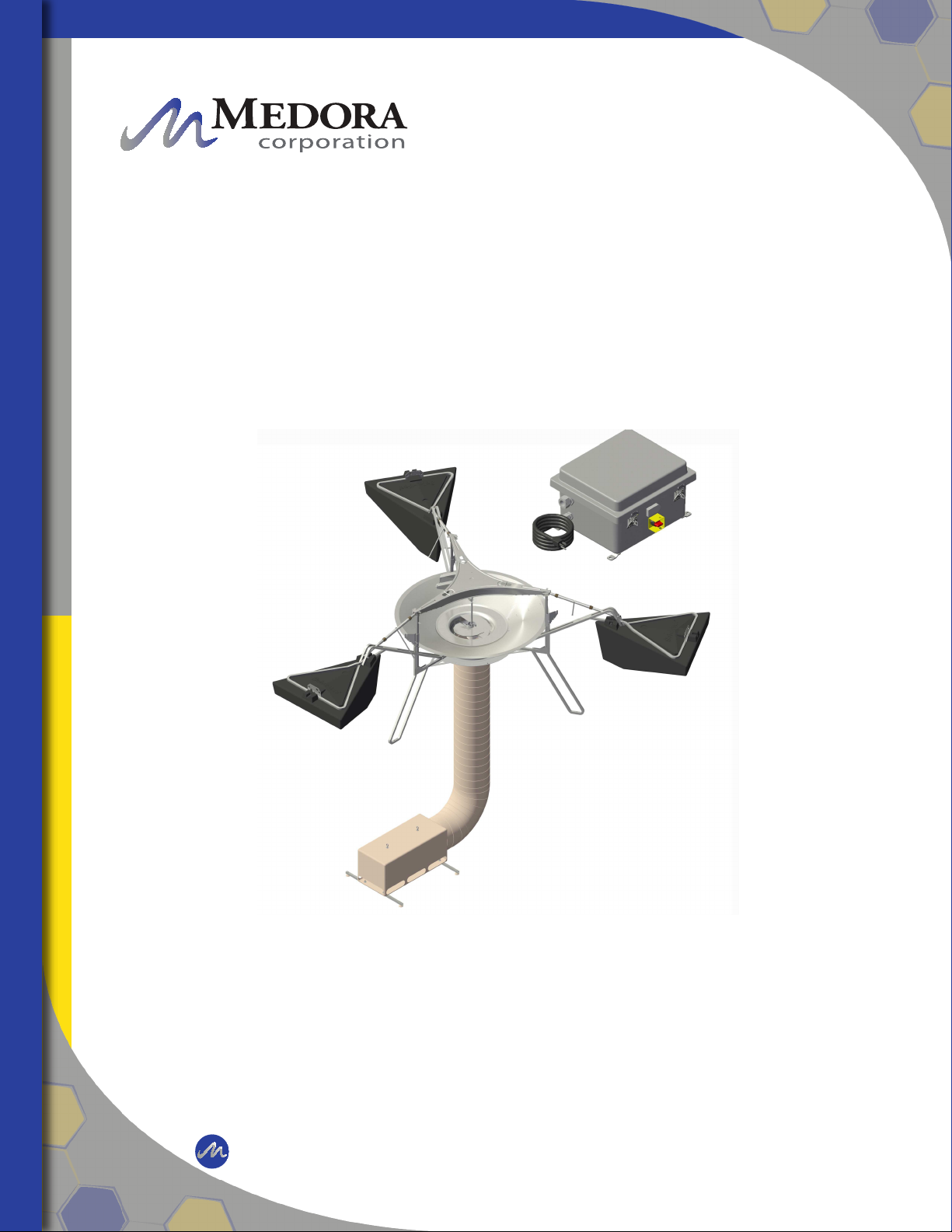
The GridBee is designed to circulate water by
bringing water from below and sending it out
across the top in a thin layer causing a mixing
effect. The laminar layer ows outward radially, in
diverging “stream lines” from the distribution dish.
As it does, vertical ow is induced in between the
water being drawn below and the water above. At
the level of the ow intake, water is drawn from
all corners of the pond. As this lower layer of uid
makes its way inward with converging streamlines
to the GridBee, the water is forced upward, toward
the surface, providing gentle mixing,
de-stratication, and surface renewal.
The GF series GridBee requires a minimal amount
of AC grid-power. The grid provides power
to the onboard AC:DC power box and motor
controller that drive the brushless motor. The GF
Technology allows the GridBee to operate during
day and night while drawing minimal amount of
power from the grid.
During operation, a visible ow can be observed
coming off the distribution dish and spreading
outward. The motor and impeller is designed to
operate at the same full speed as the
solar-powered SolarBee models.
GridBee Flow Pattern
Flow Coming Off Distribution Dish
© 2019 Medora Corporation | www.medoraco.com | 866 - 437 - 8076 | [email protected]
Operation
Operation
GF Series
10181_20191007 O&M_GF5000PW_10307_20191010

Properly planning out the job site before proceeding is very important to peforming an efcient and
successful potable water equipment installation. Every potable water tank and reservoir is unique
and therefore the following are general guidelines and considerations that will need to be evaluated
for each specic site.
HATCH REQUIREMENTS
Hatches with a clear opening of at least 6 feet
X 6 feet (1.83 m X 1.83 m) will allow the core
unit assembly to be installed without major
disassembly required.
For smaller hatches, a clear, unobstructed
opening of at least 3 feet X 3 feet (0.92m X
0.92m) is required to t the machine components
through when broken down into its smallest
possible size.
WET OR DRY INSTALLATION
A decision will be required to either install the
machine while the reservoir is empty or lled with
water.
Wet installations are generally preferred when the
units are installed by our factory installers to allow
for proper nal adjustments and settings during
startup which directly follows installation. Our
factory installation teams have extensive training
and many installation tools to assist in a wet
installation.
If proper equipment and safety training are not
available, a wet installation may not even be
possible, and therefore a dry installation may be
required and startup will have to follow at a later
time once the reservoir is lled with water.
SANITARY REQUIREMENTS
For potable water equipment installations, it is
very important to maintain sanitary conditions by
properly disinfecting all equipment and personnel
that come into contact with the reservoir interior
and potable water. It is recommended that once
the hatch is chosen for equipment and personnell
entry, a clean zone be designated around the
hatch. The clean zone establishes a boundary
where anything that comes in contact with that
zone, shall be sanitary and adequately disinfected,
allowing it to pass through the clean zone and
into the reservoir. Standard practice in the United
States is to use a 200 part per million sodium
hypochlorite in water solution as a disinfectant to
all equipment and personnell clothing/footwear
coming into contact with the reservoir interior and
potable water.
SAFETY
Prior to commencing installation and nalizing on
the installation work areas, the jobsite should be
evaluated for all safety hazards including, but not
limited to: Conned Space Entry, Fall Protection,
Working Over Water, Overhead Equipment,
Communicatoin Barriers, Equipment Handling, etc.
Once safety hazards are identied, hazard
mitigation measures should be taken and
safety training procedures must be practiced to
accomplish the installation without incident.
© 2019 Medora Corporation | www.medoraco.com | 866 - 437 - 8076 | [email protected]
Install Site Preparation
Install Site Preparation
10153_20191007 O&M_GF5000PW_10307_20191010
The GridBee utilizes high efcient brushless motor technology which enhance its performance through more
efcient and durable components, as well as easy component access, and a more robust frame structure.
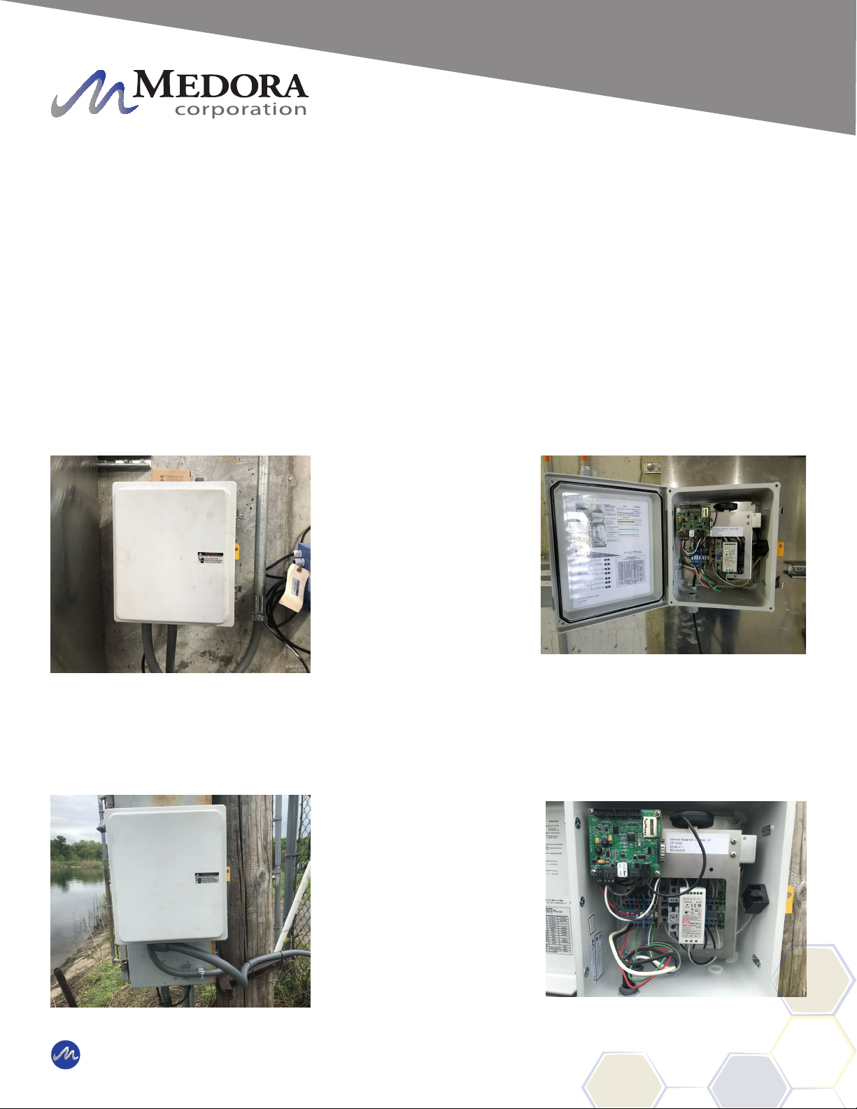
Electronics
Electrical Control Box - The electrical control box is located on the exterior of the tank / reservoir. The
electrical control box converts 110VAC power to a clean 45VDC power source which then operates the motor
controller. The control box also consists of a ground fault interupter (GFI) switch to aid in protection of faulty
circuits or shorting of circuits. A durable 316SS Cord Grip is used to handle all weather elements, protecting
the penetration of the electrical cable to the motor controller on the inside of the tank.
Electronic Control Box in
Tank Reservoir
Electronic Control Box of a
Service Reservoir
© 2019 Medora Corporation | www.medoraco.com | 866 - 437 - 8076 | [email protected]
Features
Features
GF Large Frame Series
10308_20191007 O&M_GF5000PW_10307_20191010
SCADA outputs offering machine operation parameters
reside within the digital controller. Please contact
Medora Corporation if you are interested in receiving
these parameters.
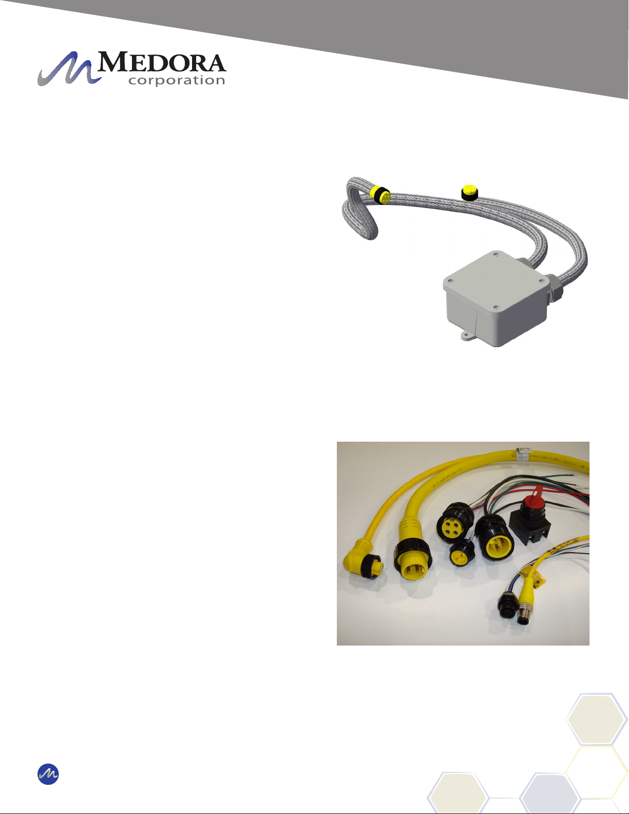
Motor Controller - The motor controller is located near
the motor just below the top plate of the Machine. The
motor controller is sealed in line with the electrical cord
that runs to the brushless motor.
The motor controller on the Machine receives power
and signals from the main control center located inside
the external enlosure. These signals are used to
operate the brushless motor at the commanded speed.
The motor controller also sends feedback signals back
up to the main control center.
Due to the high frequency of communication between
the motor controller and brushless motor, the two
components need to be located close to one another.
This is the primary reason for having the motor
controller located directly on the Machine.
All electronic connections on the Machine equipment
should only be used for the inputs or outputs that they
are labeled and designed for. If any of the leads going
into the electronic controller are disconnected, be
sure when re-connecting to place them in the proper
position.
Wiring - All electric wiring includes corrosion-resistant,
industrial cords with molded, weather and watertight
connectors. The connectors are indexed to prevent
improper wiring. A general electrical schematic can
be found in the Maintenance and Field Adjustment
section.
Motor Control Cord
Durable Wiring And Connectors
© 2019 Medora Corporation | www.medoraco.com | 866 - 437 - 8076 | [email protected]
Features
Features
SB / GF PW Series Large Frame Mixers
10165_20191008 O&M_GF5000PW_10307_20191010

Brushless Motor / Impeller
Brushless Motor - The brushless motor is located
directly below the Top Deck. 4 bolts run down through
the Top Deck and into the housing of the brushless
motor fastening it onto the machine.
The brushless motor is built to be very durable. The
housing is constructed of casted aluminum. The
brushless motor runs very quietly and smoothly. It
does not require any maintenance. A drive shaft
extends through the bottom center of the housing.
CAUTION: THE BRUSHLESS MOTOR WEIGHS
APPROXIMATELY 80 LBS (36KG). DO NOT
REMOVE WITHOUT DISCUSSING THE
PROCEDURES AND EQUIPMENT NECESSARY
WITH A MEDORA CORPORATION SERVICE TEAM
MEMBER.
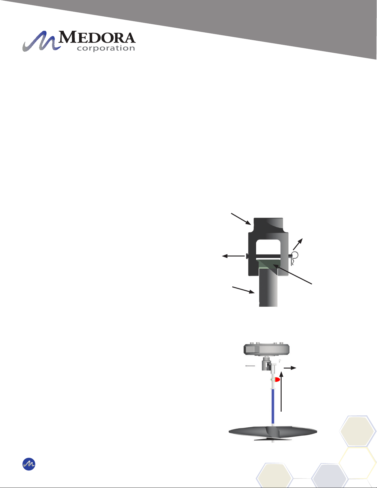
Shaft Coupling - The shaft coupling connects the
brushless motor drive shaft to the impeller shaft. The
shaft coupling is located directly below the brushless
motor and is made up of 3 main components. These
components are called the upper coupling, lower
coupling, and coupling sleeve. The shaft coupling is
designed to allow quick disconnect for removal of the
impeller assembly. Disconnecting the impeller shaft
from the brushless motor shaft is simply accomplished
by pulling out a pin and requires no tools. The upper
coupling remains attached to the brushless motor while
the lower coupling and coupling sleeve remain on the
impeller shaft.
Brushless Motor
Upper Coupling
Lower Coupling
Coupling Sleeve
Clevis Pin
© 2019 Medora Corporation | www.medoraco.com | 866 - 437 - 8076 | [email protected]
Features
Features
SB / GF PW Series Large Frame Mixers
10165_20191008 O&M_GF5000PW_10307_20191010

Impeller Assembly - The impeller assembly is made
up of the stainless steel impeller shaft, stainless steel
ag indicator, freeze sleeve, stainless steel impeller
blades, and plastic impeller bushing. The impeller
assembly is easily removed by pulling a pin on the
shaft coupling.
CAUTION: KEEP BODY APPENDAGES OR
LOOSE CLOTHING AWAY FROM THE IMPELLER
ASSEMBLY WHILE THE MACHINE IS OPERATING!
IF MAINTENANCE IS REQUIRED, BE SURE TO
TURN THE MACHINE OFF FIRST!
The ag indicator is xed to the shaft and used as a
visual indicator of the impeller shaft's rotational speed.
An food grade oil-lled, Teon freeze sleeve secured
with o-rings surronds the impeller shaft. The freeze
sleeve is free to rotate on the shaft. If the water should
freeze around the machine, the freeze sleeve will stand
still, frozen in by the ice, but inside the plastic sleeve,
the impeller shaft will be turning.
The impeller blades are welded to a hub that is
securely fastened to the impeller shaft. The impeller
is designed to gently pump water from below and can
handle up to 4-inch (10cm) spherical solids.
The impeller bushing is a smooth collar that the
impeller shaft tip ts into. The impeller bushing aligns
and centers the impeller shaft within the machine.
Turn Machine Off Before
Performing Maintenance
CAUTION
Moving blade.
Rotating parts and shaft can
cause injury.
Keep hands clear while
machine is operating.
Flag
Indicator
Impeller Blades
Impeller Hub
Freeze Sleeve
Impeller
Bushing
Block
Impeller Assembly
© 2019 Medora Corporation | www.medoraco.com | 866 - 437 - 8076 | [email protected]
Features
Features
SB / GF PW Series Large Frame Mixers
10165_20191008 O&M_GF5000PW_10307_20191010
MODEL MAY VARY
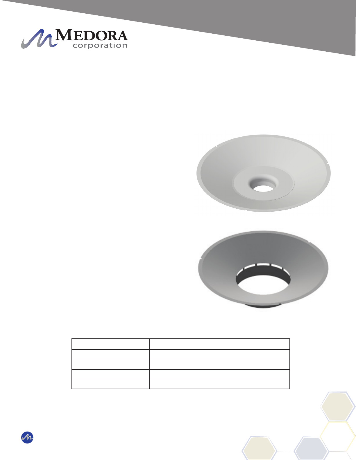
Distributor Dish
The distributor dish, structural members, structural
fasteners, and mounting brackets are constructed
of stainless steel.
Distributor Dish - Near-laminar ow is achieved
by the Machine due to its uniquely designed
distributor dish. The impeller rotates while sitting
within the lower half of the distributor dish. There
are also small water passages located below the
dish to strengthen the induced ow effect (water
movement occuring between the lower water layer
entering the machine and the upper water layer
leaving the dish).
The top lip of the distributor dish is set from 3/4
inch to 2.5 inches (2 cm to 6.4 cm) (Please refer
to the table below for exact settings) below the
surface of the water to achieve best ow results.
The distributor dish depth is set by rotating the
turnbuckles located on the oat arms.
Distributor Dish
Machine Model Water Level
2500 3/4 in to 1 in (2 cm to 2.5 cm)
5000 1 in to 1 1/2 in (2.5 cm to 3.8 cm)
7500 2 in to 2 1/2 in (5.1 cm to 6.4 cm)
10000 2 in to 2 1/2 in (5.1 cm to 6.4 cm)
© 2019 Medora Corporation | www.medoraco.com | 866 - 437 - 8076 | [email protected]
Features
Features
SB / GF PW Series Large Frame Mixers
10165_20191008 O&M_GF5000PW_10307_20191010
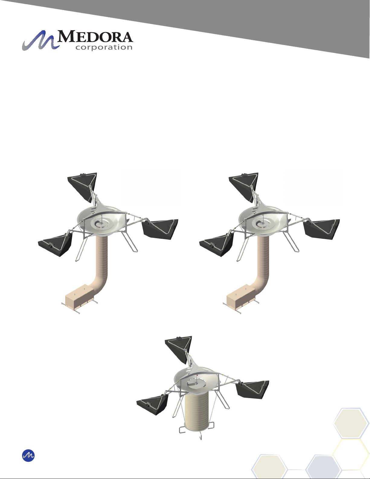
Hose / Intake - The hose extends from below the dish down to the intake. The intake is generally set just
above the oor of the reservoir. As the water level uctuates, the intake remains at a xed level above the
reservoir bottom as the extra hose lays on the bottom. The intake draws water horizontally into the hose.
The contact between the intake and the oor prevents the machine from rotating or moving out of place. The
machine naturally has a very small torque due to impeller rotation.
SB2500PW
Hose and Intake Box Conguration - MODEL MAY VARY
SB5000PW - GF5000PW
SB10000PW - GF10000PW
© 2019 Medora Corporation | www.medoraco.com | 866 - 437 - 8076 | [email protected]
Features
Features
SB / GF PW Series Large Frame Mixers
10165_20191008 O&M_GF5000PW_10307_20191010
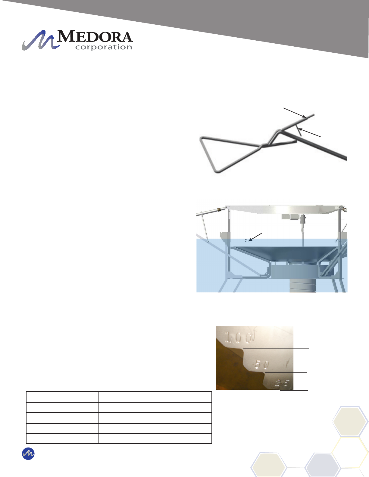
Float Arms / Floats
The Machine contains 3 oat arms and 3 oats. The oat
arms allow vertical positioning of the machine and the
oats provide buoyancy.
Float Arms - The oat arms are constructed of stainless
steel components. They connect the oats to the
central machine structure. Each oat arm has a sturdy
turnbuckle. The turnbuckles can easily be rotated
to adjust the vertical height of the distributor dish.
Lengthening the turnbuckle (rotating clockwise) will raise
the lip of the distributor dish, whereas shortening the
turnbuckle (rotating counter-clockwise) will cause the lip
of the distributor dish to lower.
The turnbuckle and oat arm structure components are
constructed with robust stainless steel materials allowing
the Machine to operate in severe environments without
being damaged. The turnbuckle is self locking. Simply
rotate the handle to expand or collapse the turnbuckle for
dish depth adjustment.
It is important to check the distributor dish depth routinely.
The Machine naturally drops into the water over time
due to biomass buildup and trapped air escaping from
the hose. If the distributor dish lip is too high, the water
coming off the lip may become turbulent and the ow rate
of the machine may be reduced.
Turnbuckle
Float Arm
Handle
(Refer to table below)
Distance Between Distributor
Dish And Water Level
Dish Depths For Different Models
10000
7500
5000
2500
WATER LEVEL NOTCH SETTING FOR:
Machine Model Water Level
2500 3/4 in to 1 in (2 cm to 2.5 cm)
5000 1 in to 1 1/2 in (2.5 cm to 3.8 cm)
7500 2 in to 2 1/2 in (5.1 cm to 6.4 cm)
10000 2 in to 2 1/2 in (5.1 cm to 6.4 cm)
© 2019 Medora Corporation | www.medoraco.com | 866 - 437 - 8076 | [email protected]
Features
Features
SB / GF PW Series Large Frame Mixers
10165_20191008 O&M_GF5000PW_10307_20191010

If the distributor dish lip is too low, the water coming
off the lip will ow just underneath the surface of the
pond and the surface will not be renewed.
Each oat arm is connected to the central machine
structure with 1 bolt and 1 pin. Each oat is
connected to the oat arm by 2 pins. The turnbuckle
can be removed from the oat arm by pulling a pin,
but should only be done when the unit is resting on
the shore.
If re-attaching the turnbuckle to the oat arm, be sure
that each threaded end of the turnbuckle together are
screwed all the way in or all the way out before re-
attaching. If threaded ends are not equally expanded
or collapsed before xing the ends, the turnbuckle will
have limited adjustment.
Floats - The Machine has 3 oats, made from high
density Polyethylene. The oats are lled with a
Polystyrene closed-cell foam for long term buoyancy.
The oats have a uniquely designed shape to:
• Minimize the interference with the water
ow on the surface coming off the distributor
dish.
• Have a low prole above the water for
minimizing wind resistance and offering less
exposure to vandalism.
• Avoid being crushed by ice pressure.
• Provide extra buoyancy when needed without
going much deeper into the water.
Float Arm Connection Points
Pin
Pin
Pin
Pin
Float
CAUTION: DO NOT REMOVE
ANY FLOAT ASSEMBLY PINS OR
BOLTS WHILE THE MACHINE IS
FLOATING IN THE WATER! THE
MACHINE MUST BE RESTING
ON THE GROUND OR SAFELY
SUPPORTED TO RELIEVE
THE FORCES ON THE FLOAT
ASSEMBLY STRUCTURES PRIOR
TO DISASSEMBLY! FAILURE
TO FOLLOW THIS WARNING
COULD LEAD TO SINKING THE
MACHINE OR SERIOUS INJURY!
© 2019 Medora Corporation | www.medoraco.com | 866 - 437 - 8076 | [email protected]
Features
Features
SB / GF PW Series Large Frame Mixers
10165_20191008 O&M_GF5000PW_10307_20191010
Core Unit Disassembly
TOOLS REQUIRED:
13mm Wrench
13mm Socket Wrench
19mm Wrench
19mm Socket Wrench
Impeller Removal
During most potable reservoir installations, it
is recommended that the impeller be removed
if the equipment is passing through a small
hatch and will be orientated sideways or
disassembled.
STEP 1: First identify the impeller assembly
components shown to the right.
STEP 2: With SolarBee machine off, locate
the clevis pin going through the upper shaft
coupling. Remove the hair pin and pull clevis
pin out.
STEP 3: Grab the impeller shaft below the
ag indicator, lift up and then outward until
lower coupling and shaft are disconnected
from upper coupling and brushless motor.
STEP 4: Place the Impeller Assembly off to
the side and re-insert the Clevis Pin and Hair
Pin into the Upper Coupling for safe keeping.
• • • IMPORTANT • • •
The following pages give detailed instructions on how to assemble different portions of the machine,
however, the order in which the components are assembled may need to be altered based on
the hatch size and whether the reservoir will be dry or empty. For instance, the hose and intake
assembly can be performed on the tank exterior prior to lowering the equipment inside if the hatch
size is at least 6 feet X 6 feet (1.83 m X 1.83 m) which will allow the core unit assembly to be installed
without major disassembly required. For smaller hatches, the core unit will need to be broken down
into 3 primary components and the hose and intake assembly will need to be performed inside
the reservoir. The following order listed is based on a dry installation and small hatch opening.
Coupling Sleeve
Lower Coupling
Upper Coupling
Hair Pin
Clevis Pin
Impeller Assembly Removal Motion
Shaft Coupling
© 2019 Medora Corporation | www.medoraco.com | 866 - 437 - 8076 | [email protected]
Equipment Assembly
458_10264_20191008 O&M_GF5000PW_10307_20191010
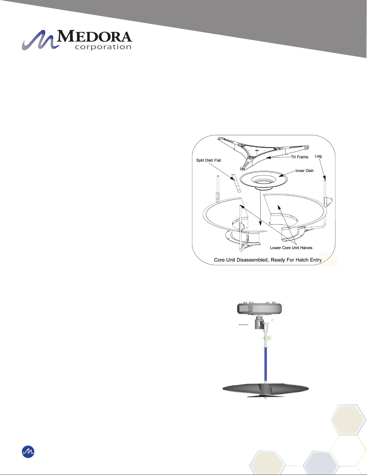
Core Unit Disassembly (Cont.)
STEP 1: First identify the Core Unit Assembly
Components shown to the right.
STEP 2: Remove the three M12 Bolts holding
the Tri-Frame to the Lower Core Unit Legs
and remove the Tri-Frame from the Core Unit
by lifting upward.
STEP 3: On the same half of the Split Dish,
remove four of the M8 Bolts for each Split
Dish Flat to separate the Lower Core Unit into
two halves. The Split Dish Flats can remain
connected to one half as long as the hatch
opening is large enough.
STEP 4: The Core Unit Assembly is now
broken down into it's smallest form and each
component will t through a hatch with clear,
unobstructed opening of at least 3 feet X 3
feet (0.92m X 0.92m).
STEP 5: Once these components are lowered
through the hatch, they can be reassembled
using the opposite order of STEPS 1-4.
Impeller Reinsertion
STEP 1: Place impeller assembly back
in place (Slide lower coupling into upper
coupling and allow to drop down into place).
Be sure bottom of impeller shaft ts into the
bushing in the dish and that the coupling
sleeve is in place inside the shaft coupling
assembly.
STEP 2: Place clevis pin back through upper
shaft coupling and secure with hair pin.
Impeller Assembly Reinsertion Motion
© 2019 Medora Corporation | www.medoraco.com | 866 - 437 - 8076 | [email protected]
Equipment Assembly
458_10264_20191008 O&M_GF5000PW_10307_20191010

Float Assembly
NO TOOLS REQUIRED
STEP 1: Locate one oat, one oat arm, one
oat bracket, and 2 oat pin sets. Observe
that there are two slots on the top of the oat
which t around the oat arm. One slot runs
left and right, the other runs front to back. If
oat pins are in the slots, remove them.
STEP 2: Orientate the oat so that it will t
around the oat arm when the oat is raised
into place.
STEP 3: Place the oat plate into oat slot 1
furthest from the core unit assembly aligning
the holes of the oat slot with the small holes
on the oat plate (see photo).
STEP 4: Once the oat plate is in place on
the oat, raise the oat up tting it into the oat
arm. Use the oat pins to secure the oat to
the oat arm.
STEP 5: Place hairpins in each oat pin to
secure it and prevent the pin from coming out.
STEP 6: Repeat Steps 1 through 5 for the
other two oats.
NOTE: The oat plate may not be used on one
of the three oats.
After familiarizing yourself with all the components and gathering the necessary tools, you are ready
for setting up the SolarBee unit. Find a location where you have approximately 20 ft of working
space near the reservoir that the SolarBee will be put in (The less distance you have to move the fully
assembled machine, the better). Follow these steps to prepare the SolarBee before oating it in the
water:
© 2019 Medora Corporation | www.medoraco.com | 866 - 437 - 8076 | [email protected]
Equipment Assembly
458_10264_20191008 O&M_GF5000PW_10307_20191010
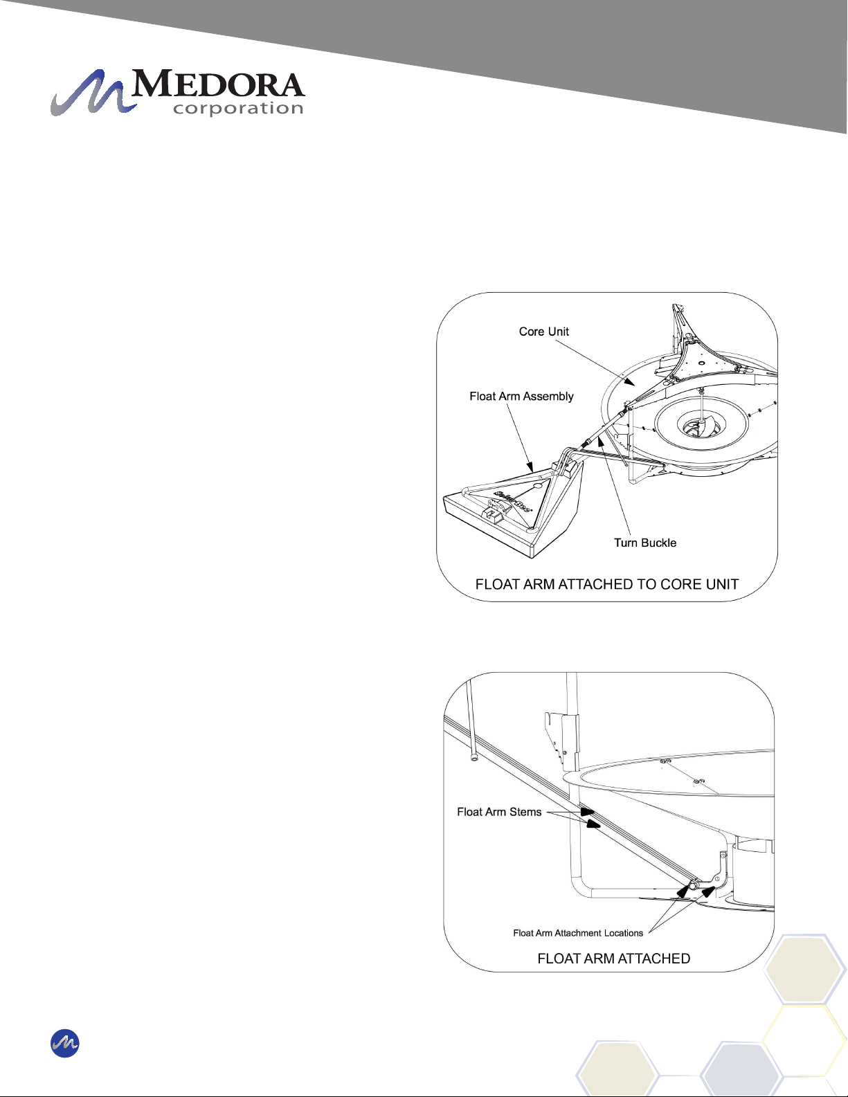
Float Arm Assembly
TOOLS REQUIRED:
(2) 19mm wrench
19mm socket wrench (optional)
STEP 1: Reference the previous page to
select which oat arm connection hole is
required for your machine.
IMPORTANT: Be sure to use the proper hole
to avoid a prolonged installation.
STEP 2: Locate the 3 oat arm assemblies.
Have the M12 x 90mm long bolts and M12
nylok nuts easily accessible near the core unit
assembly.
STEP 3: Take the oat arm and slip the
narrow end with Float Arm Stems around the
core unit leg. Align the holes through the
Float Arm Stems with the correct oat arm
connection hole determined from Step 1.
STEP 4: Once aligned slide the M12 X 90mm
bolt through all holes. Tighten a M12 nylok nut
onto the bolt until there is little play or space
between the bolted components. Use a two
19mm wrenches to tighten nut.
STEP 5: Repeat steps 2 and 3 for the other 2
oat arms.
© 2019 Medora Corporation | www.medoraco.com | 866 - 437 - 8076 | [email protected]
Equipment Assembly
458_10264_20191008 O&M_GF5000PW_10307_20191010
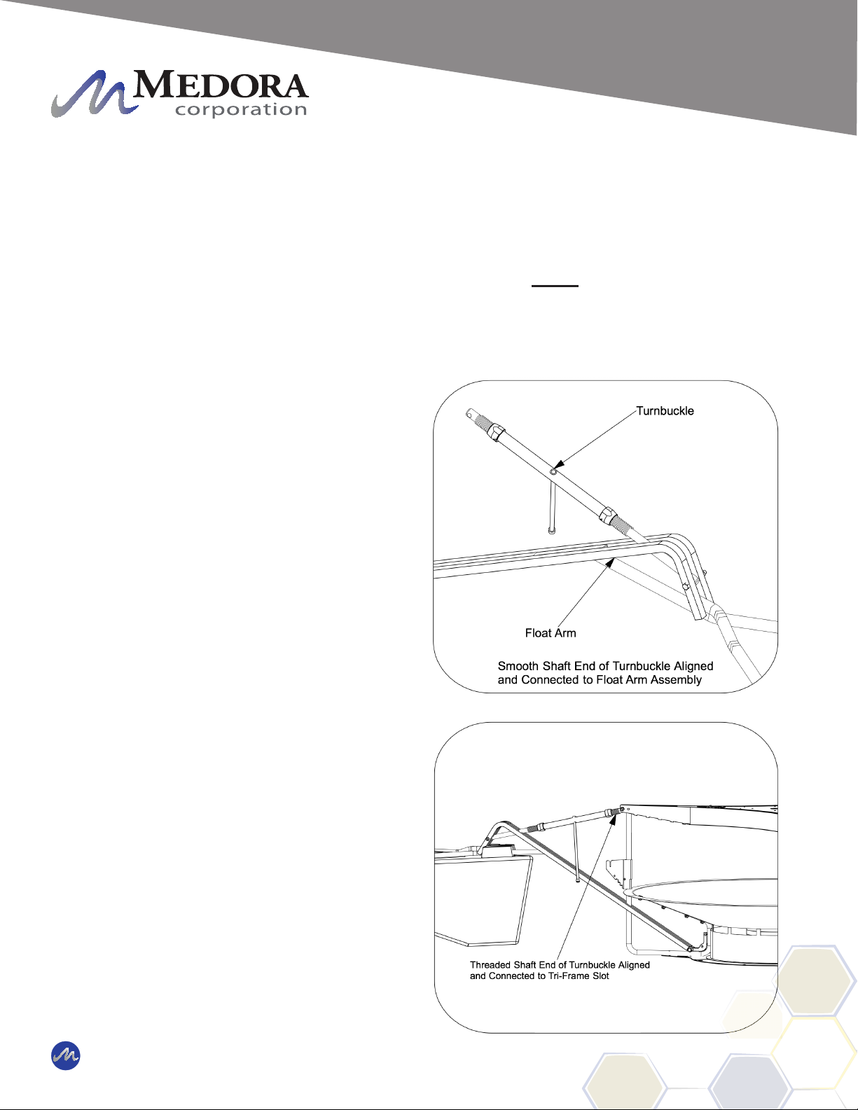
Turnbuckle Assembly
NO TOOLS REQUIRED:
STEP 1: Locate the three turnbuckles, M12
90mm Bolts, M12 55mm Bolts, and Nylok
Nuts.
STEP 2: Notice that the turnbuckle assembly
has an end with a smooth shaft and the other
end with threaded shaft.
STEP 3: Take the threaded shaft end of
the turnbuckle assembly and slip it into the
Triframe of the core unit assembly. Align
the holes and slide the M12 55mm Bolt into
position and tighten the Nylok nut.
STEP 4: Once the upper part of the
turnbuckle assembly is in place, take the
opposite end of the turnbuckle and slide it into
the oat arm assembly as shown in picture.
STEP 5: Align the hole through the shaft with
the oat arm assembly holes and slide the
M12 90mm Bolt and tighten the Nylok nut.
STEP 6: Repeat steps 2 through 5 for each
turnbuckle assembly.
• • • IMPORTANT • • •
Hold the center of the turnbuckle assembly and turn both ends all the way into the
center. Skipping this step will cause decreased extension of turnbuckle and more
time to install may be required.
© 2019 Medora Corporation | www.medoraco.com | 866 - 437 - 8076 | [email protected]
Equipment Assembly
458_10264_20191008 O&M_GF5000PW_10307_20191010
Table of contents
Popular Industrial Equipment manuals by other brands


Team
Team SILK AX14-60 instruction manual

Kidde
Kidde K-R Series Installation and operation guide

UNITED Fire Systems
UNITED Fire Systems STANDPIPE-PAC SSS-101 Design, Installation, Operation, and Maintenance Manual

Georg Fischer
Georg Fischer Signet 2630-X instructions

Dynapac
Dynapac F1000T operation & maintenance

Fein
Fein RS17-70E Series manual

schmersal
schmersal AZM201B-ST2-T-1P2PW Instructions for operation

SCHUNK
SCHUNK SRM 10 Assembly and operating manual

SMC Networks
SMC Networks MAX 700 Service and maintenance notes

Veit Brisay
Veit Brisay Fuse Master BX Series Handbook

MVP
MVP HVLS-1000 Operation manual

Magnum Industrial
Magnum Industrial MI-31662 operating manual