Tractel Greifzug blocstop BSO Series User manual
Fall arrest device for suspended material-lifting and rigging installations
Fangvorrichtung für hochziehbare Personen- und Materialaufnahmemittel (PAM & MAM)
Dispositif antichute pour plateformes suspendues pour levage de personnens et matériel (PSLP & PSLM)
Opvangvoorziening voor omhoog trekbare personen- en materiaalhefmiddelen (PAM & MAM)
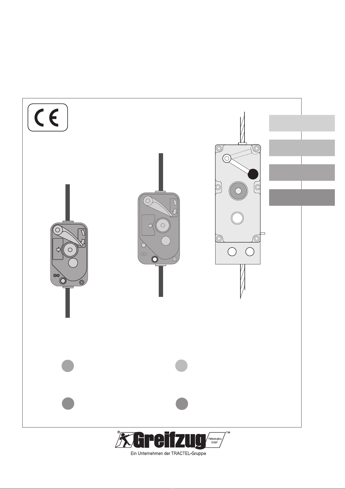
blocstop™BSO
blocstop™ BSO
2050/2360
blocstop™ BSO
1000
blocstop™ BSO
500
STOP
AUF
STOP
AUF
English
Deutsch
Français
Übersetzung der
Original-Montage- und
Bedienungsanleitung
D
Original Operation and
Installation Manual
GB Traduction du manuel
d´installation et de
manutention original
FR
G 905.4 (blocstop_bso).indd
Nederlands
Vertaling van de originele
montage- en bedienings-
handleiding
NL
2 / 48 Rev. 01/2010-EN-DE-FR-NL
EN
blocstopTM BSO
FR
DE
NL
Components/Bestandteile/Composants/Bestanddelen
Type
Typ
Type
Type
Capacity in t
Tragfähigkeit in t
Capacité in t
Draagvermogen in t
Wire rope specification
Seilspezifikation
Spécification du câble
Kabelspecificatie
Bolt-Ø in mm*
Bolzen-Ø in mm*
Diamètre des axes*
Bout-Ø in mm*
Persons
Personen
Personnes
Personen
Material
Material
Materiel
Materiaal
Ø in mm
Ø in mm
Ø du câble en mm
Ø in mm
Minimum tensile strength in kN
Mindestbruchkraft in kN
Force minimal de rupture en kN
Minimum breukkracht in kN
BSO 510 — 0,35 6 28,5 12
BSO 500 0,5 0,5 8 55,0
BSO 520 0,5 0,5 9 63,8
BSO 1000 0,5 0,5 8 55,0
BSO 1020 0,8 0,8 9 63,8
BSO 1030 1,0 1,0 10 83,0
BSO 1040 1,0 1,0 11,5 90,2
BSO 2050 2,0 2,6 14 157,1 22
BSO 2360 2,3 3,0 16 180,5
Table/Tabelle/Tableau/Tabel 1
Technical Data/Technische Daten/Données techniques/Technische gegevens
BSO 2050–2360
BSO 500–520
BSO 1000–1040
* Minimum strength
of bolt material: 800 N/mm
2
≅800 MPa
* Mindestfestigkeit des
Bolzenwerkstoffes: 800 N/mm
2
≅800 MPa
*
Qualité min.:
classe 8.8
800 N/mm
2
≅800 MPa
* Min. sterkte van
het boutenmateriaal: 800 N/mm
2
≅800 MPa
Fig./Abb./Fig./Afb. 2
1
6
4
3
5
7
2
Fig./Abb./Fig./Afb. 1
BSO 510–2360 for speeds up to: 18 m/min
BSO 510–2360 für Geschwindigkeit bis: 18 m/min
BSO 510–2360 pour vitesses jusqu´à: 18 m/min
BSO 510–2360 voor snelheid tot: 18 m/min

3 / 60
EN
Rev. 01/2010-EN
Operation and Installation Manual blocstop TM BSO
11. Operating / Working ..................................11
11.1 Checking before starting work...........11
11.2 Working with a PAM ..........................11
11.3 Working with a MAM .........................11
11.4 Manual EMERGENCY-STOP.............12
12. Measures to be taken immediately
after an emergency-stop...........................12
12.1 Measures to be taken when
using a PAM ......................................12
12.2 Measures to be taken when
using a MAM .....................................12
12.3 Measures to be taken after a
problem or an emergency-stop .........12
13. Predictable misuse....................................13
14. Dismantling................................................13
15. Transport and storage ..............................13
16. Maintenance ..............................................13
16.1 Authorised maintenance personnel ...13
16.2 Inspection requirements ....................13
16.3 Care and maintenance ......................14
17. Disposal and environmental protection...15
18. Troubleshooting ........................................15
Contents
1. General information ....................................4
1.1 Terms and abbreviations used in this
manual ................................................4
1.2 Symbols used in this manual...............5
2. Safety ...........................................................5
2.1 General safety instructions..................5
2.2 Instructions for the operator ................6
2.3 System manufacturer’s
responsibilities.....................................6
3. Overview ......................................................6
3.1 Delivery state ......................................6
3.2 Package contents ................................6
3.3 Equipment description.........................6
4. Description ..................................................7
4.1 Functional description .........................7
4.2 Components / Modules........................8
4.3 Technical Specifications ......................8
4.4 Operating substance ...........................8
4.5 Safety devices .....................................8
4.6 Securing in place.................................8
5. Wire ropes....................................................8
6. Optional accessories ..................................8
7. Options ........................................................8
8. Model versions ............................................9
9. Necessary accessories...............................9
10. Installation and commissioning.................9
10.1 Applicable regulations and
standards ............................................9
10.2 Checks to be undertaken before
starting the installation ........................9
10.3 Assembly...........................................10
10.4 Commissioning..................................10
DANGER!
Danger of severe injuries and falling off caused by
malfunctions, incorrect use and incorrect operation!
Read through this instruction manual very carefully before
you install and commission this machine. It is absolutely
necessary to abide by the instructions and operating
procedures listed in this manual in order to ensure safe
operation of the equipment
Ignoring these installation and operating instructions:
can result in severe injuries or even death–
can result in the equipment being damaged.–

4 / 60 Rev. 01/2010-EN
EN
Operation and Installation Manual blocstop TM BSO
General information1.
Date of issue
4. edition: January 2010
Copyright
The copyright of this instruction manual remains with Greif-
zug Hebezeugbau GmbH.
This instruction manual is intended for the operators of the
systems described here and for their staff. This instruction
manual must be available to the operator at all times. Ad-
ditional copies can be obtained on request.
No part of this instruction manual may be reproduced, dis-
tributed or otherwise communicated without the permission
of Greifzug Hebezeugbau GmbH.
Legal proceedings will be implemented in the case of any
infringements.
Manufacturer’s address
Sales and service office:
Greifzug Hebezeugbau GmbH
Scheidtbachstraße 19-21
51469 Bergisch Gladbach, Germany
Postfach 20 04 40
51434 Bergisch Gladbach, Germany
Tel: +49 (0) 22 02 / 10 04-0
Fax: +49 (0) 22 02 / 10 04-50 + 70
Greifzug Hebezeugbau GmbH reserves the right to make
changes to the product described in this instruction manual
as part of their ongoing product improvement programme.
Customer can obtain documentation about other TRACTEL
products by requesting the documentation from companies
within the TRACTEL Group or service organisations ap-
pointed by the TRACTEL Group: Please visit our TRACTEL
website at: www.tractel.com for further details regarding
the hoisting gear and necessary accessories, permanently
installed or mobile working platforms for moving around
on the inside and outside of buildings, rigging, load block-
stops, personal safety harnesses to be worn as a protec-
tion against falling, traction and rope tension measuring
equipment, etc.
The TRACTEL Group and our dealer network also provide
additional customer and repair services upon request.
Terms and abbreviations1.1 used in this manual
The terms used in this installation and operating manual
have the following significances:
System
System is used to describe the device (e.g. a working plat-
form) in which the unit will be fitted.
System manufacturer
The system manufacturer (system planner, system manu-
facturer, installer) is the company marketing the system and
all of the required components. The system manufacturer
is responsible for the design, manufacturing, assembly and
marketing.
Actuation
The independent secondary brake (EMERGENCY STOP
situation) should be activated manually but uncontrolled
actuation can also be caused by vibrations.
Operator
The operator is responsible for the correct operation of the
system / equipment as well as for adhering to the mainte-
nance periods and the undertaking of the service work.
Operating personnel
Personnel who have been trained by the operator to operate
the product and are authorised to operate it.
Operator (PAM)
An appointed person who has undergone the appropriate
advanced training for working at heights and who, due to
his knowledge and practical experience, is in the position
to perform the required operating tasks when provided with
the necessary instructions.
BSO
BSO is used in the text as the abbreviation for the blocstopTM
BSO model described here.
Electrician
An electrician is someone who possesses sufficient knowl-
edge or has obtained the required qualification through
training in order to recognise the risks and avoid danger
which can occur when working with electricity.
Emergency stop
Actuating the independent secondary brake (emergency
stop situation) in the event of the suspended wire rope
snapping or a hoist malfunction.
Independent secondary brake
A device for stopping the material or personnel lifting equip-
ment in the event of the suspended wire rope snapping or
a malfunction, e.g. drive malfunction.
Hoisting gear
Device for raising the load lifting equipment (LAM).
Customer / end customer
The customer or end customer is the system manufacturer’s
customer and he can also be the operator.

5 / 60
EN
Rev. 01/2010-EN
Operation and Installation Manual blocstop TM BSO
Material lifting equipment (MAM)
Material lifting equipment
Personnel lifting equipment (PAM)
Personnel lifting equipment. Combined material and person-
nel lifting equipment also counts here.
Load lifting equipment (LAM)
Component or equipment for lifting persons (work basket,
working platform, work seat) or material. The component or
the equipment can, for example, be mounted between the
load and the hoist or can be a part of the load itself.
Specialist
A nominated person who has undergone the appropriate
advanced training and who, due to his knowledge and practi-
cal experience, is able to give the necessary instructions to
ensure that the required work is carried out safely.
Maintenance personnel
A person appointed by and trained by Greifzug Hebezeug-
bau GmbH with a valid certificate, who is capable of safely
performing the required maintenance, inspection and serv-
ice work when provided with the required instructions.
Symbols used in this manual1.2
DANGER!
Type and source of danger
Result: e.g. death or severe injuries.
Measures that must be taken to eliminate the danger.–
ATTENTION!
Type and source of danger
Result: e.g. equipment or environmental damage
Measures that must be taken to eliminate any possible–
damage.
Note:
This symbol does not identify a safety instruction, it pro-
vides information for an improved understanding of the
processes.
Safety2.
General safety instructions2.1
DANGER!
Danger of severe injuries and falling off caused by
malfunctions, incorrect use and incorrect operation!
You must abide by the following instructions in order–
to ensure safe operation and that the equipment func-
tions correctly:
Never use faulty or damaged independent secondary–
brakes, rigging or ropes.
The BSO must only be used with an original Greifzug–
wire rope that has a rope diameter as listed in this
manual.
The securing device must comply with the details–
given in this manual or the applicable Directives /
Standards.
Service and maintenance work may only be performed–
by authorised maintenance personnel, see ‘16.1 Author-
ised maintenance personnel’ on Page 13.
The independent secondary brake’s permitted load–
bearing rating must never be exceeded.
Only qualified personnel who have been trained on the–
system are permitted to install and operate in compli-
ance with the instructions given in this installation and
operating manual.
The independent secondary brake must be secured in–
place so that the safety wire rope runs vertically into
the independent secondary brake from above. The
independent secondary brake must be aligned so that
it does not touch the safety rope. The safety rope must
be tensioned using a tensioning weight or a relevant
winding device.
The safety wire rope must never be lubricated using a–
lubricant that contains disulfide (e.g. Molycote™), see
‘16.3 Care and maintenance’ on Page 14.
Cleaning the wire rope or independent secondary brakes–
with high pressure cleaners is prohibited! Moisture re-
sults in malfunctions.
Dirt on the wire rope results in premature wear or the–
destruction of the wire rope, rigging and independent
secondary brake.
Only qualified electricians or trainees being supervised–
by a qualified electrician are permitted to undertake
work on the electrical equipment in accordance with the
electrical technical standards, rules and regulations.

6 / 60 Rev. 01/2010-EN
EN
Operation and Installation Manual blocstop TM BSO
details. Merely passing this manual onto the operator
is insufficient.
You must pay special attention to the following information
and it must also be made available to the operator:
As Greifzug Hebezeugbau GmbH does not know the fu-–
ture applications that the independent secondary brake
described here will be used for in the future, the system
manufacturer is therefore committed to informing the end
customer or operator about any new safety instructions
as well as any supplementary maintenance work.
Instructions regarding the maintenance of the inde-–
pendent secondary brake and its accessories must be
integrated in the system’s maintenance manual.
Overview3.
Delivery state3.1
The BSOs (independent secondary brakes) will be delivered
as fully assembled items.
Package contents3.2
blocstop™ BSO independent secondary brake with•
automatic sudden acceleration control
Greifzug™ wire rope in accordance with the order•
specifications
Original installation and operating manual•
Logbook•
Test certificate•
Optional package contents:
Circuit diagram (for BSOs fitted with a limit switch)•
Lanyards•
Equipment description3.3
Authorised utilisation
A blocstop™ BSO fitted with an automatic sudden accelera-
tion controller is an independent secondary brake, which
can be used with any hoisting gear / load lifting equipment
for industrial purposes. The BSO has not been designed
for private use.The precise intended use will be defined by
the operator or the system manufacturer.
The BSO must only be used with an original Greifzug wire
rope that has a rope diameter as listed in this manual.
All of the equipment described here up to the blocstop™
BSO 510 can be used as an independent secondary brake
for material and personnel lifting equipment.
Instructions for the operator2.2
If more than one person is entrusted with the tasks–
mentioned above then the operator must appoint a
supervisor who is authorised to issue instructions.
The operator is also responsible for preparing clear op-–
erating, maintenance, repair and other working instruc-
tions and ensuring that the BSO is operated correctly
by instructing and training the personnel in the correct
and approved utilisation methods.
The operator is responsible for the correct operation of–
the system as well as for adhering to the maintenance
periods and the undertaking of the service work.
The operator is committed to keeping the logbook sup-–
plied with the system.
You must always abide by the national accident preven-–
tion regulations. EC Directive 89/391/EC applies within
the European Union. You must always abide by your
country’s national accident prevention regulations.
A copy of these Operating Instructions must be provided–
and readily available to the responsible personnel at
all times.
The operator of the equipment is responsible for select-–
ing the mounting method and the anchoring options.
The securing devices must comply with the details–
given in this manual or the applicable Directives /
Standards.
The use of non-original parts, in particular the use–
of other than the prescribed original wire ropes, will
invalidate the warranty of the manufacturer as well as
the CE approval.
Please observe the permissible temperature range, see–
‘Operating conditions’ on Page 7.
System manufacturer’s2.3 responsibilities
The system manufacturer is responsible for the de-–
sign, manufacture, assembly and marketing as well as
obtaining the CE seal of approval and issuing the EC
Declaration of Conformity.
The products contained in the package supplied by–
Greifzug Hebezeugbau GmbH must be carefully select-
ed by the system manufacturer, be used in he approved
manner and installed in compliance with the instructions
given in this installation and operating manual.
The screw connections for securing the BSO and the–
clamp must be fitted in compliance with the structural
version.
The information and notes contained in this installation–
and operating manual must be integrated in the system
manufacturer’s operating manuals and documentation
and supplemented by the addition of system specific

7 / 60
EN
Rev. 01/2010-EN
Operation and Installation Manual blocstop TM BSO
blocstop™ BSO 510 is only to be used with material lifting
equipment.
The BSO corresponds with the latest technological stand-
ards and also complies with the safety regulations applicable
when it was launched on the market.
Only qualified specialists are permitted to undertake main-
tenance and repair work on the BSO, see ‘16.1 Authorised
maintenance personnel’ on Page 13.
The BSO must never be integrated in systems that Directive
95/16/EC refers to.
Usage other than as described here will be considered to be
unauthorised utilisation. GREIFZUG Hebezeugbau GmbH
does not accept any liability for damage resulting from
unauthorised utilisation. The operator must assume sole
responsibility in this case. Abiding by all of the instructions
given in the installation and operating manual, especially
the installation and maintenance regulations, also counts
as part of the authorised utilisation.
Guarantee and liability exclusions
See ‘13. Predictable misuse’ on Page 13.
Operating conditions
The blocstopTM BSO independent secondary brake is suit-
able for use with all load lifting equipment / hoisting gear
under the following operating conditions:
For permanent or varying installations•
For short-term work•
At heights of up to 1,000 m above sea level (max)•
In temperatures ranging between -25°C and +70°C•
DANGER!
Danger of severe accidents and falling off as a result
of malfunctions or explosions!
The BSO must never be used for 24 hour work.–
The BSO must never be used in potentially explosive–
areas.
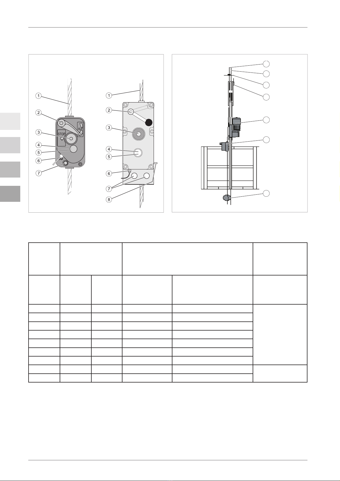
Installation example
See Fig. 1 on
Page 2
.
1 Safety wire rope 5 tirakTM hoists
2 Suspension wire rope 6 blocstopTM BSO
3 Limit switch actuator 7 Tension weight
4 ‘Lifting’ limit switch
Structural conditions
The unit sizes of the different models can be found in Table
2 on Page 55.
The conditions for suspended assemblies can be found in
Table 1 on Page 2.
Nameplate / application restrictions
The nameplate is mounted on the side of the BSO.
Important information about the BSO is listed on the name-
plate (see Fig. 4 on Page 55 as well).
Directives and standards
The Directives and standards that the design is based on
are listed in the Conformity declaration and on
Page 9
.
Product versions covered in the manual
BSO 500, BSO 510, BSO 520, BSO 1000, BSO 1020, BSO
1030, BSO 1040, BSO 2050 and BSO 2360 independent
secondary brakes are described in this manual.
The differing features are the load bearing capabilities
(see Table 1 on
Page 2
) and the unit sizes (see Table 2
on Page 55).
Information about other models can be found in ‘7. Options’
on Page 8 and ‘8. Model versions’ on
Page 9
.
Description4.
Functional description4.1
The BSO monitors the load lifting equipment’s speed. The
BSO will stop the downward movement of the load lifting
equipment if a sudden acceleration occurs, using a friction
actuated connection (clamps) on the safety rope.
The independent secondary brake works automatically.
The speed of the safety rope is permanently monitored by
a centrifugal force balance weight.
The centrifugal force balance weight will activate the clamp-
ing jaws if a sudden acceleration occurs.The clamping jaws
secure the load to the safety rope. The clamping jaws are
self clamping jaws: The clamping jaws automatically shut
tighter if the load moves against the lifting direction. The
greater the tractive force, the tighter the clamping effect
will be.
Therefore the hoisting gear / load lifting equipment is
secured against the snapping of the suspension wire•
rope and
hoist malfunctions (broken gears).•
8 / 60 Rev. 01/2010-EN
EN
Operation and Installation Manual blocstop TM BSO
Safety devices4.5
EMERGENCY-STOP button
Press the EMERGENCY-STOP button to activate the in-
dependent secondary brake manually in an emergency
situation.
Securing in place4.6
The required load bearing capability rating of the suspen-
sion and securing modules depends on the independent
secondary brake model
The design rating for hooking up the safety rope and the
component on which the independent secondary brake will
be secured to must be at least four times the load bearing
capability rating of the independent secondary brake (see
Table 1 on
Page 2
).
The design must ensure that the impact factor remain below
3 (see EN 1808, 6.5.3.6) in the case of personnel lifting
equipment and securing to rigid assemblies.
This is necessary in order to ensure that the dynamic load-
ing is adequate in the event of an emergency stop.
Wire ropes5.
DANGER!
Incorrect wire rope or rope with incorrect diameter!
Using an incorrect rope results in the risk of falling, risk of
injury through falling objects and the danger of malfunc-
tions!
In order to operate safely only utilise original rope–
authorised by Greifzug Hebezeugbau GmbH with the
correct rope diameter and the required design.
The required rope diameter is listed in the table 1 on–
Page 2. The design is listed in the table on Page 14.
Optional accessories6.
Other connecting devices that can be used to secure the
BSOs to different substructures can be supplied if requested
You contact Greifzug Hebezeugbau GmbH directly regard-
ing this matter.
Options7.
The BSO models described here are can also be supplied
with an optional limit switch fitted to them (e.g. blocstop™
BSO 2030 E).
Some models can be supplied with an electrical activation
system if requested. These independent secondary brakes
are to be used in material transport systems only.
Press EMERGENCY-STOP to activate the independent
secondary brake manually in an emergency situation.
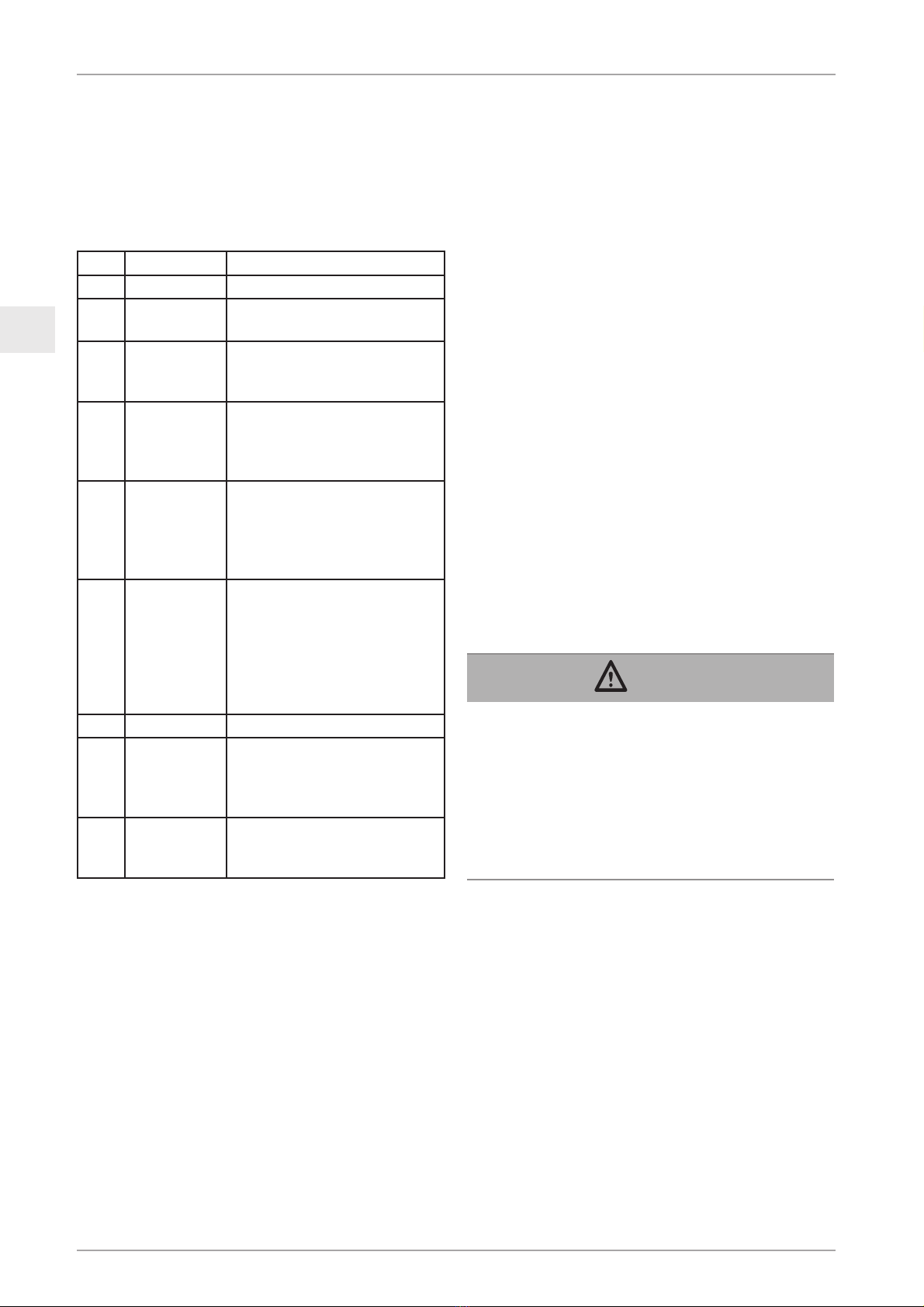
Components / Modules4.2
See Fig. 1 on
Page 2
.
Item Name Function
1 Safety rope
2 Hand-lever Independent secondary brake
release
3 EMERGEN-
CY-STOP
button
Manually activates the inde-
pendent secondary brake
4 inspection
window
Enables you to visually check
the working of the centrifugal
force mechanism whilst it is
working
5 Centrifugal
force weight
Permanently monitors wire
rope speed during the run. The
clamping jaw mechanism will be
activated if the speed setting is
exceeded.
Clamping
jaws
Makes a mechanical connec-
tion between the wire rope and
PAM/MAM in emergency-stop
and activation situations. The
greater the tractive force, the
tighter the clamping effect will
be.
6 Limit switch Optional.
7 Securing
holes
Holds the bolts / screws used
for securing the independent
secondary brake to the attach-
ment parts
8 Control pin Visible with a BSO 2050/2360:
only when the safety rope is
running in correctly.
Technical Specifications4.3
The BSO model specifications (load bearing capability, wire
rope diameter) can be found in Table 1 on
Page 2
.The unit
size can be found in Table 2 on
Page 55
.
Operating substance4.4
Multi-purpose oil / grease (disulfide-free) for lubricating
the safety rope.

9 / 60
EN
Rev. 01/2010-EN
Operation and Installation Manual blocstop TM BSO
Model versions8.
The standard stopping speed of the BSO described here
is 30 m/min. Models with stopping speeds of 40, 60 and
70 m/min can also be supplied if requested.
Necessary accessories9.
An original Greifzug wire rope fitted with a clamp and a
securing device are required in order to be able to monitor
and use the independent secondary brake. This accessory
is not part of the package supplied by us.
The wire rope details can be found in Chapter 5, ‘Wire
ropes’ on Page 8.
Details about the suitable securing devices can be found
in ‘4.6 Securing in place’ on Page 8.
Other original Greifzug accessories: see ‘6. Optional ac-
cessories’ on Page 8.
The operator is responsible for selecting and using the ac-
cessories in compliance with the details.
Installation and10. commissioning
Applicable regulations and10.1 standards
The following Directives and Standards are applicable and
were used:
Machine Directive 98/37/EC; 2006/42/EC as from•
29.12.09
Directive 89/391/EC .•
DIN EN 1808•
ISO 4309 (DIN 15020)•
DIN EN ISO 12100•
The following are also applicable for BSOs fitted with limit
switches or electrical actuators:
Low voltage Directive 2006/95/EC•
The operator is responsible for ensuring that the securing
of the independent secondary brake and the installation
of the suspended assembly complies with the instructions
given in this manual.
Checks to be undertaken10.2 before starting the installation
Checking the suspended assembly
A tested stand that the wire rope can be hung from and
for securing the independent secondary brake. Its strength
rating must be at least four times the load bearing capabil-
ity rating of the independent secondary brake (see Table
1 on Page 2).
Checking the installation site
Inspect the site to ensure that the BSO can be installed
correctly without it being obstructed by other system com-
ponents.
The independent secondary brake must be secured in place
so that the safety rope runs vertically into the independent
secondary brake from above. The independent secondary
brake must be aligned so that it does not touch the safety
rope.The safety rope must be tensioned using a tensioning
weight or a relevant winding device.
The BSO securing unit must be fitted so that the opera-
tor can reach the BSO at any time in order to control a
function or activate an EMERGENCY-STOP. When using
a PAM e.g. on a working platform; when using a MAM at
the operator‘s site.
BSO fitted with a limit switch:
Connection option available in the hoist control box•
Checking the BSOs and the accessories
blocstopTM BSO:
Inspect the casing for any signs of damage.–
Testing the EMERGENCY-STOP button:–
Press the EMERGENCY-STOP button (Trigger the–
independent secondary brake via the triggering
button).
An clear audible click must be heard when it snaps–
shut.
Original Greifzug wire rope
Identified by the red strand of wire•
Diameter must match the independent secondary brake•
model being used
Sufficient length: The load lifting equipment must be•
able to move safely up to the start and end positions,
at least 3m is needed at the end of the wire rope for
the clamp.
No visible damage over the entire length (withdrawal•
criteria as listed in ISO 4309 not yet realised, see DIN
15020 Sheet 2 as well). See Fig. 5 on
Page 56
for
typical wire rope faults.
Welded wire rope ends as shown in Fig. 8 on Page 18.•

10 / 60 Rev. 01/2010-EN
EN
Operation and Installation Manual blocstop TM BSO
DANGER!
Risk of injury through stabs and cuts!
Broken wires can result in protruding wires! Protruding
wires can cut or pierce protective gloves!
Wear suitable leather protective gloves when working–
on wire ropes.
Do not let the wire rope run through your hands.–
Unroll the wire rope correctly (1) so that loops cannot–
occur in the rope (2) (
see Fig. 7 on Page 56
).
Measure the diameter of the rope. The rope diameter–
must match the independent secondary brake model
that is being used, see Table 1 on Page 2).
Secure the wire rope to the suspended assembly. The–
rope must hang free.
Opening the BSO: Press the manual lever downwards–
until it latches into place.
Feed the rope in from the top.–
BSO 2050/2360: The control pin will spring out if the
rope has been fed in correctly.
Use your hands to pull the rope until it is taut.–
Clamp two tension weights (weighing approx. 11.5 kg)–
in place about 20 cm above the ground (see Fig. 9 on
Page 56).
Unroll the end of the rope (3 m or longer) on the ground–
and bind it around at least 3 times.
BSO fitted with a limit switch: Electrical con-
nection
The limit switch will ensure that the control voltage for
the downward hoist movement will be disconnected if an
emergency-stop is activated.
Limit switch cable with plug connection
Connect the limit switch cable plug to the hoist control–
box.
Hard-wired connection
Only a qualified electrician is permitted to undertake this
work.
Connect the limit switch cable inside the hoist control–
box as shown in the circuit diagram.
Commissioning10.4
Determine that everything is ready
Check that the wire rope has been secured correctly–
Inspect the connection between the BSO and the load–
lifting equipment.
The thimbles or sealing cuffs must not be damaged,•
see Fig. 6 on Page 56.
Wire ropes with carabiners: Carabiner is not bent; safety•
catch is intact,
see Fig. 6 on Page 56
.
Securing devices:
Bolts / screws must comply with the details listed in•
Table 1 on Page 2.
Assembly10.3
Requirements
The gap between the safety rope and the suspension•
wire rope must be as small as possible.
Securing module position:The gap between the securing•
module and the hoist must be set up so that the safety
rope runs vertically into the inlet in the BSO.
Fitting the BSO
DANGER!
Danger of severe injuries caused by incorrect secur-
ing!
Both securing holes must be used to secure a blocstop–TM
BSO 2050 or 2360 to the securing module.
The securing module must be fitted with two mounting–
links or similar.
Use 1 bolt / 1 screw (BSO 500/1000) or 2 bolts / 2–
screws (BSO 2000) to secure the BSO to the securing
module.
Use a cotter pin or a comparable safety device to stop–
the bolts from being lost.
Use screws with self-locking nuts to stop them from–
being lost.
Mount the rope
DANGER!
Incorrect assembly!
Can result in damage to the rope and therefore severe
injuries by incorrect securing!
Never pull the rope over edges.–
The loose rope end must hang free.–

11 / 60
EN
Rev. 01/2010-EN
Operation and Installation Manual blocstop TM BSO
The inspection results must be recorded in the log-–
book.
Function test
Shut the BSO by pressing the EMERGENCY-STOP–
button.
The manual lever must jump into the SHUT position.
Now try to pull the rope upwards.–
DANGER!
Danger of severe injuries and falling off caused by
malfunctions, incorrect use and incorrect operation!
If you can pull the wire rope upwards:
Do not use the system!–
Dismantle the BSO and send it for repair or replace it–
with another BSO that works correctly!
If you cannot pull the wire rope upwards:
Release the BSO by pressing the manual lever down-–
wards into the OPEN position.
Pull the wire rope upwards sharply.–
The independent secondary brake must snap shut
automatically.
The system can be used if both tests were successful.
DANGER!
Danger of severe accidents and falling off as a result
of a BSO malfunction!
If the independent secondary brake does not snap shut:
Do not use the system!–
Dismantle the BSO and send it for repair or replace it–
with another BSO that works correctly!
Operating / Working11.
Personnel must have been trained by the operator in operat-
ing the BSO and be authorised to use it.
Checking before starting work11.1
DANGER!
Risk of injury through stabs and cuts!
Broken wires can result in protruding wires! Protruding
wires can cut or pierce protective gloves!
Wear suitable leather protective gloves when working–
on wire ropes.
Do not let the wire rope run through your hands.–
Check that the wire rope has been secured correctly.–
Inspect the connection between the BSO and the load–
lifting equipment.
The inspection results must be recorded in the log-–
book.
Run the function test (see ‘Function test’ on Page 11).–
Working with a PAM11.2
DANGER!
Danger of being injured due to the emergency-stop
drop being too long!
The wire rope will be pushed upwards when moving up-
wards with the BSO shut and it will no longer be tensioned
between the suspension point and the BSO.
You must always ensure that the manual lever is set to–
OPEN before moving.
Push the BSO manual lever downwards (OPEN posi-–
tion).
Start the hoisting gear.–
Check the inspection window at least once during each–
movement to see that the centrifugal force weight is
turning.
A function test must be run if the centrifugal force weight
is not turning.
Move the load lifting equipment slowly and carefully–
downwards.
Test the BSO as described in ‘10.4 Commissioning’ on–
Page 10.
Wire rope is not tensioned
If the safety rope was released when the BSO snapped
shut:
Stop the hoisting gear.–
Check to see if the rope is hanging free.–
Open the BSO and, if necessary, move downwards–
slowly.
Only continue with the original movement after the rope–
has been re-tensioned.
Working with a MAM11.3
Push the BSO manual lever downwards (OPEN posi-–
tion).
Start the hoisting gear.–
Wire rope is not tensioned
If the rope was released when the BSO snapped shut:

12 / 60 Rev. 01/2010-EN
EN
Operation and Installation Manual blocstop TM BSO
Move the PAM carefully downwards and be ready to–
press the EMERGENCY-STOP button on the BSO at
any time.
Run a BSO function test afterwards as described in–
‘10.4. Commissioning’ on Page 10. Change the BSO if
necessary and have it repaired.
Measures to be taken when using12.2 a MAM
DANGER!
Danger of being injured by a falling load!
Never stand beneath a MAM.–
Check out the cause of the problem.–
Eliminate the problem.–
If the problem was caused by the suspension wire snapping
or a hoist malfunction:
Implement suitable measures to secure the MAM in–
place so that the suspension rope or the hoist can be
changed. Consult the MAM documentation.
If the problem was not caused by the suspension wire
snapping or a hoist malfunction:
Try to move upwards.–
If this is not possible:
Secure the MAM in place (see above).–
If you can move upwards then you probably have a BSO
problem.
Open the BSO by pressing the manual lever down-–
wards.
Move the MAM carefully downwards.–
Run a BSO function test afterwards as described in–
‘10.4 Commissioning’ on Page 10. Change the BSO if
necessary and have it repaired.
Measures to be taken after a12.3 problem or an emergency-stop
After a problem:
Dismantle the BSO and send it to Greifzug Hebezeugbau–
GmbH for testing.
After every emergency-stop: Checks to be
carried out by a specialist
Wire rope inspection.
Check the wire rope suspension point.–
Stop the hoisting gear.–
Check to see if the rope is hanging free.–
Open the BSO and, if necessary, move downwards–
slowly.
Only continue with the original movement after the rope–
has been re-tensioned.
Manual EMERGENCY-STOP11.4
The BSO can be snapped shut at any time whilst moving
by pressing the EMERGENCY-STOP button. The load will
then be stopped by the safety rope.
Measures to be taken12. immediately after an
emergency-stop
Emergency-stop means that the BSO has activated as a
result of the suspension rope or hoist being damaged.
Measures to be taken when using12.1 a PAM
DANGER!
Danger of severe injuries caused by incorrect proce-
dures!
Keep calm.–
Check for the cause.–
Eliminate the problem.–
If the problem was caused by the suspension wire snapping
or a hoist malfunction:
Evacuate the team. Consult the PAM documentation or,–
if available, the operator’s emergency rescue plan.
Implement suitable measures to secure the PAM in–
place so that the suspension rope or the hoist can be
changed.
If the problem was not caused by the suspension wire
snapping or a hoist malfunction:
Try to move upwards.–
If this is not possible:
Evacuate the team and secure the PAM in place (see–
above).
If you can move upwards then you probably have a BSO
problem.
Open the BSO by pressing the manual lever down-–
wards.

13 / 60
EN
Rev. 01/2010-EN
Operation and Installation Manual blocstop TM BSO
Check the connection between the BSO and the secur-–
ing module or PAM / MAM.
An inspection is not required if it was activated (the EMER-
GENCY-STOP button was pressed).
Predictable misuse13.
Guarantee and liability claims for injuries to personnel or
damaged equipment will be rejected if they can be traced
back to one or more of the following causes:
Unauthorised use of the equipment•
Operation with a soiled rope•
Not adhering to the stipulated maintenance periods•
Incorrect BSO installation, commissioning, operation,•
maintenance or repairs
Cleaning with a high-pressure cleaner•
Poor monitoring of the part and the accessories, which•
has resulted in wear occurring
Incorrect and unauthorised repairs were carried out•
Non-original spare parts were used•
Safety device settings were altered•
Measurements and checks to detect early signs of dam-•
age were neglected.
BSO was overloaded•
Manual lever was jammed / wedged in place•
The BSO was installed on the suspension rope•
The safety wire rope was anchored to the same anchor-•
ing point as the suspension wire rope
Load lifted when the safety wire rope was slack•
A PAM was used with a hoist that had a wire rope speed•
faster than 18 m/min
A catastrophe cause by foreign bodies or force ma-•
jeure
Dismantling14.
DANGER!
Risk of injury through stabs and cuts!
Broken wires can result in protruding wires! Protruding
wires can cut or pierce protective gloves!
Wear suitable leather protective gloves when working–
on wire ropes.
Do not let the wire rope run through your hands.–
Disconnect the tension weight from the safety rope.–
Open the BSO by pressing the manual lever downwards–
until it latches into place.
Pull the safety rope out by hand.–
Dismantling the BSO: Unscrew the bolts or screws.–
Roll up the wire rope correctly (1) so that loops that–
will make the rope unusable cannot occur (2) (see Fig.
7 on Page 56).
Transport and storage15.
Prevent the BSO from being damaged whilst it is being–
transported.
The BSO must be stored in a dry, dust-free location that–
has a stabile ambient temperature.
Maintenance16.
Authorised maintenance person-16.1 nel
DANGER!
Risk of falling! Risk of being injured by falling ob-
jects!
Mortal danger due to incorrectly performed maintenance
and service work!
Maintenance and service work which require the BSO to
be opened may only be performed by the following autho-
rised parties:
Greifzug Hebezeugbau GmbH–
Lifting equipment service companies authorised by–
Greifzug Hebezeugbau GmbH
Service personnel trained and certified by Greifzug–
Hebezeugbau GmbH
Inspection requirements16.2
A written inspection certificate must be produced for the
annual inspection and any extraordinary inspections. The
inspections must be recorded in an inspection logbook.
Prior to use
The correct working state of the BSO, the safety rope and
the securing devices must be always be checked before
use, see
‘11.1 Checking before starting work’ on
Page 11
.
Annual safety test
A safety test must be run once a year.
We recommend that the system is tested by Greifzug He-
bezeugbau GmbH.
Contact Greifzug Hebezeugbau GmbH or your dealer–
with regards to this test.
14 / 60 Rev. 01/2010-EN
EN
Operation and Installation Manual blocstop TM BSO
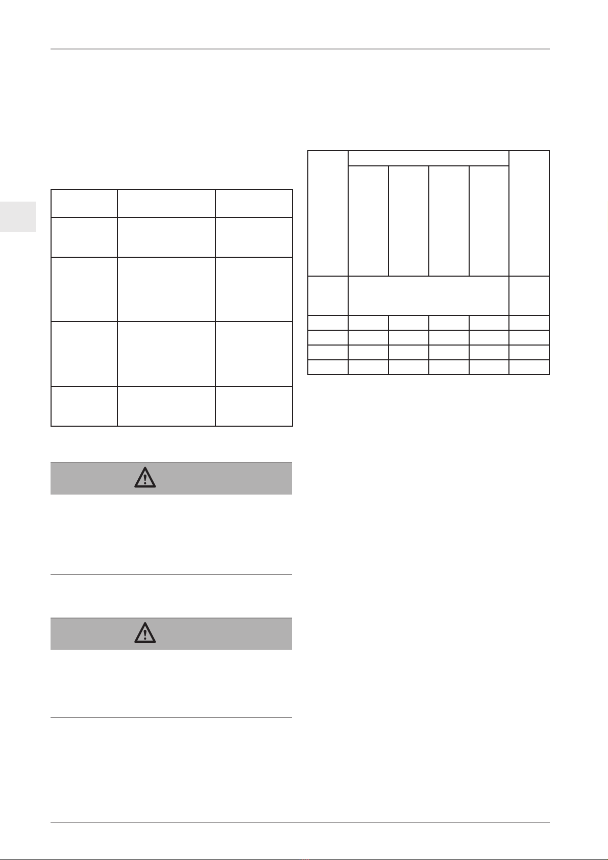
Replacement
Replace the ropes immediately if the withdrawal criteria
in accordance with the table below have been reached (to
ISO 4309 and DIN 15020, sheet 2) or typical rope defects
have occurred, see fig. 5 on Page 56.
Nominal diameter of the
rope
Design of the rope
max. permitted reduction
of the diameter
Rotation arm
4 x 26 5 x 19 5 x 26
[mm] Number of visible wire breaks in the
outer wires along a length of 30 x nomi-
nal diameter of the rope.
[mm]
8 10 8 11 7,6
9 10 10 8 8,5
10 8 11 9,3
14 10 11 13,1
Move the manual lever up to the stop to open the BSO–
and hold it there.
Now pull the rope out.–
Fitting a new rope, see ‘10.3 Assembly’ on Page 10.–
Extraordinary test
A specialist must test the operating safety of the BSO after
an emergency-stop has taken place, see ‘12.3 Measures
to be taken after a problem or an emergency-stop’ on
Page 12.
Care and maintenance16.3
Interval Work Implementa-
tion
1 x week Lubricate the safe-–
ty rope
Clean the BSO–
Operating per-
sonnel
1 x annually
or every
250 running
hours
Inspect for clamp-–
ing jaw wear
Check for pres-–
sure / drive roller
wear
Authorised
maintenance
personnel, see
page 13
Whenever
necessary
Replace clamping–
jaws
Replace the pres-–
sure / drive roll-
ers
Authorised
maintenance
personnel, see
page 13
Whenever
necessary
Replace the safety–
rope
Trained person
nominated by
the operator
Rope
DANGER!
Risk of injury through stabs and cuts!
Broken wires can result in protruding wires! Protruding
wires can cut or pierce protective gloves!
Wear suitable leather protective gloves when working–
on wire ropes.
Do not let the wire rope run through your hands.–
Lubrication
DANGER!
Danger of falling caused by a slippery safety rope!
Might result in severe injuries or even death!
Never lubricate the safety rope using a lubricant that–
contains disulfide (e.g. Molycote®).
Use multi-purpose grease or oil.–
Cleaning
Brush off soiled ropes when dry if necessary. Lubricate
again if necessary.

15 / 60
EN
Rev. 01/2010-EN
Operation and Installation Manual blocstop TM BSO
Troubleshooting18.
Problem Cause Clearing
BSO cannot be opened BSO is holding the load on the•
safety wire rope
Mechanical defect•
Move the load upwards on the suspension–
wire rope
Change the BSO and send it back for re-–
pair
Equipment activated by nor-
mal downwards travel
Hoisting gear speed too fast•
Activation speed setting is too•
low
Check the hoist–
Change the BSO and send it back for re-–
pair
Centrifugal force weight
does not turn
Dirty or defective•
Iced up•
Change the BSO and clean it or send it back–
for repair
Carefully use hot air to heat it up (70°C–
max).
BSO 2050/2360:
Control pin is not visible
after the safety rope has
been fed in.
Rope has not been fed in cor-•
rectly
Mechanical defect•
Pull the rope out and feed it back in cor-–
rectly
Change the BSO and send it back for re-–
pair
BSO fitted with a limit
switch:
The hoisting gear cannot be
move upwards.
Limit switch connection with the•
hoist controller has failed
Defective limit switch•
Plug the connection in–
Have the limit switch checked by an electri-–
cian and return the BSO for repair if neces-
sary.
Disposal and environmental17. protection
The equipment is made from recyclable materials. The
equipment must be disposed of correctly if it is to be scraped
later on.The national versions of the waste legislation Direc-
tive 75/442/EC apply within the European Union.
In accordance with Directive 2002/96/EC, the manufacturer
is obliged to take back and dispose of specific electrical and
electronic components.The following symbol is used on the
nameplate of such components to identify them:

16 / 60 Rev. 12/2009-DE
DE
Montage- und Bedienungsanleitung blocstop™ BSO
11. Bedienung/Betrieb ....................................24
11.1 Prüfungen vor Arbeitsbeginn .............24
11.2 Betrieb mit einem PAM......................24
11.3 Betrieb mit einem MAM .....................25
11.4 Manueller NOT-STOP ........................25
12. Sofortmaßnahmen im Fangfall.................25
12.1 Maßnahmen bei einem PAM..............25
12.2 Maßnahmen bei einem MAM.............25
12.3 Maßnahmen nach einer Störung
oder einem Fangfall...........................26
13. Naheliegender Missbrauch.......................26
14. Demontage.................................................26
15. Transport und Lagerung...........................26
16. Instandhaltung...........................................26
16.1 Autorisiertes Wartungspersonal.........26
16.2 Erforderliche Prüfungen.....................27
16.3 Pflege und Wartung...........................27
17. Entsorgung und Umweltschutz................28
18. Fehlersuche/Störungsbeseitigung...........28
Inhaltsverzeichnis
1. Allgemeines ...............................................17
1.1 Verwendete Begriffe und
Abkürzungen .....................................17
1.2 Verwendete Symbole.........................18
2. Sicherheit...................................................18
2.1 Allgemeine Sicherheitshinweise ........18
2.2 Hinweise für den Betreiber ................19
2.3 Verantwortung des
Anlagenherstellers.............................19
3. Übersicht....................................................19
3.1 Lieferzustand.....................................19
3.2 Lieferumfang......................................19
3.3 Gerätebeschreibung ..........................20
4. Beschreibung ............................................20
4.1 Funktionsbeschreibung......................20
4.2 Komponenten/Baugruppen ................21
4.3 Technische Daten..............................21
4.4 Betriebsmittel ....................................21
4.5 Sicherheitseinrichtungen ...................21
4.6 Befestigung .......................................21
5. Seile ...........................................................21
6. Optionales Zubehör ..................................22
7. Optionen ....................................................22
8. Modellvarianten.........................................22
9. Notwendiges Zubehör...............................22
10. Installation und Inbetriebnahme ..............22
10.1 Anzuwendende Regeln und
Normen .............................................22
10.2 Prüfungen vor Beginn der
Montage ............................................22
10.3 Montage ............................................23
10.4 Inbetriebnahme .................................24
GEFAHR!
Gefahr von schweren Unfällen und Absturz durch
Fehlfunktionen, falsche Nutzung und Fehlbedienung!
Lesen Sie diese Anleitung sorgfältig durch, bevor Sie dieses
Gerät montieren und in Betrieb nehmen. Beachten Sie
die Hinweise und Verhaltensregeln, die für einen sicheren
Betrieb des Geräts notwendig sind
Beachten Sie diese Anleitung nicht:
können schwerste Verletzungen und der Tod die Folge–
sein
können Schäden am Gerät entstehen.–

17 / 60
DE
Rev. 12/2009-DE
Montage- und Bedienungsanleitung blocstop™ BSO
Allgemeines1.
Ausgabedatum
4. Auflage: Januar 2010
Urheberrecht
Das Urheberrecht an dieser Anleitung verbleibt bei der
Greifzug Hebezeugbau GmbH.
Diese Anleitung ist nur für den Betreiber der darin be-
schriebenen Anlagen sowie dessen Personal bestimmt. Die
Anleitung muss dem Bediener jederzeit zugänglich sein.
Weitere Exemplare können angefordert werden.
Ohne Zustimmung der Greifzug Hebezeugbau GmbH dürfen
keine Bestandteile dieser Anleitung vervielfältigt, verbreitet
oder anderweitig mitgeteilt werden.
Zuwiderhandlungen können strafrechtliche Folgen haben.
Anschrift des Herstellers
Verkaufs- und Servicestelle:
Greifzug Hebezeugbau GmbH
Scheidtbachstraße 19-21
51469 Bergisch Gladbach, Deutschland
Postfach 20 04 40
51434 Bergisch Gladbach, Deutschland
Telefon: +49 (0) 22 02 / 10 04-0
Telefax: +49 (0) 22 02 / 10 04-50 + 70
Die Greifzug Hebezeugbau GmbH behält sich das Recht
vor, im Zuge der Produktverbesserung jegliche Änderungen
an dem in dieser Montage- und Bedienungsanleitung be-
schriebenen Produkt vorzunehmen.
Kunden können über die Unternehmen der TRACTEL-
Gruppe und die von der TRACTEL-Gruppe autorisierten
Instandhalter auf Anfrage Dokumentationen über andere
TRACTEL-Produkte erhalten: Hebezeuge und deren Zube-
hör, fest installierte oder mobile Arbeitsbühnen zur Innen-
und Außenbefahrung von Gebäuden, Anschlagmittel, Ab-
fangsicherungen für Lasten, Persönliche Schutzausrüstung
gegen Absturz, Zugkraft- und Seilspannungsmessgeräte,
etc. Besuchen Sie hierfür auch die TRACTEL-Website
www.tractel.com.
Die TRACTEL-Gruppe und ihr Händlernetzwerk bieten Ihnen
bei Bedarf zusätzlich Kunden- und Reparaturservice.
Verwendete Begriffe und1.1 Abkürzungen
In dieser Montage- und Bedienungsanleitung haben die
folgenden Begriffe diese Bedeutung:
Anlage
Mit Anlage wird die Einrichtung bezeichnet (z. B. eine Ar-
beitsbühne), in die das Gerät eingebaut wird.
Anlagenhersteller
Der Anlagenhersteller (Anlagenplaner, Anlagenhersteller,
Montagebetrieb) ist der Inverkehrbringer der Anlage und
aller notwendigen Komponenten. Der Anlagenhersteller
ist für den Entwurf, die Herstellung, den Einbau und das
Inverkehrbringen verantwortlich.
Auslösefall
Auslösen der Fangvorrichtung (NOT-STOP-Situation) her-
vorgerufen durch manuelles Auslösen oder unkontrolliertes
Auslösen durch Vibrationen.
Betreiber
Der Betreiber ist für den ordnungsgemäßen Betrieb der
Anlage/des Geräts sowie für die Einhaltung der Wartungsin-
tervalle und die Durchführung der Instandsetzungsarbeiten
verantwortlich.
Bediener
Person, die vom Betreiber in die Bedienung des Produktes
eingewiesen und mit dem Gebrauch betraut ist.
Bediener (PAM)
Eine benannte und für Arbeiten in der Höhe entsprechend
ausgebildete Person, die durch ihre Kenntnisse und prakti-
schen Erfahrungen in der Lage ist, mit den benötigten
An-weisungen versehen, die erforderlichen Bedienschritte
auszuführen.
BSO
Im Text wird BSO als Abkürzung für die hier beschriebenen
Modelle der Fangvorrichtung blocstopTM BSO verwendet.
Elektrofachkraft
Elektrofachkraft ist, wer über ausreichende Kenntnisse ver-
fügt oder durch eine Ausbildung die notwendigen Qualifikati-
onen erworben hat, Risiken zu erkennen und Gefährdungen
zu vermeiden, die von der Elektrizität ausgehen können.
Fangfall
Auslösen der Fangvorrichtung (Not-Stop-Situation) bei
Tragseilbruch oder Fehlfunktion der Winde.
Fangvorrichtung
Vorrichtung zum Abfangen von Lastaufnahmemitteln für
Material oder Personen bei Tragseilbruch oder Störungen,
z. B. Versagen des Antriebs.
Hebezeug
Vorrichtung zum Heben von Lastaufnahmemitteln (LAM).
Kunde/Endkunde
Der Kunde oder Endkunde ist der Kunde des Anlagenher-
stellers und kann gleichzeitig auch der Betreiber sein.

18 / 60 Rev. 12/2009-DE
DE
Montage- und Bedienungsanleitung blocstop™ BSO
Materialaufnahmemittel (MAM)
Lastaufnahmemittel für Material.
Personenaufnahmemittel (PAM)
Lastaufnahmemittel für Personen. Hierzu zählen auch
Kombinationen von Lastaufnahmemitteln für Material und
Personen.
Lastaufnahmemittel (LAM)
Bauteil oder Ausrüstungsteil zum Heben von Personen
(Arbeitskorb, Arbeitsbühne, Arbeitssitz) oder Material. Das
Bauteil oder das Ausrüstungsteil kann z. B. zwischen Last
und Winde angebracht sein oder selbst Teil der Last sein.
Sachkundige Person
Eine benannte und entsprechend ausgebildete Person, die
durch ihre Kenntnisse und praktischen Erfahrungen in der
Lage ist, mit den benötigten Anweisungen die erforderlichen
Arbeiten sicher auszuführen.
Wartungspersonal
Eine benannte und von der Greifzug Hebezeugbau GmbH
geschulte Person mit gültigem Zertifikat, die in der Lage ist,
mit den benötigten Anweisungen versehen, die erforderli-
chen Wartungs-, Prüf- und Instandsetzungsarbeiten sicher
auszuführen.
Verwendete Symbole1.2
GEFAHR!
Art und Quelle der Gefahr.
Folge: z.B. Tod oder schwere Verletzungen.
Maßnahmen, mit denen die Gefahr vermieden wird.–
ACHTUNG!
Art und Quelle der Gefahr.
Folge: z.B. Sachschäden oder Umweltschäden.
Maßnahmen, mit denen Schäden vermieden werden.–
Hinweis:
Dieses Symbol kennzeichnet keine Sicherheitshinweise,
sondern gibt Informationen zum besseren Verständnis
der Abläufe.
Sicherheit2.
Allgemeine Sicherheitshinweise2.1
GEFAHR!
Gefahr von schweren Unfällen und Absturz durch
Fehlfunktionen, falsche Nutzung und Fehlbedienung!
Beachten Sie folgende Angaben, damit der sichere–
Betrieb und die ordnungsgemäße Funktion des Gerätes
gewährleistet sind:
Fehlerhafte oder beschädigte Fangvorrichtungen, Seile–
oder Anschlagmittel dürfen nicht eingesetzt werden.
Der BSO darf nur mit einem Original-Greifzug-Seil mit–
dem in dieser Anleitung angegebenen Seildurchmesser
verwendet werden.
Befestigungsmittel müssen den Angaben in dieser–
Anleitung bzw. den gültigen Normen/Richtlinien ent-
sprechen.
Instandsetzungs- und Wartungsarbeiten dürfen nur–
von autorisiertem Wartungspersonal durchgeführt
werden, siehe ‚16.1 Autorisiertes Wartungspersonal‘
auf Seite 26.
Die zulässige Tragfähigkeit der Fangvorrichtung darf–
nicht überschritten werden.
Montage und Bedienung dürfen nur durch geschultes–
und eingewiesenes Personal unter Berücksichtigung
dieser Montage- und Bedienungsanleitung erfolgen.
Die Fangvorrichtung muss so befestigt sein, dass das Si-–
cherheitsseil von oben senkrecht in die Fangvorrichtung
einläuft. Die Fangvorrichtung muss sich frei am Sicher-
heitsseil ausrichten können. Das Sicherheitsseil muss
mit einem Spanngewicht oder einer entsprechenden
Aufwickelvorrichtung gespannt sein.
Das Sicherheitsseil darf nicht mit Disulfid-haltigen–
Schmierstoffen (z. B. Molycote™) geschmiert werden,
siehe ‚16.3 Pflege und Wartung‘ auf Seite 27.
Das Reinigen des Seils oder von Fangvorrichtungen–
mit einem Hochdruckreiniger ist verboten! Eindringende
Feuchtigkeit führt zu Fehlfunktionen.
Schmutz am Seil führt zum vorzeitigen Verschleiß oder–
zur Zerstörung von Seil, Anschlagmittel und Fangvor-
richtung.
Arbeiten an elektrischen Ausrüstungen dürfen nur von–
einer Elektrofachkraft oder von unterwiesenen Personen
unter Leitung und Aufsicht einer Elektrofachkraft gemäß
den elektrotechnischen Normen, Vorschriften und Re-
geln vorgenommen werden.

19 / 60
DE
Rev. 12/2009-DE
Montage- und Bedienungsanleitung blocstop™ BSO
Die Schraubverbindungen zur Befestigung des BSO–
und der Spannvorrichtung müssen gemäß der bautech-
nischen Ausführung ausgelegt werden.
Die Informationen und Hinweise dieser Montage- und–
Bedienungsanleitung müssen in die Betriebsanleitung
und Dokumentation des Anlagenherstellers eingear-
beitet und durch anlagenspezifische Angaben ergänzt
werden. Eine einfache Weitergabe dieser Anleitung an
den Betreiber ist nicht ausreichend.
Insbesondere folgende Informationen müssen von Ihnen be-
achtet und dem Betreiber zur Verfügung gestellt werden:
Da die Greifzug Hebezeugbau GmbH den späteren An-–
wendungsfall der hier beschriebenen Fangvorrichtungen
nicht kennt, ist der Anlagenhersteller dazu verpflichtet,
den Endkunden bzw. Betreiber über weitere Sicherheits-
hinweise sowie über ergänzende Wartungsarbeiten zu
informieren.
Angaben zur Wartung der Fangvorrichtung und des–
Zubehörs müssen in das Wartungsheft der Anlage
eingearbeitet werden.
Übersicht3.
Lieferzustand3.1
Die BSOs (Fangvorrichtungen) werden komplett montiert
geliefert.
Lieferumfang3.2
Fangvorrichtung blocstop™ BSO mit Übergeschwindig-•
keitsautomatik
Original-Greifzug™-Seil gemäß Bestellspezifikation•
Original-Montage- und Bedienungsanleitung•
Logbuch•
Prüfzertifikate•
Lieferumfang optional:
Stromlaufplan (bei BSOs mit Endschalter)•
Verbindungsmittel•
Hinweise für den Betreiber2.2
Ist mehr als eine Person mit einer der hier beschrie-–
benen Tätigkeiten betraut, so hat der Betreiber einen
Aufsichtführenden zu bestimmen, der weisungsbefugt
ist.
Der Betreiber ist dafür verantwortlich, klare Bedie-–
nungs-, Instandhaltungs-, Wartungs- und sonstige Be-
triebsanweisungen bereitzustellen und durch Schulung
und Anweisung des Personals den sachgerechten und
bestimmungsgemäßen Betrieb und die sachgerechte
Bedienung des BSO sicherzustellen.
Der Betreiber ist für den ordnungsgemäßen Betrieb–
der Anlage sowie für die Einhaltung der Wartungsin-
tervalle und die Durchführung von Wartungsarbeiten
verantwortlich.
Der Betreiber ist verpflichtet, das mitgelieferte Logbuch–
zu führen.
Die nationalen Regelungen zum Arbeitsschutz sind zu–
beachten. Innerhalb der Europäischen Union gilt die
EU-Richtlinie 89/391/EWG (in Deutschland die Be-
triebssicherheitsverordnung (BetrSichV)). Die nationalen
Arbeitsschutzbestimmungen im Betreiberland müssen
beachtet werden.
Ein Exemplar dieser Anleitung muss dem beauftragten–
Personal ausgehändigt werden und jederzeit zugäng-
lich sein.
Für die Wahl der Befestigungsmethode und geeignete–
Anschlagmöglichkeiten ist der Betreiber der Anlage
verantwortlich.
Befestigungsmittel müssen den Angaben in dieser–
Anleitung bzw. den gültigen Normen/Richtlinien ent-
sprechen.
Bei der Verwendung anderer als der Original-Teile,–
insbesondere eines anderen als des vorgeschriebenen
Seils, entfällt der Garantieanspruch gegenüber dem
Hersteller und die CE-Kennzeichnung verliert ihre
Gültigkeit.
Beachten Sie den zulässigen Temperaturbereich, siehe–
‚Einsatzbereich‘ auf Seite 20.
Verantwortung des2.3 Anlagenherstellers
Der Anlagenhersteller ist für den Entwurf, die Herstel-–
lung, den Einbau und das Inverkehrbringen sowie für
die CE-Kennzeichnung der Anlage und die Ausstellung
der EG-Konformitätserklärung verantwortlich.
Die im Lieferumfang der Greifzug Hebezeugbau GmbH–
enthaltenen Produkte müssen vom Anlagenhersteller
sorgfältig ausgewählt, bestimmungsgemäß verwendet
und gemäß den Angaben dieser Montage- und Bedie-
nungsanleitung montiert werden.

20 / 60 Rev. 12/2009-DE
DE
Montage- und Bedienungsanleitung blocstop™ BSO
Gerätebeschreibung3.3
Bestimmungsgemäßer Gebrauch
Der blocstop™ BSO mit Übergeschwindigkeitsautomatik ist
eine Fangvorrichtung, die bei jedem Hebezeug/Lastaufnah-
memittel für gewerbliche Zwecke eingesetzt werden kann.
Der BSO ist nicht für die private Verwendung vorgesehen.
Der genaue Verwendungszweck wird durch den Betreiber
bzw. Anlagenhersteller festgelegt.
Der BSO darf nur mit einem Original-Greifzug-Seil mit
dem in dieser Anleitung angegebenen Seildurchmesser
verwendet werden.
Bis auf den blocstop™ BSO 510 dürfen alle hier beschrie-
benen Geräte als Fangvorrichtung für Personen- und Ma-
terialaufnahmemittel eingesetzt werden.
blocstop™ BSO 510 darf nur bei Lastaufnahmemitteln für
Material eingesetzt werden.
Der BSO entspricht dem Stand der Technik sowie den
geltenden Sicherheitsbestimmungen zum Zeitpunkt des
Inverkehrbringens.
Instandsetzungs- und Wartungsarbeiten am BSO dürfen nur
von sachkundigen Personen durchgeführt werden, siehe
‚16.1 Autorisiertes Wartungspersonal‘ auf Seite 26.
Der BSO darf nicht in Anlagen eingebaut werden, die der
Richtlinie 95/16/EG (Aufzugsrichtlinie, in Deutschland: 12.
GPSGV) entsprechen müssen.
Jede von den hier genannten Angaben abweichende Ver-
wendung gilt als nicht bestimmungsgemäß. Für hieraus
resultierende Schäden haftet die GREIFZUG Hebezeug-
bau GmbH nicht. Das Risiko trägt allein der Betreiber.
Zur bestimmungsgemäßen Verwendung gehört auch das
Beachten aller Hinweise aus der Montage- und Bedienungs-
anleitung, insbesondere die Einhaltung der Montage- und
Instandhaltungsvorschriften.
Gewährleistungs- und Haftungsausschlüsse
Siehe ‚13. Naheliegender Missbrauch‘ auf Seite 26.
Einsatzbereich
Die Fangvorrichtung blocstopTM BSO ist für alle Lastaufnah-
memittel/Hebezeuge unter folgenden Betriebsbedingungen
geeignet:
Für Festeinbauten oder wechselnde Installationen•
Für kurzfristigen Betrieb•
In Höhenlagen bis maximal 1000 m über NN•
Bei Temperaturen zwischen -25 und +70 °C•
GEFAHR!
Gefahr von schweren Unfällen und Absturz durch
Fehlfunktionen oder Explosionen!
Der BSO darf nicht im 24h-Betrieb betrieben werden.–
Der BSO darf nicht in explosionsgefährdeten Bereichen–
betrieben werden.
Einbaubeispiel
Siehe Abb. 1 auf Seite 2.
1 Sicherheitsseil 5 tirakTM-Winde
2 Tragseil 6 blocstopTM BSO
3 Auslöser für Endschal-
ter
7 Spanngewicht
4 Endschalter ‚Heben‘
Bauliche Voraussetzungen
Die Einbaumaße der verschiedenen Modelle finden Sie in
Tabelle 2 auf Seite 55.
Die Voraussetzungen für tragende Konstruktionen finden
Sie in Tabelle 1 auf Seite 2.
Typenschild/Grenzen der Anwendung
Das Typenschild befindet sich seitlich am BSO.
Auf dem Typenschild finden Sie notwendige Informationen
über den BSO (siehe auch Abb. 4 auf Seite 55).
Richtlinien und Normen
Die zugrundeliegenden Richtlinien und Normen finden Sie
in der Konformitätserklärung und auf Seite 22.
Produktvarianten in der Anleitung
In dieser Anleitung werden die Fangvorrichtungen BSO 500,
BSO 510, BSO 520, BSO 1000, BSO 1020, BSO 1030, BSO
1040, BSO 2050 und BSO 2360 beschrieben.
Unterscheidungsmerkmale sind die Tragfähigkeit (siehe
Tabelle 1 auf Seite
2
) und die Einbaumaße (siehe Tabelle
2 auf Seite 55).
Informationen über weitere Modelle finden Sie unter ‚7.
Optionen‘ und ‚8. Modellvarianten‘ auf Seite
22
Beschreibung4.
Funktionsbeschreibung4.1
Der BSO überwacht die Geschwindigkeit des Lastaufnah-
memittels. Bei Übergeschwindigkeit stoppt der BSO die
This manual suits for next models
8
Table of contents
Languages:


