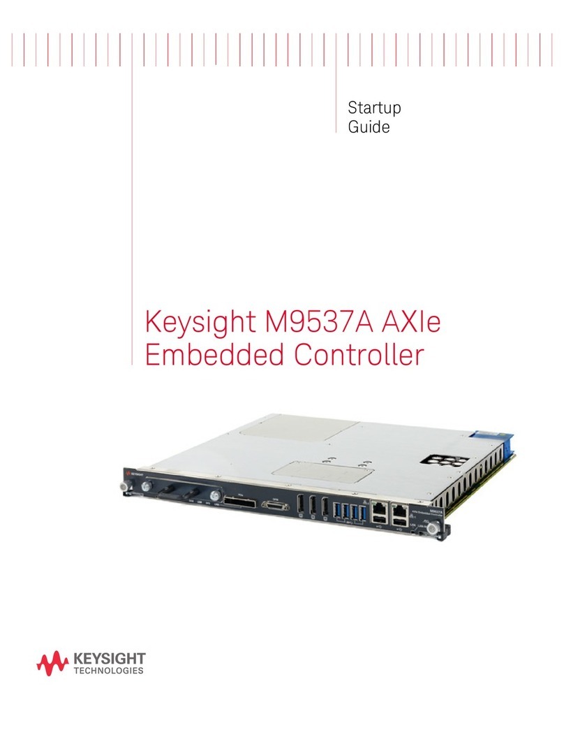
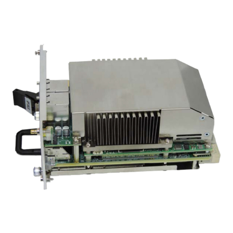
Keysight Technologies M9037A User manual

Keysight M9037A PXIe
Embedded Controller
User
Guide


iii
Notices
© Keysight Technologies, Inc. 2014-2019
No part of this manual may be repro-
duced in any form or by any means
(including electronic storage and retrieval
or translation into a foreign language)
without prior agreement and written con-
sent from Keysight Technologies, Inc. as
governed by United States and interna-
tional copyright laws.
Manual Part Number
M9037-90005
Edition
Eighth Edition, October 2019
Published in USA
Keysight Technologies, Inc.
1400 Fountaingrove Parkway
Santa Rosa, CA 95403 USA
Trademarks
AXIe is a registered trademark of the AXIe
Consortium.
PXI is a registered trademark of the PXI
Systems Alliance.
PICMG®, Compact PCI®, and
AdvancedTCA®are registered trade-
marks of the PCI Industrial Computer
Manufacturers Group.
PCI-SIG®, PCI Express®, and PCIe®are
registered trademarks of PCI-SIG.
Sales and Technical Support
To contact Keysight for sales and techni-
cal support, refer to the support links on
the following Keysight websites:
www.keysight.com/find/M9037A (prod-
uct-specific information and support,
software and documentation updates)
www.keysight.com/find/assist (world-
wide contact information for repair and
service)
Declaration of Conformity
Declarations of Conformity for this prod-
uct and for other Keysight products may
be downloaded from the Web. Go to
http://www.keysight.com/go/conformity
and click on “Declarations of Conformity.”
You can then search by product number
to find the latest Declaration of Confor-
mity.
Technology Licenses
The hardware and/or software described
in this document are furnished under a
license and may be used or copied only in
accordance with the terms of such
license.
Warranty
THE MATERIAL CONTAINED IN THIS
DOCUMENT IS PROVIDED “AS IS,” AND
IS SUBJECT TO BEING CHANGED,
WITHOUT NOTICE, IN FUTURE EDI-
TIONS. FURTHER, TO THE MAXIMUM
EXTENT PERMITTED BY APPLICABLE
LAW, KEYSIGHT DISCLAIMS ALL WAR-
RANTIES, EITHER EXPRESS OR IMPLIED,
WITH REGARD TO THIS MANUAL AND
ANY INFORMATION CONTAINED
HEREIN, INCLUDING BUT NOT LIMITED
TO THE IMPLIED WARRANTIES OF MER-
CHANTABILITY AND FITNESS FOR A
PARTICULAR PURPOSE. KEYSIGHT
SHALL NOT BE LIABLE FOR ERRORS OR
FOR INCIDENTAL OR CONSEQUENTIAL
DAMAGES IN CONNECTION WITH THE
FURNISHING, USE, OR PERFORMANCE
OF THIS DOCUMENT OR OF ANY INFOR-
MATION CONTAINED HEREIN. SHOULD
KEYSIGHT AND THE USER HAVE A SEP-
ARATE WRITTEN AGREEMENT WITH
WARRANTY TERMS COVERING THE
MATERIAL IN THIS DOCUMENT THAT
CONFLICT WITH THESE TERMS, THE
WARRANTY TERMS IN THE SEPARATE
AGREEMENT SHALL CONTROL.
Keysight Technologies does not warrant
third-party system-level (combination of
chassis, controllers, modules, etc.) per-
formance, safety, or regulatory compli-
ance unless specifically stated.
DFARS/Restricted Rights
Notices
If software is for use in the performance
of a U.S. Government prime contract or
subcontract, Software is delivered and
licensed as “Commercial computer soft-
ware” as defined in DFAR 252.227-7014
(June 1995), or as a “commercial item” as
defined in FAR 2.101(a) or as “Restricted
computer software” as defined in FAR
52.227-19 (June 1987) or any equivalent
agency regulation or contract clause.
Use, duplication or disclosure of Software
is subject to Keysight Technologies’ stan-
dard commercial license terms, and non-
DOD Departments and Agencies of the
U.S. Government will receive no greater
than Restricted Rights as defined in FAR
52.227-19(c)(1-2) (June 1987). U.S. Gov-
ernment users will receive no greater
than Limited Rights as defined in FAR
52.227-14 (June 1987) or DFAR 252.227-
7015 (b)(2) (November 1995), as applica-
ble in any technical data.

Safety Information
The following general safety precau-
tions must be observed during all
phases of operation of this instrument.
Failure to comply with these precau-
tions or with specific warnings or oper-
ating instructions in the product
manuals violates safety standards of
design, manufacture, and intended use
of the instrument. Keysight Technolo-
gies assumes no liability for the cus-
tomer's failure to comply with these
requirements.
General
Do not use this product in any manner not
specified by the manufacturer. The protec-
tive features of this product must not be
impaired if it is used in a manner specified in
the operation instructions.
Before Applying Power
Verify that all safety precautions are taken.
Make all connections to the unit before
applying power. Note the external markings
described under “Safety Symbols”.
Ground the Instrument
Keysight chassis’ are provided with a
grounding-type power plug. The
instrument chassis and cover must be
connected to an electrical ground to
minimize shock hazard. The ground pin
must be firmly connected to an electri-
cal ground (safety ground) terminal at
the power outlet. Any interruption of
the protective (grounding) conductor
or disconnection of the protective
earth terminal will cause a potential
shock hazard that could result in per-
sonal injury.
Do Not Operate in an Explosive
Atmosphere
Do not operate the module/chassis in
the presence of flammable gases or
fumes.
Do Not Operate Near Flammable
Liquids
Do not operate the module/chassis in
the presence of flammable liquids or
near containers of such liquids.
Cleaning
Clean the outside of the Keysight mod-
ule/chassis with a soft, lint-free,
slightly dampened cloth. Do not use
detergent or chemical solvents.
Do Not Remove Instrument Cover
Only qualified, service-trained person-
nel who are aware of the hazards
involved should remove instrument
covers. Always disconnect the power
cable and any external circuits before
removing the instrument cover.
Keep away from live circuits
Operating personnel must not remove
equipment covers or shields. Proce-
dures involving the removal of covers
and shields are for use by service-
trained personnel only. Under certain
conditions, dangerous voltages may
exist even with the equipment
switched off. To avoid dangerous elec-
trical shock, DO NOT perform proce-
dures involving cover or shield removal
unless you are qualified to do so.
DO NOT operate damaged
equipment
Whenever it is possible that the safety
protection features built into this prod-
uct have been impaired, either through
physical damage, excessive moisture,
or any other reason, REMOVE POWER
and do not use the product until safe
operation can be verified by service-
trained personnel. If necessary, return
the product to an Keysight Technolo-
gies Sales and Service Office for ser-
vice and repair to ensure the safety
features are maintained.
DO NOT block the primary
disconnect
The primary disconnect device is the
appliance connector/power cord when
a chassis used by itself, but when
installed into a rack or system the dis-
connect may be impaired and must be
considered part of the installation.
Do Not Modify the Instrument
Do not install substitute parts or per-
form any unauthorized modification to
the product. Return the product to an
Keysight Sales and Service Office to
ensure that safety features are main-
tained.
In Case of Damage
Instruments that appear damaged or
defective should be made inoperative
and secured against unintended oper-
ation until they can be repaired by
qualified service personnel
Do NOT block vents and fan exhaust:
To ensure adequate cooling and venti-
lation, leave a gap of at least 50mm
(2") around vent holes on both sides of
the chassis.
Do NOT operate with empty slots: To
ensure proper cooling and avoid dam-
aging equipment, fill each empty slot
with an AXIe filler panel module.
Do NOT stack free-standing chassis:
Stacked chassis should be rack-
mounted.
All modules are grounded through the
chassis: During installation, tighten
each module's retaining screws to
secure the module to the chassis and
to make the ground connection.
Operator is responsible to maintain
safe operating conditions. To ensure
safe operating conditions, modules
should not be operated beyond the full
temperature range specified in the
Environmental and physical specifica-
tion. Exceeding safe operating condi-
tions can result in shorter lifespan,
improper module performance and
user safety issues. When the modules
are in use and operation within the
specified full temperature range is not
maintained, module surface tempera-
tures may exceed safe handling condi-
tions which can cause discomfort or
burns if touched. In the event of a
module exceeding the full temperature
range, always allow the module to cool
before touching or removing modules
from the chassis.
iv

Safety and Regulatory Symbols
A CAUTION denotes a hazard. It
calls attention to an operating pro-
cedure or practice, that, if not cor-
rectly performed or adhered to
could result in damage to the
product or loss of important data.
Do not proceed beyond a CAUTION
notice until the indicated condi-
tions are fully understood and met.
A WARNING denotes a hazard. It
calls attention to an operating pro-
cedure or practice, that, if not cor-
rectly performed or adhered to,
could result in personal injury or
death. Do not proceed beyond a
WARNING notice until the indi-
cated conditions are fully under-
stood and met.
Products display the following sym-
bols:
The CSA mark is a registered trade-
mark of the Canadian Standards Asso-
ciation and indicates compliance to
the standards laid out by them. Refer
to the product Declaration of Confor-
mity for details.
Notice for European Community: This
product complies with the relevant
European legal Directives: EMC Direc-
tive and Low Voltage Directive .
The Regulatory Compliance Mark
(RCM) mark is a registered trademark.
This signifies compliance with the Aus-
tralia EMC Framework regulations
under the terms of the Radio Commu-
nication Act of 1992.
ICES/NMB-001 indicates that this ISM
device complies with the Canadian
ICES-001.
Cet appareil ISM est conforme a la
norme NMB-001 du Canada.
This symbol represents the time period
during which no hazardous or toxic
substance elements are expected to
leak or deteriorate during normal use.
Forty years is the expected useful life
of this product.
South Korean Class A EMC Declara-
tion. this equipment is Class A suitable
for professional use and is for use in
electromagnetic environments outside
of the home.
Waste Electrical and
Electronic
Equipment (WEEE)
Directive
2002/96/EC
This product complies with the WEEE
Directive (2002/96/EC) marking
requirement. The affixed product label
(see below) indicates that you must not
discard this electrical/electronic prod-
uct in domestic household waste.
Product Category: With reference to
the equipment types in the WEEE
directive Annex 1, this product is clas-
sified as a “Monitoring and Control
instrumentation” product.
Do not dispose in domestic household
waste.
To return unwanted products, contact
your local Keysight office for more
information.
Warning, risk of electric
shock
Refer to manual for addi-
tional safety information.
Earth Ground.
Chassis Ground.
Alternating Current (AC).
Standby Power. Unit is not
completely disconnected
from AC mains when
switch is in standby.
Antistatic precautions
should be taken.
CAT I
CAT II
CAT III
CAT IV
IEC Measurement Cate-
gory I, II, III, or IV
For localized Safety Warnings, Refer
to Keysight Safety document (p/n
9320-6792).
M9037A
MSIP-REM-Kst-xxxxx
v

vi

Keysight M9037A PXIe Embedded Controller User Guide vii
Contents
1 Introduction
Related Documentation . . . . . . . . . . . . . . . . . . . . . . . . . . . . . . . . . . . . . . . . . . . 9
M9037A at a Glance . . . . . . . . . . . . . . . . . . . . . . . . . . . . . . . . . . . . . . . . . . . . . 10
Front Panel LED Indicators. . . . . . . . . . . . . . . . . . . . . . . . . . . . . . . . . . . . . . 11
M9037A Functional Description . . . . . . . . . . . . . . . . . . . . . . . . . . . . . . . . . . . . 12
CPU, Memory and Chipset. . . . . . . . . . . . . . . . . . . . . . . . . . . . . . . . . . . . . . 13
I/O Interfaces . . . . . . . . . . . . . . . . . . . . . . . . . . . . . . . . . . . . . . . . . . . . . . . . 14
SATA Port . . . . . . . . . . . . . . . . . . . . . . . . . . . . . . . . . . . . . . . . . . . . . . . . . . . 22
Upgrading from the M9036A . . . . . . . . . . . . . . . . . . . . . . . . . . . . . . . . . . . . . . 22
M9037A Accessories . . . . . . . . . . . . . . . . . . . . . . . . . . . . . . . . . . . . . . . . . . . . . 23
Support Information . . . . . . . . . . . . . . . . . . . . . . . . . . . . . . . . . . . . . . . . . . . 23
2 Using the Controller
Controller Startup . . . . . . . . . . . . . . . . . . . . . . . . . . . . . . . . . . . . . . . . . . . . . . . 27
Chassis Power Inhibit Functionality . . . . . . . . . . . . . . . . . . . . . . . . . . . . . . . . . 29
M9018 PXIe Chassis PCIe Link Configuration. . . . . . . . . . . . . . . . . . . . . . . . . . 29
Using Keysight Connection Expert . . . . . . . . . . . . . . . . . . . . . . . . . . . . . . . . . . 31
DisplayPort Video . . . . . . . . . . . . . . . . . . . . . . . . . . . . . . . . . . . . . . . . . . . . . . . 32
Using Multiple Monitors example on Windows Embedded Standard 7 . . . 32
Audio. . . . . . . . . . . . . . . . . . . . . . . . . . . . . . . . . . . . . . . . . . . . . . . . . . . . . . . 33
BIOS Settings. . . . . . . . . . . . . . . . . . . . . . . . . . . . . . . . . . . . . . . . . . . . . . . . . . . 34
BIOS Passwords . . . . . . . . . . . . . . . . . . . . . . . . . . . . . . . . . . . . . . . . . . . . . . 34
PCIe Boot (Holdoff) Time . . . . . . . . . . . . . . . . . . . . . . . . . . . . . . . . . . . . . . . 35
PCIe Wake . . . . . . . . . . . . . . . . . . . . . . . . . . . . . . . . . . . . . . . . . . . . . . . . . . 35
Restoring Defaults (User Set or Factory Defaults) . . . . . . . . . . . . . . . . . . . 35
Automatic Power-on. . . . . . . . . . . . . . . . . . . . . . . . . . . . . . . . . . . . . . . . . . . 36
Monitor System Status. . . . . . . . . . . . . . . . . . . . . . . . . . . . . . . . . . . . . . . . . 36
Windows Configuration Review . . . . . . . . . . . . . . . . . . . . . . . . . . . . . . . . . . . . 37
Windows OS Versions . . . . . . . . . . . . . . . . . . . . . . . . . . . . . . . . . . . . . . . . . 37
Microsoft Windows OS is Activated . . . . . . . . . . . . . . . . . . . . . . . . . . . . . . . 37
Windows Security. . . . . . . . . . . . . . . . . . . . . . . . . . . . . . . . . . . . . . . . . . . . . 38
Windows Update . . . . . . . . . . . . . . . . . . . . . . . . . . . . . . . . . . . . . . . . . . . . . 38
Auto Login. . . . . . . . . . . . . . . . . . . . . . . . . . . . . . . . . . . . . . . . . . . . . . . . . . . 39
Default Administrator Password: Keysight4u! . . . . . . . . . . . . . . . . . . . . . . . 39
Change Administrator Password . . . . . . . . . . . . . . . . . . . . . . . . . . . . . . . . . 39
Remote Desktop Connection . . . . . . . . . . . . . . . . . . . . . . . . . . . . . . . . . . . . 40
Windows Time Service . . . . . . . . . . . . . . . . . . . . . . . . . . . . . . . . . . . . . . . . . 40
User Data Backup. . . . . . . . . . . . . . . . . . . . . . . . . . . . . . . . . . . . . . . . . . . . . 41
System Backup and Recovery . . . . . . . . . . . . . . . . . . . . . . . . . . . . . . . . . . . 41

viii Keysight M9037A PXIe Embedded Controller User Guide
Restoring Drive C to Factory Default System Image . . . . . . . . . . . . . . . . . . 42
Create a System Image. . . . . . . . . . . . . . . . . . . . . . . . . . . . . . . . . . . . . . . . . 42
Restoring to a System Image that You Created Earlier . . . . . . . . . . . . . . . . 45
Chassis and Controller Shutdown . . . . . . . . . . . . . . . . . . . . . . . . . . . . . . . . . . . 46
Power Down Modes . . . . . . . . . . . . . . . . . . . . . . . . . . . . . . . . . . . . . . . . . . . 46
PXIe Chassis and INHIBIT Switch . . . . . . . . . . . . . . . . . . . . . . . . . . . . . . . . . 48
Things to not do . . . . . . . . . . . . . . . . . . . . . . . . . . . . . . . . . . . . . . . . . . . . . . . . . 49
Windows Registry . . . . . . . . . . . . . . . . . . . . . . . . . . . . . . . . . . . . . . . . . . . . . 49
Application Software. . . . . . . . . . . . . . . . . . . . . . . . . . . . . . . . . . . . . . . . . . . 49
SSD Drive . . . . . . . . . . . . . . . . . . . . . . . . . . . . . . . . . . . . . . . . . . . . . . . . . . . 49
Software Application Licenses. . . . . . . . . . . . . . . . . . . . . . . . . . . . . . . . . . . . . . 50
Using Multiple SSD in a single M9037A . . . . . . . . . . . . . . . . . . . . . . . . . . . . . . 50
Drivers . . . . . . . . . . . . . . . . . . . . . . . . . . . . . . . . . . . . . . . . . . . . . . . . . . . . . . . . 50
Controlling Multiple Chassis with the M9037A. . . . . . . . . . . . . . . . . . . . . . . . . 51
Multiple Chassis Configurations . . . . . . . . . . . . . . . . . . . . . . . . . . . . . . . . . . 51
3 Controller Maintenance
BIOS Setup. . . . . . . . . . . . . . . . . . . . . . . . . . . . . . . . . . . . . . . . . . . . . . . . . . . . . 55
Normal BIOS Operation and Updates . . . . . . . . . . . . . . . . . . . . . . . . . . . . . 56
Accessing the BIOS Setup Utility . . . . . . . . . . . . . . . . . . . . . . . . . . . . . . . . . 56
BIOS Main Setup Menu. . . . . . . . . . . . . . . . . . . . . . . . . . . . . . . . . . . . . . . . . 57
Default Settings . . . . . . . . . . . . . . . . . . . . . . . . . . . . . . . . . . . . . . . . . . . . . . 57
Electrostatic Discharge (ESD). . . . . . . . . . . . . . . . . . . . . . . . . . . . . . . . . . . . 59
Clear CMOS. . . . . . . . . . . . . . . . . . . . . . . . . . . . . . . . . . . . . . . . . . . . . . . . . . 60
BIOS Password . . . . . . . . . . . . . . . . . . . . . . . . . . . . . . . . . . . . . . . . . . . . . . . 62
PCIe Boot (Holdoff) Time . . . . . . . . . . . . . . . . . . . . . . . . . . . . . . . . . . . . . . . 64
PCIe Performance . . . . . . . . . . . . . . . . . . . . . . . . . . . . . . . . . . . . . . . . . . . . . 64
Above 4G Decoding . . . . . . . . . . . . . . . . . . . . . . . . . . . . . . . . . . . . . . . . . . . 64
Automatic Power-on . . . . . . . . . . . . . . . . . . . . . . . . . . . . . . . . . . . . . . . . . . . 65
Monitor System Status . . . . . . . . . . . . . . . . . . . . . . . . . . . . . . . . . . . . . . . . . 65
System Date and Time . . . . . . . . . . . . . . . . . . . . . . . . . . . . . . . . . . . . . . . . . 65
Updating the M9037A BIOS . . . . . . . . . . . . . . . . . . . . . . . . . . . . . . . . . . . . . . . 66
Replacing the CMOS Battery. . . . . . . . . . . . . . . . . . . . . . . . . . . . . . . . . . . . . . . 67
Replacing the SSD . . . . . . . . . . . . . . . . . . . . . . . . . . . . . . . . . . . . . . . . . . . . . . . 69
Memory Modules . . . . . . . . . . . . . . . . . . . . . . . . . . . . . . . . . . . . . . . . . . . . . . . . 71

M9037A PXIe Embedded Controller
User Guide
9
1Introduction
Keysight’s M9037A is a Windows PC that fits in slot 1 of a PXIe chassis. It is a 3U,
4-slot PXIe Embedded Controller providing:
-Intel Haswell CoreTM i7-4700EQ quad-core, 2.4 GHz processor
-4 GB standard (or optional 8 or 16 GB) 1600 MHz DDR3 Memory*
-240 GB SATA 2.5 inch solid state drive (SSD) front panel removable
-Integrated IO on the front panel includes two Gigabit Ethernet ports, four USB
2.0 ports†, two USB 3.0 ports, GPIB connector, two DisplayPort video ports
(also known as DisplayPort++), one PCIe x8 connector
-Front Panel SMB Trigger Connector used to route an external trigger signal
(TTL level) to/from the PXI backplane with software trigger
-Preloaded with Keysight IO Libraries and Microsoft Windows operating system
-Pre-installed IVI drivers for the Keysight PXIe chassis
Related Documentation
A Windows OS and all M9037A drivers required to operate the controller and
chassis were installed at the factory, no additional drivers are required. Complete
M9037A documentation, as well as the PXIe Chassis Family documentation, is
pre-installed on the M9037A SSD. It can be found from the Windows Start menu
under Keysight. Descriptions of the PXIe Chassis Family can be found at:
www.keysight.com/find/pxie-chassis.
Adobe Reader is required to view the documentation supplied on the M9037A
and product CD. It is available free at: www.adobe.com. You should install this on
your M9037A prior to attempting to open a.PDF file.
For the latest M9037A specifications, go to:www.keysight.com/find/M9037A.
For the IVI driver, help file, program examples, etc. go to:
C:\Program Files\IVI Foundation\IVI\Drivers\AgPxiPc
or
C:\Program Files (x86)\IVI Foundation\IVI\Drivers\AgPxiPc
* The M9037A has two 240-pin, RDIMM sockets that support DDR3-1600 REG/ECC RAM sticks. The standard
M9037A configuration is a single 4 GB memory module with a factory option to provide either 8 or 16 GB
memory. A 32-bit OS system may not be able to address above 4GB memory space. To use the full 16GB
memory, a 64-bit OS must be used.
† The USB 2.0 and 3.0 ports do not support the USB Battery Charging specification. Do not connect
non-standard or defective USB devices.

10 Keysight M9037A PXIe Embedded Controller User Guide
Introduction M9037A at a Glance
To start the Soft Front Panel interface, from the Window Start menu, under
Keysight, look for Embedded Controller SFP.
M9037A at a Glance
The following figure shows the front panel for the M9037A PXIe Controller.
Detailed information about the module follows in this manual.
Figure 1 M9037A Embedded Controller Front Panel
LED Indicators
SMB Trigger
LAN (GbE)
Port #1
USB 2.0 Ports*
GPIB
Connector
Connector
LAN (GbE)
Port #2
DisplayPort
USB 3.0 Ports
PCIe Connector
Handle to
LAN Reset
PCIe Link Speed
Connectors
remove SSD
Indicator
button
* The USB 2.0 and 3.0 ports do not support the USB Battery Charging specification. Do not connect non-standard or defective USB
devices.

Keysight M9037A PXIe Embedded Controller User Guide 11
M9037A at a Glance Introduction
Front Panel LED Indicators
The following table lists the LEDs on the front panel and a brief description of
their use and what they indicate.
Gigabit Ethernet (GbE) connector LEDs
Both LEDs off indicate that the network link is not established or system is
powered off.
LAN RST Switch
The LAN RST switch is reserved for Keysight use only. Depressing the LAN RST
switch has no effect.
LED Indicator Color Description
PWR Green If the LED is on, the power supply to the controller is good
and the system should boot.
SSD Amber When the Solid State Drive (SSD) is active, the LED will
flash.
LAN N/A These two LEDS are reserved for Keysight use only. The
LEDs should never turn on or flash.
USR N/A
PCIe Link Green Indicates PCIe Link Status:
Off = no link;
blinking @ 1 Hz rate = Gen1 speed
blinking @ 2 Hz = Gen2 speed
LED on steady = Gen3 speed
Speed and Link
10Mbps: off
100Mbps: Green
1000Mbps: Amber
LED1: Amber
Blinking when
accessing IO

12 Keysight M9037A PXIe Embedded Controller User Guide
Introduction M9037A Functional Description
M9037A Functional Description
Figure 2 M9037A Embedded Controller Functional Block Diagram

Keysight M9037A PXIe Embedded Controller User Guide 13
M9037A Functional Description Introduction
CPU, Memory and Chipset
By introducing Intel quad core technology, the M9037A has four computing
engines in a single processor, which can execute independent tasks at the same
time in a multi-tasking environment. Combining this superior performance with a
variety of instrument platforms makes the M9037A an ideal solution for your
hybrid PXIe-based testing system.
The M9037A is also specifically designed to deliver excellent durability and
reliability. A large aluminum heat sink dissipates heat generated by CPU and
other critical components uniformly to maintain a stable operating temperature.
Processor
-Intel i7-4700EQ (Haswell) 2.4 GHz quad core
-DMI (Direct Media Interface) with 1 GB/s of bandwidth in each direction
Chipset
-Mobile Intel QM57 Express
Memory
-Two standard 204-pin DDR3 SODIMM sockets
-Supports +1.5V DDR3, 1600 MHz RAM per socket (up to 16 GB total)
-Supports non-ECC, unbuffered memory
CMOS Backup Battery
Keysight’s M9037A is equipped with a 3.0 V “coin cell” lithium battery. This
battery powers the clock circuit and retains configuration memory in CMOS RAM
while the system is turned off.
The M9037A was tested with the following RAM module
configurations:
-one 4 GB RAM module
-one 8 GB RAM module
-two 8GB RAM modules (a total of 16 GB RAM)
Other configurations have not been tested.

14 Keysight M9037A PXIe Embedded Controller User Guide
Introduction M9037A Functional Description
I/O Interfaces
USB*
Keysight’s M9037A provides four USB 2.0 Type A ports and two USB 3.0 Type A
ports on the faceplate. All USB ports are compatible with high-speed, full-speed
and low-speed USB devices. The M9037A controller supports multiple boot
devices. The boot priority and boot device can be configured in BIOS. USB to
VGA display adapters are also supported.
Differences between USB 2.0 and USB 3.0 USB 3.0 is the latest version of
the Universal Serial Bus (USB). It provides better speed and more efficient power
management than USB 2.0. USB 3.0 is backward compatible with USB 2.0
devices; however, data transfer speeds are limited to USB 2.0 levels when these
devices inter-operate.
* The USB 2.0 and 3.0 ports do not support the USB Battery Charging specification. Do not connect
non-standard or defective USB devices.
USB 2.0 USB 3.0
Backwards
Compatibility:
USB 1.1 USB 1.1 and USB 2.0 (data transfer speeds are
limited to USB 1.1 or USB 2.0 levels)
Speed: 480 Mbps
(known as High Speed/
HS)
10 times faster than USB 2.0. Super Speed or SS,
4.8 Gbps
Signaling
Method:
Half duplex Full duplex (Asynchronous -- it can send and
receive data simultaneously)
Power: Up to 500 mA Up to 900 mA. Allows better power efficiency with
less power for idle states. Can power more devices
from one hub.
Number of
wires within
cable:
49
Cables and
Connectors
Grey color Blue color. USB 3.0 receptacles are electrically
compatible with USB 2.0 plugs if they physically
match. USB 3.0 type-A plugs and receptacles are
completely backward compatible, and USB 3.0
type-B receptacles accept USB 2.0 and earlier
plugs. However, USB 3.0 type-B plugs will not fit
into USB 2.0 and earlier receptacles.
This means that USB 3.0 cables cannot be used
with USB 2.0 and USB 1.1 peripherals, although
USB 2.0 cables can be used with USB 3.0 devices,
if at USB 2.0 speeds.

Keysight M9037A PXIe Embedded Controller User Guide 15
M9037A Functional Description Introduction
DisplayPort Video Connector
The DisplayPort (also known as DisplayPort++) video connectors connect the
M9037A to standard video monitors. Multiple monitors are supported. The
DisplayPort video ports provide a maximum resolution of 3840 x 2160 @ 60 Hz.
Resolution for other video interfaces (such as VGA) depends on the adapter
used. Typical maximum resolutions are:
DVI: 1920 x 1200 @ 60 Hz
HDMI: 2560 x 1600 @ 60 Hz
VGA: 1920 x 1200 @ 60 Hz
For detailed information about the DisplayPort video, refer to “DisplayPort Video”
on page 32.
Ethernet
The M9037A has two RJ-45 connectors with link speed/activity LEDs on the
faceplate.
GPIB Connector
The GPIB connector on M9037A is a D-sub 25-pin connector and is used to
control external bench-top instruments. You need an optional GPIB adapter
cable to connect instruments. The on-board GPIB controller has the following
features:
-Compatible with the IEEE 488 standard
-On-board 2 KB FIFO for read/write operations
-Connect up to 14 instruments
-GPIB is a standard VISA Resource
A GPIB cable is NOT supplied with the controller. Note that the
GPIB cable is a standard micro type 2 GPIB cable with standard
pin wiring and is not compatible with the M9036A Embedded
Controller GPIB cable. It is available from Keysight as an
accessory cable, part number Y1260A.
You must have Keysight IO Libraries Suite version 16.3 Update 2
(or later) to use the GPIB.

16 Keysight M9037A PXIe Embedded Controller User Guide
Introduction M9037A Functional Description
The following table provides the pin-out of the front panel D-sub 25-pin GPIB
connector.
Pin Signal Description Pin Signal Description
1 DIO1# GPIB Data 1 14 DIO6# GPIB Data 6
2 DIO2# GPIB Data 2 15 DIO7# GPIB Data 7
3 DIO3# GPIB Data 3 16 DIO8# GPIB Data 8
4 DIO4# GPIB Data 4 17 REN Remote Enable
5 EOI End or Identify 18 GND Signal Ground
6 DAV Data Valid 19 GND Signal Ground
7 NRFD Not Ready for Data 20 GND Signal Ground
8 NDAC Not Data Accepted 21 GND Signal Ground
9 IFC Interface Clear 22 GND Signal Ground
10 SRQ Service Request 23 GND Signal Ground
11 ATN Attention 24 GND Signal Ground
12 Shield Chassis Ground 25 GND Signal Ground
13 DIO5# GPIB Data 5
113
14 25

Keysight M9037A PXIe Embedded Controller User Guide 17
M9037A Functional Description Introduction
PXI Trigger (TRIG)
The front panel PXI trigger connector is an SMB connector and is used to route
an external trigger signal to or from the PXI backplane or from a
software-generated trigger. The TRIG port connects directly to Trigger Bus
Segment 1 on the PXI chassis backplane. Trigger signals are TTL compatible and
edge sensitive. The M9037A provides the following trigger routing possibilities:
-From the front panel PXI trigger connector to any PXI backplane trigger bus
line.
-From any PXI backplane trigger bus line to the front panel PXI trigger
connector.
-From a software-generated trigger to any PXI backplane trigger bus line.
-From a software-generated trigger to the front panel SMB connector via any
PXI backplane trigger bus line.
Trigger IO Functions All trigger modes are programmable through the
factory-installed IVI trigger driver (M9037). You can learn more about the trigger
functions by using the M9037A Soft Front Panel software available from the
Window’s Start menu, under Keysight, look for Embedded Controller SFP.
Refer to the Trigger Driver help files for information on using the trigger
functions. The help files are available on “Windows Embedded Standard 7” by
selecting the Windows Start button > Keysight Instrument Drivers folder > IVI-COM-C
Drivers > AgPxiPc PXIe Embedded Controller > AgPxiPci IVI Driver Help. The help files
are available on “Windows 10 Enterprise 2016 LTSB” by selecting the Windows
Start button, Keysight Instrument Drivers, then AgPxiPC IVI Driver Help.
-The default trigger route (the path established at power on or at
ResetRoute) has no internal connection to the front panel SMB connector
and no connection to any of the PXI backplane trigger lines.
-If you read the current trigger routing (GetRoute) at power on or after
executing a ResetRoute, it will return the string:
_____AgPxiPcTriggerRouteNone.
-Trigger routes other than the four described above and in the following
diagrams are invalid and result in an error. For example, you cannot route a
trigger from one backplane trigger bus line to another backplane trigger bus
line. Similarly, you cannot route a trigger sourced by the front panel SMB
connector back to itself.
Refer to the following diagrams and explanations. Also, for an example program,
refer to the IVI program examples; go to:
C:\Program Files\IVI Foundation\IVI\Drivers\AgPxiPc
or
C:\Program Files (x86)\IVI Foundation\IVI\Drivers\AgPxiPc

18 Keysight M9037A PXIe Embedded Controller User Guide
Introduction M9037A Functional Description
Front panel SMB trigger connector to selected backplane trigger bus
Trigger Source:
Front Panel SMB Trigger Connector
(External)
Trigger Destination:
One of the eight PXI backplane trigger lines
IVI Driver Syntax (C#):
TriggerRouting.SetRoute (
AgPxiPcTriggerRouteEnum.AgPxiPcTriggerRouteExternalToTriggerBus,
AgPxiPcPxiTrigEnum.AgPxiPcPxiTrig[0:7])
Notes:
•The front panel TRIG port connects directly to Trigger Bus Segment 1 on the PXIe chassis Backplane.
•You must select only one of the eight PXI backplane trigger bus lines (PXI_TRIG[0:7]).
•TriggerRouting.Enabled returns “true” if and only if the trigger routing subsystem is enabled.
•Use TriggerRouting.RouteConfiguration to determine the current routing configuration.
•TriggerRouting.ResetRoute() opens all trigger routing paths and disables the trigger routing subsystem.

Keysight M9037A PXIe Embedded Controller User Guide 19
M9037A Functional Description Introduction
Selected backplane trigger bus to front panel SMB trigger connector
Trigger Source:
One of the eight PXI backplane trigger lines
Trigger Destination:
Front Panel SMB Trigger Connector
(External)
IVI Driver Syntax (C#):
TriggerRouting.SetRoute (
AgPxiPcTriggerRouteEnum.AgPxiPcTriggerRouteTriggerBusToExternal,
AgPxiPcPxiTrigEnum.AgPxiPcPxiTrig[0:7])
Notes:
•The front panel TRIG port connects directly to Trigger Bus Segment 1 on the PXIe chassis Backplane.
•You must select only one of the eight PXI backplane trigger bus lines (PXI_TRIG[0:7]).
•TriggerRouting.Enabled returns “true” if and only if the trigger routing subsystem is enabled.
•Use TriggerRouting.RouteConfiguration to determine the current routing configuration.
•TriggerRouting.ResetRoute opens all trigger routing paths and disables the trigger routing subsystem.

20 Keysight M9037A PXIe Embedded Controller User Guide
Introduction M9037A Functional Description
Software generated trigger to selected backplane trigger bus
Trigger Source:
Software Generated
Trigger Destination:
One of the eight PXI backplane trigger lines
IVI Driver Syntax (C#):
TriggerRouting.SetRoute (
AgPxiPcTriggerRouteEnum.AgPxiPcTriggerRouteSoftwareToTriggerBus,
AgPxiPcPxiTrigEnum.AgPxiPcPxiTrig[0:7]);
To set the software trigger level use the property:
TriggerRouting.SoftwareRouteTriggerState
For example, to create a negative-going edge ( ):
TriggerRouting.SoftwareRouteTriggerState = true;
TriggerRouting.SetRoute (
AgPxiPcTriggerRouteEnum.AgPxiPcTriggerRouteSoftwareToTriggerBus,
AgPxiPcPxiTrigEnum.AgPxiPcPxiTrig[0:7]);
TriggerRouting.SoftwareRouteTriggerState = false;
Notes:
•A “software trigger” does not generate a trigger pulse. The SoftwareRouteTriggerState property in the IVI driver
defines a voltage level: True = 3.3V (asserted) and False = 0.0V (not asserted). To generate a pulse, you must toggle
the state of the SoftwareRouteTriggerState property; that is, set the property to one state, wait for the desired length
of pulse, and then set the property to the opposite state.
•You must select only one of the eight PXI backplane trigger bus lines (PXI_TRIG[0:7]) as a destination.
•TriggerRouting.Enabled returns “true” if and only if the trigger routing subsystem is enabled.
•Use TriggerRouting.RouteConfiguration to determine the current routing configuration.
•TriggerRouting.ResetRoute opens all trigger routing paths and disables the trigger routing subsystem. ResetRoute does
not alter the state of the SoftwareRouteTriggerState property. However, the Reset method of the IVI driver resets the
state to the power-on default of True (3.3V).
Other manuals for M9037A
2
Table of contents
Other Keysight Technologies Controllers manuals
Keysight Technologies
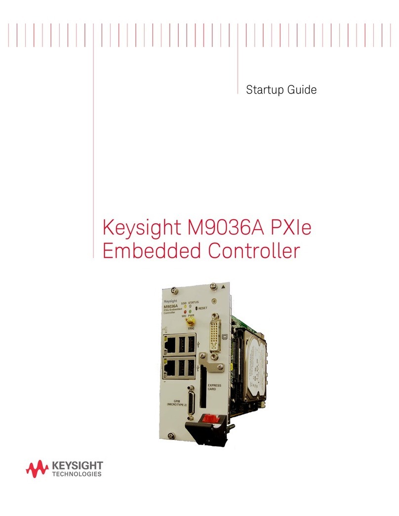
Keysight Technologies M9036A PXIe User guide
Keysight Technologies
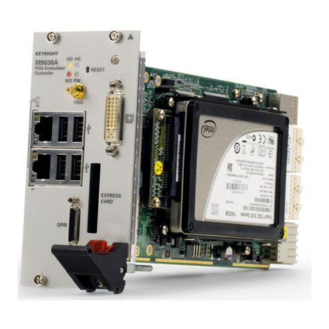
Keysight Technologies M9036A PXIe User manual

Keysight Technologies
Keysight Technologies M9037A General instructions

Keysight Technologies
Keysight Technologies M9037A User guide
Keysight Technologies
Keysight Technologies N1002A User manual
Keysight Technologies
Keysight Technologies N5261A Manual
Keysight Technologies
Keysight Technologies M9038A User guide

Keysight Technologies
Keysight Technologies M9036A PXIe User manual
Keysight Technologies
Keysight Technologies M9035A User guide
Keysight Technologies
Keysight Technologies M9036A PXIe Quick start guide
