Tractive Pentruder MD1 User manual

Operator’s manual for
Pentruder® MD1 Modular Drilling System
with HF-motor and Pentpak® HF-power pack
Version: 1.3 Date: 2012-09-27
Support & Service document
Original instructions
Copyright © 2012 Tractive AB.
Pentruder and Pentpak are registered trademarks belonging to Tractive AB.
Contents
1Introduction................................................................................................................2
2Description of the machine .........................................................................................3
2.1 Features................................................................................................................................ 3
2.2 Modules MD1 ....................................................................................................................... 3
2.3 Main drive HF-motor and adapter HFMR-MG41..................................................................... 4
2.4 Rig for MD1 drilling machine with 70 mm column system ...................................................... 5
2.5 Rig for MD1 HF-drilling machine with saw track (MCCS) ......................................................... 8
3Safety instructions .................................................................................................... 11
3.1 Safety instructions which are used in this operator’s manual ................................................11
3.2 Intended use of the drilling machine.....................................................................................11
3.3 Not intended use of the drill rig............................................................................................11
3.4 General safety instructions...................................................................................................12
3.5 Safety precautions at site .....................................................................................................13
4Getting started ......................................................................................................... 15
4.1 Overview Pentruder MD1 with 70 mm column system..........................................................15
4.2 Overview Pentruder MD1 with TS track (MCCS) ....................................................................16
4.3 Equipment needed for drilling ..............................................................................................17
4.4 Mounting of drill stand 70 mm column system......................................................................18
4.5 Standard mounting sequence of MCCS drill stand .................................................................21
4.6 Mounting of MD1 modules...................................................................................................25
4.7 HF-motor 15, 18 and 22 kW..................................................................................................28
4.8 Drill bit ................................................................................................................................29
5Pentpak HF-power pack............................................................................................ 30
5.2 Remote control unit.............................................................................................................36
6Drilling ..................................................................................................................... 38
6.1 Preparations before commencing work. ...............................................................................38
6.2 Starting the Pentruder MD1 HF-drilling machine...................................................................39
7MAINTENANCE ......................................................................................................... 42
8Technical Data.......................................................................................................... 43
Pentruder MD1 –Modular HF-Drilling Machine ...............................................................................43
Declaration of conformity ...................................................................................................... 47
Declaration of conformity ...................................................................................................... 48
Operator’s manual for the Pentruder MD1 HF-drilling machine and Pentpak - Original instructions Page 2
1 Introduction
Thank you very much for your confidence in our product! You have chosen to invest in a product which will
give you many years of efficient and profitable production. The Pentruder Modular Drill System has been
developed based on 25 years of experience in this specialized field. With correct handling it offers
outstanding performance, safety and reliability.
It is essential that all personnel working with or in close proximity to the drilling machine have read and
understood the contents of this manual before commencing operations. By reading and understanding the
manual the operator will be able to take advantage of the many features and benefits of the Pentruder
Modular Drill System. Should questions arise, please contact our sales agent.
We are confident that your investment in this equipment and its many design features will enhance your
business competitive edge and profitability!
Product:
Pentruder® MD1 Modular Drill Machine with HF-motor and Pentpak® HF-power pack
There are two choices for the drill stand, namely the 70 mm column system and the Pentruder Modular
Concrete Cutting System (MCCS) based on the saw track.
Manufacturer:
Tractive AB
Gjutargatan 54
S-781 70 Borlänge
Sweden
Phone: +46 243 - 22 11 55, Fax: +46 243 - 22 11 80
Operator’s manual for the Pentruder MD1 HF-drilling machine and Pentpak - Original instructions Page 3
2 Description of the machine
2.1 Features
The Pentruder Modular Drill System MD1 is a versatile and powerful drilling system. The 4-speed MG41
gearbox gives the system a very smooth and efficient run and with two exchangeable spindle units it offers
a wide speed range for different sizes of drill bits.
Quick disconnect couplings reduce the set up time. Small and big drill bits can be drilled in a shorter time
than anyone thought possible.
Pentruder MD1 drill system can be driven by a 15, 18 or 22 kW HF-motor. Together with the MG41
gearbox and a ST2 or ST3 spindle unit and a Pentpak HF-power packs up to 1200 mm big holes can be
drilled easily and efficiently.
Pentruder MD1 HF-drilling machine can either be built on the wall saw track (MCCS) or on the 70 mm
column system.
2.2 Modules MD1
•MG41 4-speed gearbox
•ST2 / ST3 (QDC-)Spindle unit for MG41 (quick disconnect coupling for drill bit optional)
•ERMD1 Extension Adapter for MD1 (Extends capacity by Ø 190 mm per adapter and up to 3
pcs can be used.)
MG41 ST2/ST3 ERMD1
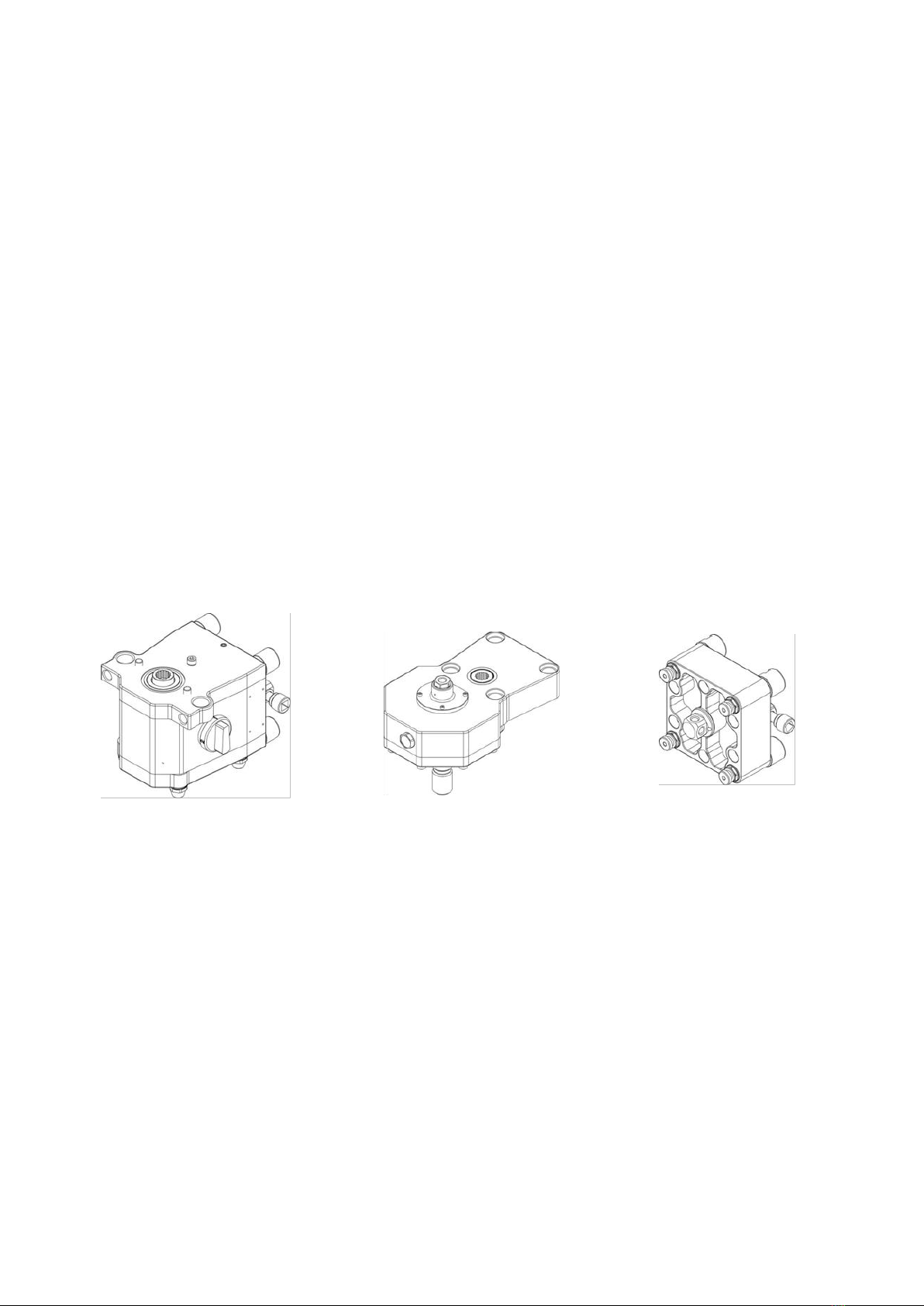
2.2.1 MG41 Gearbox
The Pentruder drill system has a 4-speed gearbox to offer a wide speed range for various drill bit
diameters. Performance and safety is increased as the spindle speed cannot be increased over the
adjusted speed during drilling.
2.2.2 ST2 / ST3 (QDC-)Spindle unit
The concept with exchangeable spindle units makes it possible to get a very wide spindle speed range with
only one drilling machine. The ST2 spindle unit gives lower spindle speeds than the ST3 spindle unit. See
chart on page 27 for spindle speeds. The spindle units can be ordered with or without Quick Disconnect
Coupling (QDC) for the drill bit.
2.2.3 ERMD1 Extension adapter MD1
When drilling big diameter holes over Ø 600 mm (23.6”) an extension adapter must be used to extend the
distance between drill column and spindle, giving more clearance for bigger diameter drills. Each adapter

Operator’s manual for the Pentruder MD1 HF-drilling machine and Pentpak - Original instructions Page 4
extends the drill unit 90 mm (3.5”) further away from the column, i.e. gives additional clearance for a 180
mm (7”) bigger drill bit. Up to 3 pcs can be used together.
2.3 Main drive HF-motor and adapter HFMR-MG41
•HFR415, 15 kW HF-motor, 400 V
•HFR418, 18 kW HF-motor, 400 V
•HFR422, 22 kW HF-motor, 400 V
•HFMR-MG41 Adapter for HF-motor on MG41
The same HF-Motor as is used for drilling is also used for wire sawing and wall sawing. We especially
recommend the 15 and 18 kW HF-motors for drilling.
HFR415 HFR418, HFR422
HFMR-MG41
Operator’s manual for the Pentruder MD1 HF-drilling machine and Pentpak - Original instructions Page 5
2.4 Rig for MD1 drilling machine with 70 mm column system
2.4.1 Standard modules for electric MD1 drill rig with 70 mm column system
•BE1 Base plate fixed / BE2 adjustable quick disconnect coupling
•BETC Base plate w top mount fixed quick disconnect coupling
•CN Columns F/M-70 Female / Male coupling, extendable, 0.5 / 1.2 / 1.5 m
•CN Columns F/J-70 Female / Jack screw, 0.5 / 1.2 / 1.5 m
•CN Column Female / plastic cap, 2 m (only extendable at the bottom)
•ET70 Eccentric bolt for TTFF and JTFF/JTFM tracks
•RST-CN-M Rear support for 70 mm column with male coupling, 2.1-3.2 m
•RST-CN-U Rear support for 70 mm column universal, fastened directly on the column,
2.1-3.2 m
•CE1 Carriage for 70 mm columns
•PT-MD1 electric feed unit
•FE1 Friction clutch
•Connector w. ID-chip for MD1 70mm (if the HF MD1 is used without PT-MD1 electric feed
unit)
2.4.2 Base plates for CN columns and TTFF/JTFF tracks
The BE1, BE2 and BETC base plates are used with CN columns, TTFF or JTFF tracks.
On BE2 the conical quick coupling can be swivelled sideways in increments of 5° for angular drilling
operations. The conical quick coupling on BE1 is fixed. The base plate BETC has a top mount fixed conical
quick coupling.
The columns fitted on the conical quick release coupling can be swivelled around its own axis, and great
flexibility is offered to simplify set-up.
BE1 BE2 with swiveled column coupling BETC

Operator’s manual for the Pentruder MD1 HF-drilling machine and Pentpak - Original instructions Page 6
2.4.3 CN Columns
There are three types of 70 mm columns. Extendable columns CN F/M-70 with a female / male
configuration, meaning that each column is fitted with a female conical quick release coupling at one end,
and a male coupling at the other end.
Columns CN F/J-70 with a Jack Screw in one end, where the male coupling sits on an extendable column,
are used to jack the machine against ceiling or wall.
There is also a column CN-3P8 with a female coupling in one end and a blanking plug in the other end.
This column is 2.0 meters and mostly used for the Pentruder 3P8 wire saw.
The CN F/M and CN F/J columns are available in three lengths, 0.5 m, 1.2 m and 1.5 m.
CN 0.5 F/M, CN1.2 F/M, CN1.5 F/M, CN 2.0-3P8, CN 0.5 F/J, CN 1.2 F/J, CN 1.5 F/J
Operator’s manual for the Pentruder MD1 HF-drilling machine and Pentpak - Original instructions Page 7
2.4.4 RST-CN Rear support
There are two rear supports for the CN-columns. The RST-CN-M is fastened on the male cone at the top of
the column. The RST-CN-U is fastened directly on the column and can be fitted on any side of the column
as there are two openings for the rack and the clamp can be turned upside down as well. The rear supports
are 2.1 meter long when fully pushed in and can be pulled out to a length of 3.2 meters.
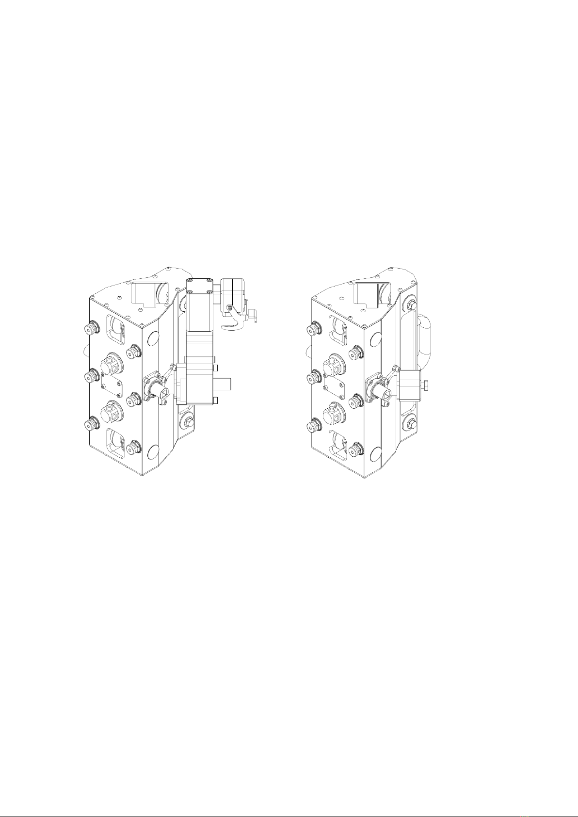
2.4.5 CE1 carriage and PT-MD1 automatic feed unit / FE1 Friction clutch
The MD1 HF-drilling machine can be used with or without automatic feed unit. If the automatic feed unit is
not used, there is a friction clutch instead, to prevent the carriage from sliding on the column. The CE1 can
be fed manually, even if the automatic feed unit is fitted.
Please note that when the MD1 has no automatic feed unit a blind plug is needed to activate the software
in the Pentpak which controls the HF-motor.
CE1 with PT-MD1 automatic feed unit CE1 with FE1 Friction clutch
2.4.6 Pivoting head
•PD1/PD2 Pivoting head
An universal pivoting head can be used to simplify set-up in many cases. The Pivoting Head can for
example be fitted on a vertical column and a horizontal column fitted to the Pivoting Head conical quick
coupling.
The column quick coupling is of the same type as on Base Plate BE2, with a swiveling face tooth coupling
allowing for adjustment of drill angle in 5° increments.
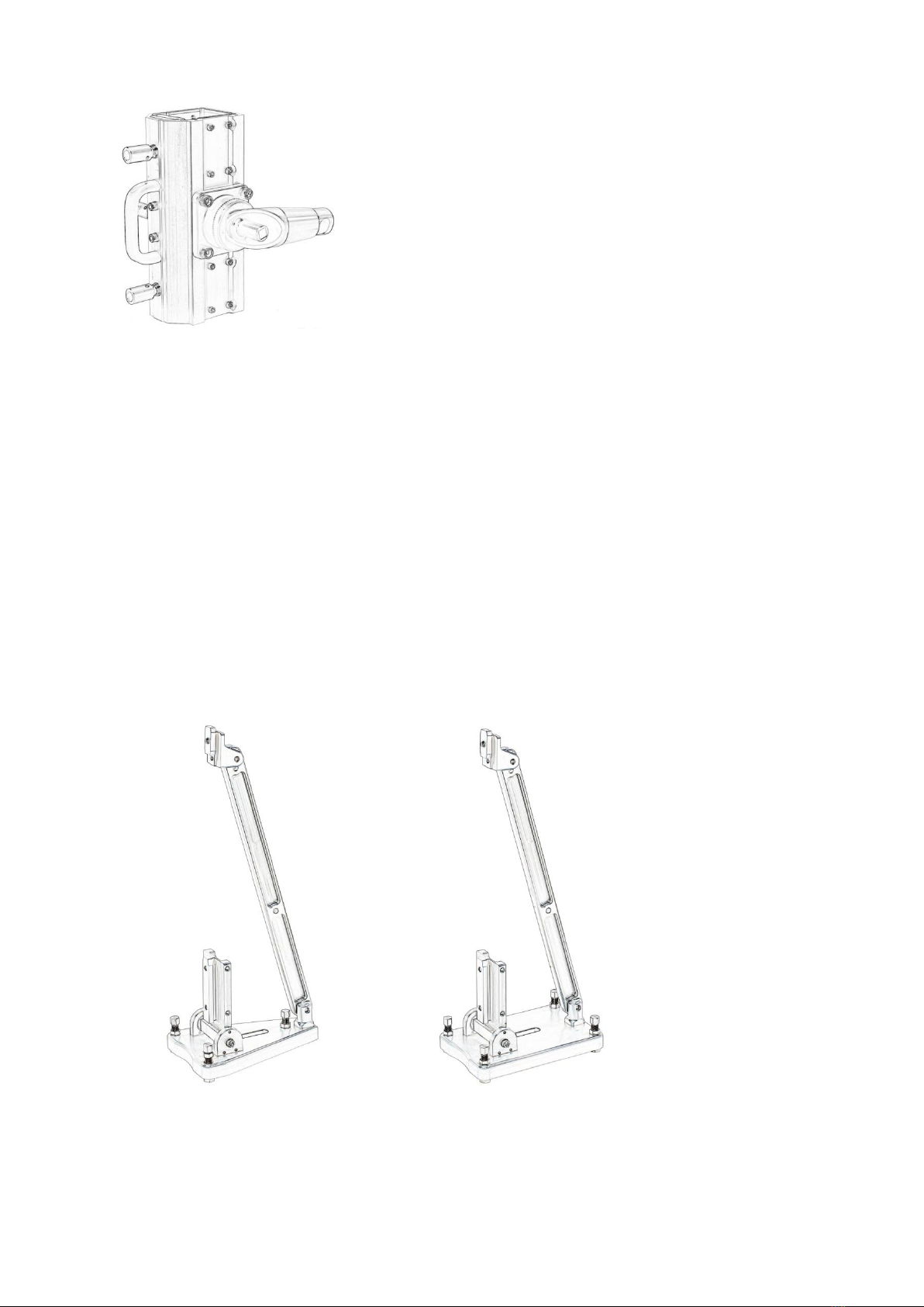
Operator’s manual for the Pentruder MD1 HF-drilling machine and Pentpak - Original instructions Page 8
PD1/PD2
2.5 Rig for MD1 HF-drilling machine with saw track (MCCS)
2.5.1 Standard modules for MD1 drill rig with saw track (MCCS)
•BTS3 Base plate for TS type tracks, triangular, 220 x 320 mm
•BTS4 Base plate for TS type tracks, rectangular, 220 x 320 mm
•TS T-slot type track, 0.85 / 1.15 / 1.7 / 2.0 / 2.3 / 3.45 m
•RST-TS1 Rear support for TS-track, 2.1-3.2 m
•CEG-E-MD1 Carriage, gliding, MD1 QDC coupling. Automatic feed. Max feed speed 0.8
m/min.
•CEG-M25 Carriage, gliding. Manual feed. Reduction 25:1
•CER-M3-U Carriage, roller type, MD1 QDC coupling. Manual feed, reduction 3:1
•Connector w. ID-chip for MD1 70mm (if the HF MD1 is used without electric feed unit)
•HK-1 Hand crank for CER and CEG carriages
2.5.2 Base plates BTS3/BTS4 - MCCS
Base plate BTS3 and BTS4.
There are two different base plates for the TS track, the BTS3 and BTS4.
The BTS3 with only three leveling screws is not recommended for heavy drilling and for drilling with the drill
spindle turned to one side. It is excellent for light duty drilling and in several other applications where side
loads do not occur.

Operator’s manual for the Pentruder MD1 HF-drilling machine and Pentpak - Original instructions Page 9
2.5.3 TS T-slot type track - MCCS
The Modular Concrete Cutting System (MCCS) builds on the t-slot type track which has been used for the
Pentruder wall saw since 1997. The TS track is very light weight, yet offers great stiffness and stability to
the system.
The TS tracks are available in the lengths 0.85, 1.15, 2, 2.3 and 3.45 m and the weight is 6.95 kg per
meter.
2.5.4 RT-TS1 Rear support
The RT-TS1 rear support is fastened on TS track with a . The RT-CN-U is fastened directly on the column
with a t-slot profile (which also is used together with the track feet for the Pentruder wall saws). The rear
support is 2.1 meter long when fully pushed in and can be pulled out to a length of 3.2 meters.
Operator’s manual for the Pentruder MD1 HF-drilling machine and Pentpak - Original instructions Page 10
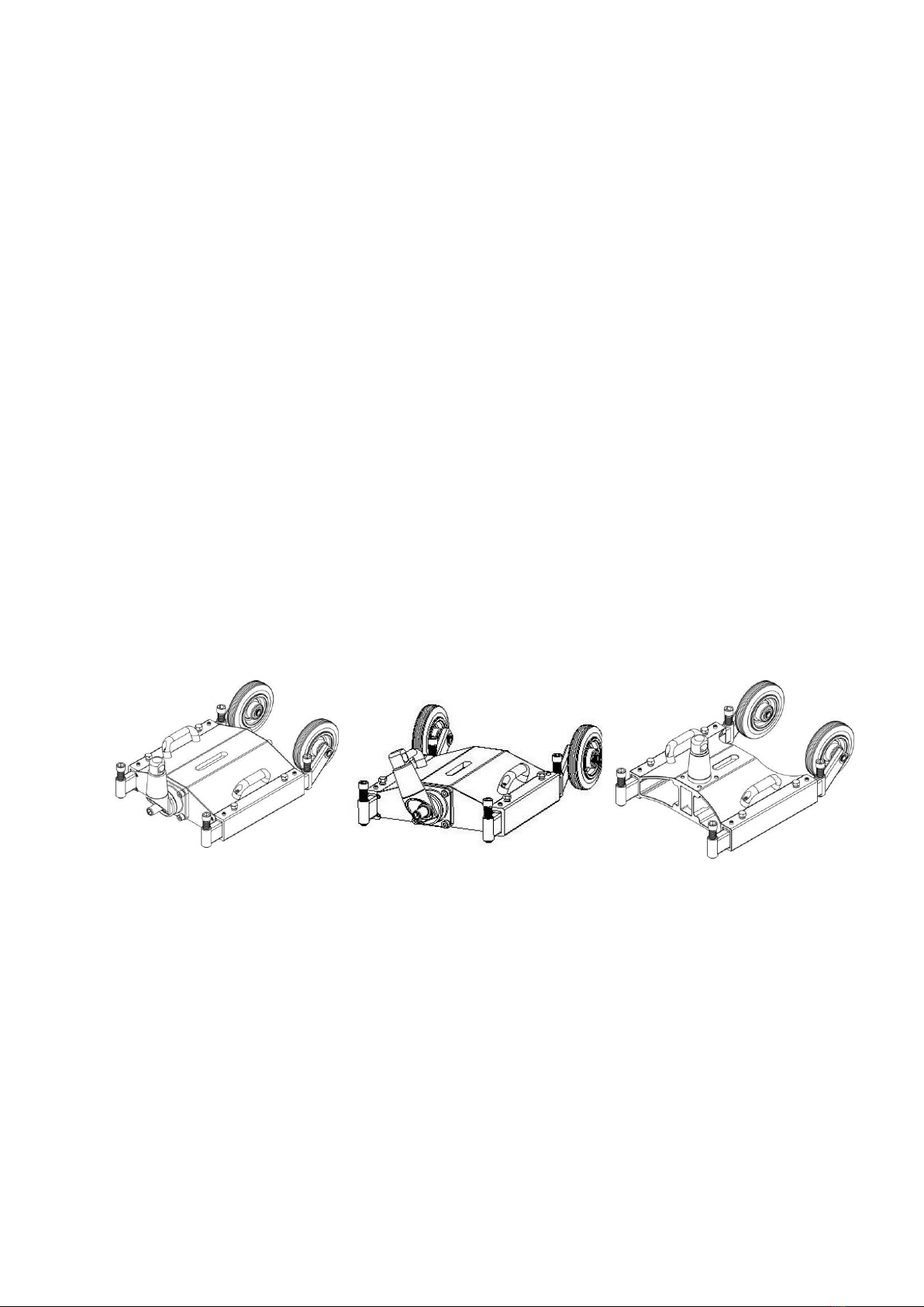
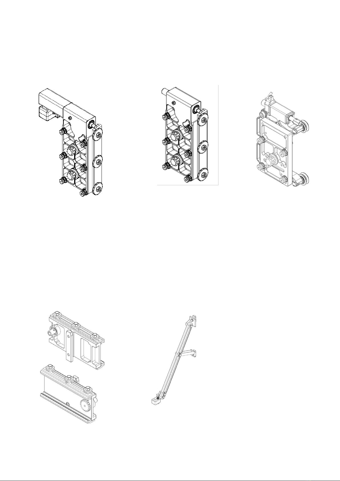
2.5.5 CEG/CER Carriages - MCCS
The MG41 gearbox and ST spindle units can be used either with a CEG gliding carriage or a CER roller
carriage. If automatic feed is required, there is the CEG-E-MD1. Please note that when a carriage without
automatic feed is used, a blind plug is needed to activate the software in the Pentpak which controls the
HF-motor.
CEG-E-MD1 Carriage, Gliding,
with electric feed motor
CEG-M25 with manual feed
CER-M3-MD1 with manual feed
Carriage which glides on the track
with teflon liners.
Electric automatic feed for MD1
high frequency drilling machine.
No manual feed possible.
Total gear ratio 2500:1.
Max feed speed 0.8 m/min
Carriage which glides on the track
with teflon liners.
Manual feed. Lower carriage for 3P8
wire saw. Suitable for heavy drilling
with big drill bits, chain sawing and
more applications to come.
Carriage with tapered rollers like
on the wall saws.
Manual feed.
Coupling for MD1 drilling
machine.
Gear ratio 3:1
Overview CEG and CER carriages for Pentruder MD1 HF-drilling machine
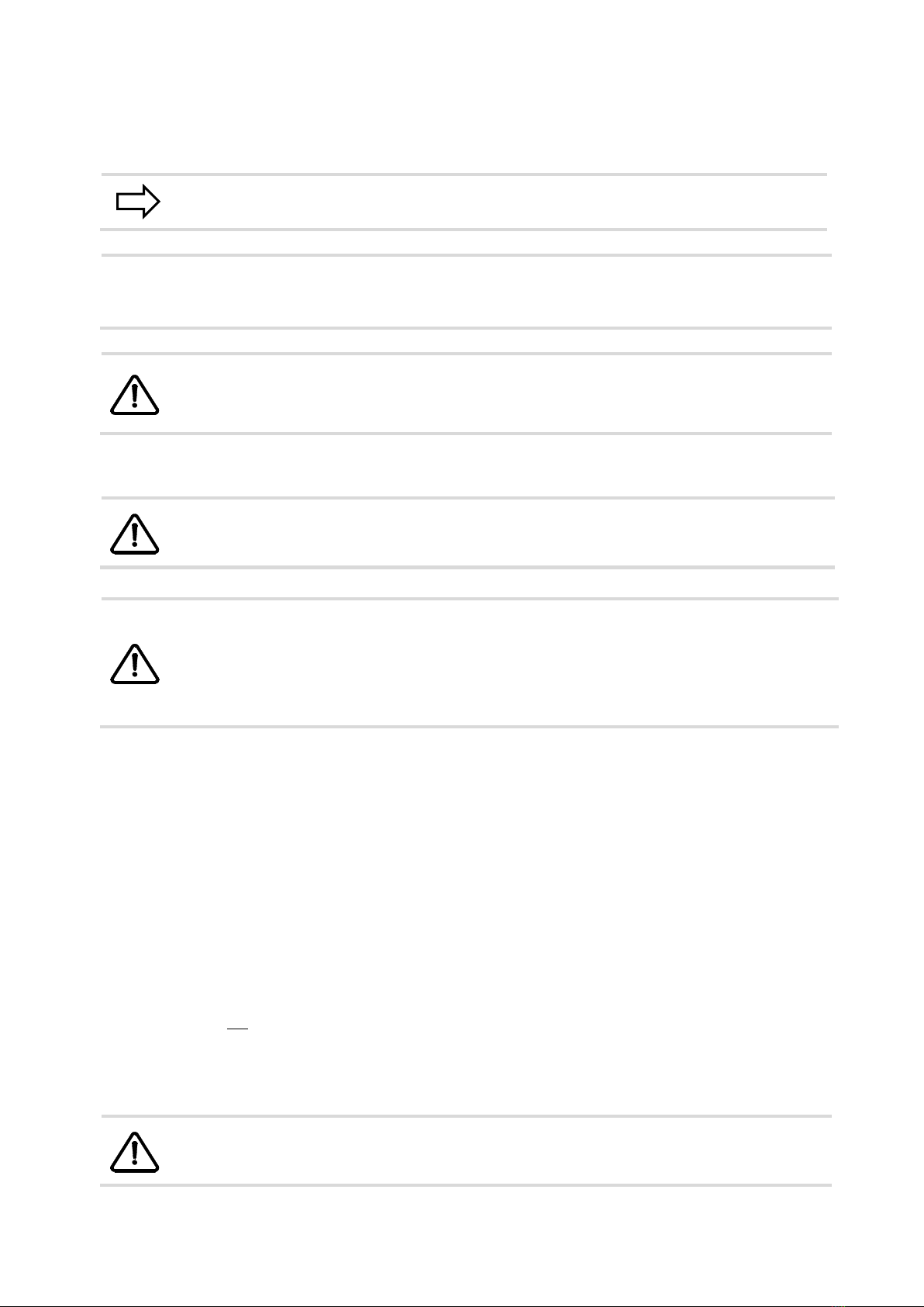
2.5.6 CEL-TS Carriage line and corner drilling
CEL-TS Carriage line and corner drilling CT-CEL Back support for CEL-TS
From two different views.
Operator’s manual for the Pentruder MD1 HF-drilling machine and Pentpak - Original instructions Page 11
3 Safety instructions
3.1 Safety instructions which are used in this operator’s manual
Note!
This sign indicates technical specifics and methods which will facilitate the
job.
!
Important!
Here we inform about risks connected with use of the machine, and, if the
safety precautions are not respected, can result in damage to property and
persons in close proximity to the machine.
WARNING!
In these we inform about risks connected with use of the machine, and, if the
safety precautions are not respected, can result in serious injury and even to
fatal injuries to persons in close proximity to the machine.
3.2 Intended use of the drilling machine
WARNING!
The drilling machine may only be used for core drilling in concrete, masonry
or similar materials. Other use is non intended and therefore to refrain from.
WARNING!
Before drilling is commenced, make sure that;
•There are no power lines, gas or oil pipes in the way.
•The statics of the building are not imperiled because of the drilled holes.
•No damage is done on other side of the wall when drilling through the wall.
Other use is non-intended and therefore to refrain from. For maximum drill bit size, see Technical Data.
This drilling machine may not be used before the operator is fully educated by our sales distributor in
handling the machine. It is the obligation of the buyer to make sure that the operator really has received the
information necessary to operate and take care of the machine in a correct and safe way. Incorrect
handling can lead to serious or even fatal injury to the operator and persons in proximity to the machine.
Tractive AB is not responsible for damage on property or persons whether they originate from incorrect
handling or deficient maintenance or as a consequence from not checking the machine for damage and/or
defects before taking it into use.
The following safety instructions are important to know and follow.
3.3 Not intended use of the drill rig
This drill rig may not be used for:
•any kind of stirring jobs, for instance stirring of paint of similar.
•drilling in soil, for instance drilling holes for poles.
•free hand drilling.
WARNING!
The drill rig may not be used on loose masonry as the anchors may come
loose.

Operator’s manual for the Pentruder MD1 HF-drilling machine and Pentpak - Original instructions Page 12
3.4 General safety instructions
WARNING - DANGER OF LIFE!
It is potentially fatal to drill in a power line which is energized. The drill rig can
get energized.
A circuit breaker doesn’t protect against this danger.
WARNING!
•The drill rig is state of the art and follows the present regulations.
However, incorrect handling of the machine can lead to serious or even
fatal injury to the operator and persons in proximity to the machine.
•To maintain the level of safety inherent in the design of this machine,
only Tractive original spare parts may be fitted. Tractive AB disclaims all
responsibility for damages occurring as a result of use of non-original
parts.
•All persons which are operating or in any way working on the drilling
machine has to read and understand the whole operator’s manual and
especially the safety instructions, before any work is commenced. It is
the obligation of the buyer to make sure that the operator really has
received the information necessary to operate and take care of the
machine in a correct and safe way.
•The drill rig may only be operated and serviced by authorized and
trained personnel. The personnel should be trained by personnel which
is authorized by the manufacturer.
•No work should be commenced which cannot be judged to be safe.
•The operator is obligated to immediately inform about changes on the
drill rig which can impair the safety of the machine.
•The user is liable that the drill rig is in faultless condition and that all
functions are in order before work is commenced.
•Modifications or changes on the drill rig which might impair the safety of
the machine are not allowed.
•Before any kind of service or mounting on the drill rig is commenced, the
drill motor must always be switched off and the 32/63 Amp plug and
cable disconnected from the drill motor.
•Tractive AB is not responsible for damage on property or persons
whether they originate from incorrect handling or deficient maintenance
or as a consequence from not checking the machine for damage and/or
defects before taking it into use.
•Safety regulations at the work place must be followed as well as the
safety regulations of the operator’s manual for the drill motor used.
•The drilling machine may not be used in an environment where
explosion protected equipment is demanded.

Operator’s manual for the Pentruder MD1 HF-drilling machine and Pentpak - Original instructions Page 13
3.5 Safety precautions at site
WARNING!
•Always check that the equipment is in faultless condition and that all
functions are in order before work is commenced.
•No mounting, for instance change of drill bit, may be performed on the
drill rig unless it is disconnected electrically from the mains.
•Safety regulations at the work place must be followed as well as the
safety regulations of the operator’s manual for the drill motor used.
•All persons working with, or in the proximity to the drilling rig should wear
safety equipment, i.e. protection helmet, protection shoes, gloves, eye
and ear protectors. Other safety regulations at the work place must be
followed. The noise level at drilling might lead to permanent hearing
disorders if not ear guards are worn.
•The operator should have good supervision over the drill system and
inform passing persons about possible risks.
•Unauthorized persons shall not be within the risk area (the area around
the drill unit).
•The drill bit may not be touched when the drill motor is in operation.
•Never connect the hydraulic hoses to either drill unit or power pack while
the power pack is running. The power pack must be disconnected from
the power supply by removing the 32 or 63 Amp plug and cable from the
power pack before any connections are made.
•The power pack must always be switched off and the 32/63 Amp plug
and cable disconnected from the power pack before any kind of service
is commenced.
•Mounting and dismounting of the drilling unit and drill bit may only take
place when the drill motor is disconnected from the power pack by
removing the 400V power cable.
•The power pack is water cooled and must be drained from water when
the ambient temperature is in the proximity of or below 0 degrees
Celsius.
•The electric motor of the power pack is water cooled and the water
pressure must therefore be limited to max 5 bar. The incoming water
supply may only be connected to the lower connection on the power
pack. The quick disconnect couplings may not be replaced with
couplings that are not fully open when disconnected.
•Always lift the drill unit ergonomically correct. The Pentpak is not
provided with hooks for lifting. Should this unit need to be lifted with a
crane, this should only be done after permission and instructions have
been given by a person responsible for safety on the site. Contact your
sales agent for instructions on how the lifting can be done in the best
way.
•The base plate must always be securely anchored to perform safe
drilling.
•Never run the drill unit without water cooling. The seals are quickly worn
and water leak can occur. Should the cooling water seize to function,
stop the machine immediately.
•Before drilling is commenced all persons involved must know how the
emergency stop button is working.
•Remember always to cover drilled holes so that no person falls down
and hurts himself.

Operator’s manual for the Pentruder MD1 HF-drilling machine and Pentpak - Original instructions Page 14
•Only connect the power pack to the Pentruder drill system or such
equipment which has been manufactured or approved by Tractive AB.
•Should the drilling machine fall down from the ceiling it could cause
severy injuries. Keep away from the working area of the drilling machine.
•Don’t use any extension or lever to get a higher feeding power.
•A heavy core in a drill bit which rotates outside of the drilled how can
lead to heavy vibrations so that the drilling machine can come loose
from the anchor. Stop the drill bit shortly before it comes out of the drilled
hole.
•Re-bars which have been cut off can be stuck between the core and the
drill bit and block and/or damage the drill bit. Before the drilling is
commenced, make sure that no segments are left in the drilled hole.
•Should the drill bit get stuck, turn off the drill motor and unplug it. Use a
wrench to move the drill bit forwards and backwards until it is
disengaged and can be pulled out of the hole.
•When drilling upwards, make sure the core cannot fall down by securing
it properly. Rope off the working area.
•Only change gear when the main HF-motor is stopped.
•The power pack must only be operated when in an upright position.
•Remember always to cover drilled holes so that no person falls down
and hurts himself.
Operator’s manual for the Pentruder MD1 HF-drilling machine and Pentpak - Original instructions Page 15
4 Getting started
Before drilling with the MD1 drilling machine, it is essential that all personnel working with or in close
proximity to the drill stand have read and understood the contents of this operator’s manual. By reading
and understanding the manual the operator will be able to take advantage of the many features and
benefits of the Pentruder MD1 drilling machine.
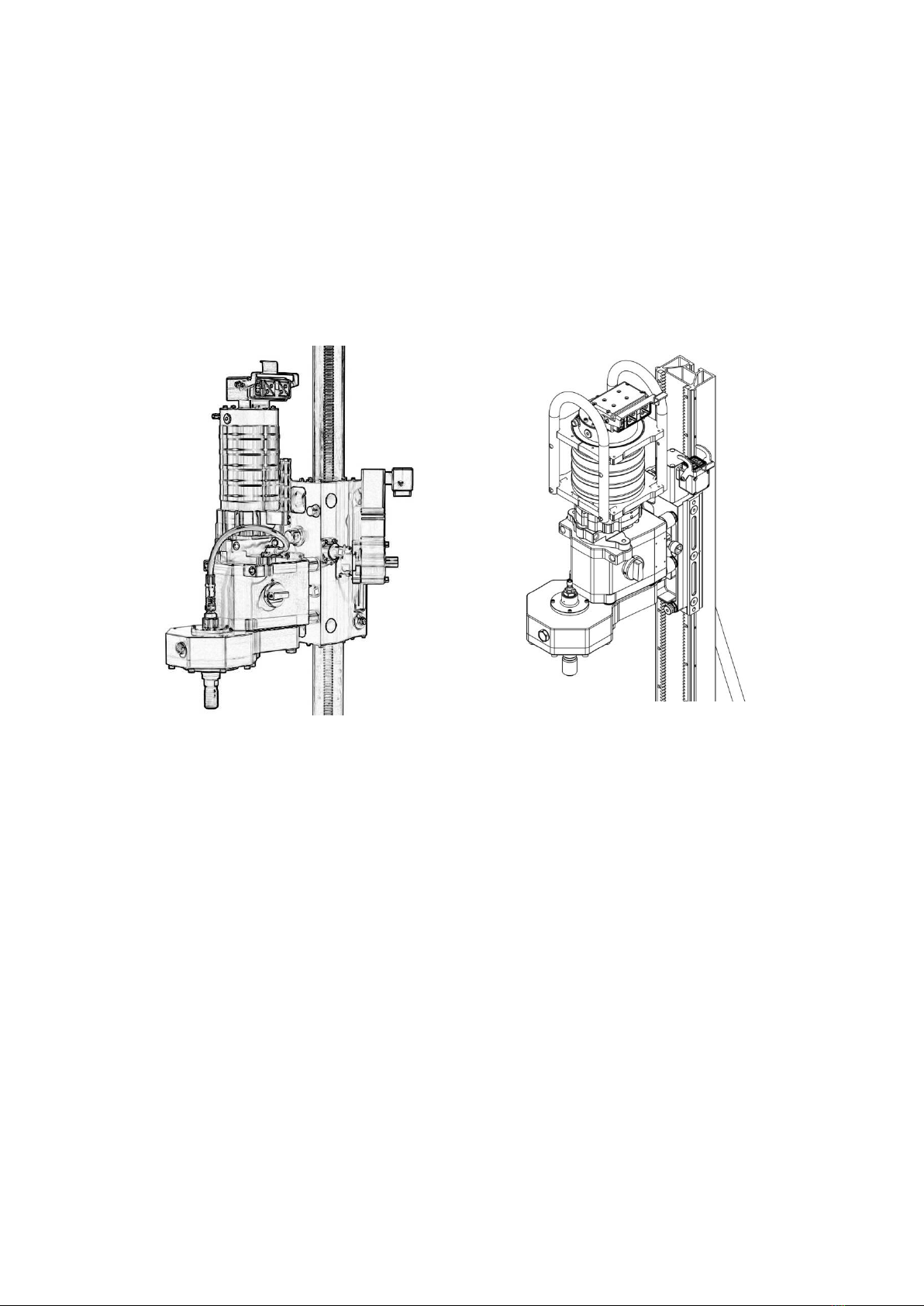
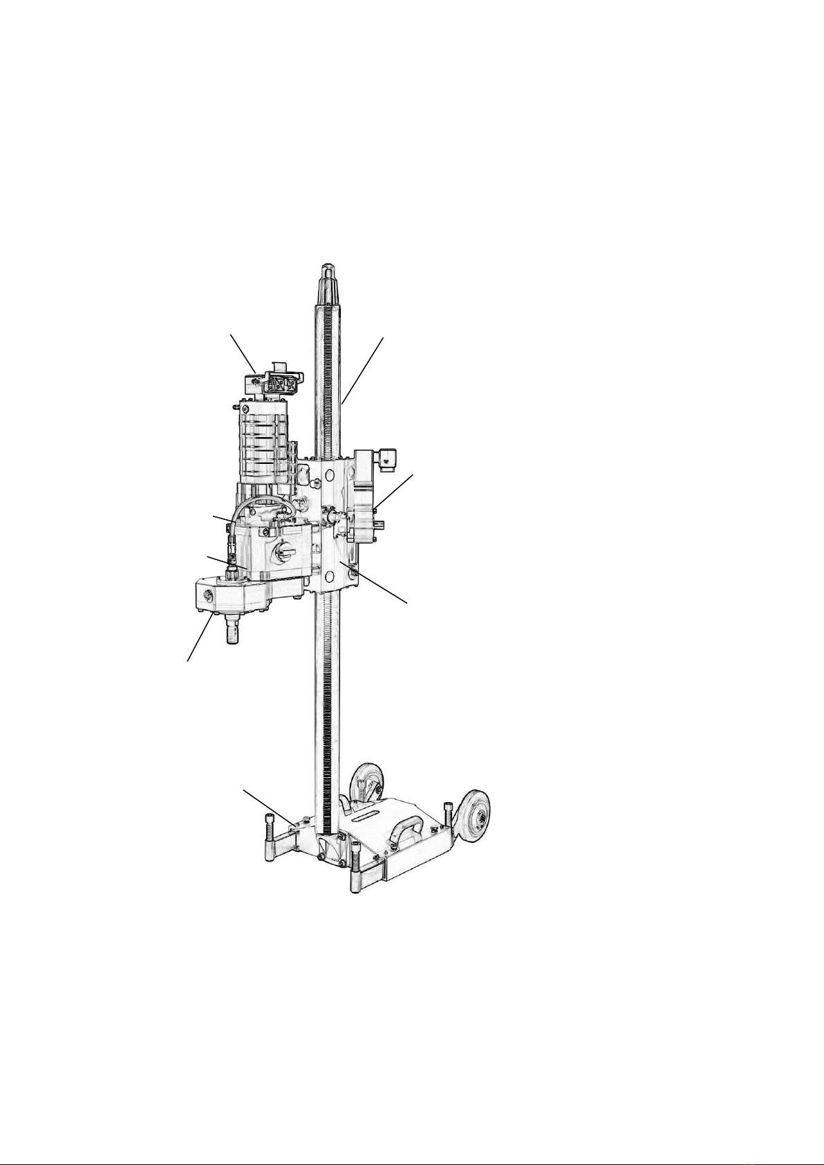
4.1 Overview Pentruder MD1 with 70 mm column system
MD1 HF-drilling machine and 70 mm column system drill stand
15 (18, 22) kW
HF-Motor
Spindle unit
ST2 or ST3
Adapter with slip
clutch
HFMR-MG41
Carriage CE1
Electric feed unit
PT-MD1
Column
(F/M)
Base plate
BE1 / BE2
Gearbox MG41

Operator’s manual for the Pentruder MD1 HF-drilling machine and Pentpak - Original instructions Page 16
4.2 Overview Pentruder MD1 with TS track (MCCS)
MD1 Drill unit and MCCS drill stand.
18/ 22 (15) kW
HF-motor
Spindle unit
ST2 or ST3
(without QDC)
Gearbox MG41
Carriage
CEG-E-MD1
with electric
feed motor
Base plate
BTS3
Adapter with
slip clutch
HFMR-MG41
Track (TS)

Operator’s manual for the Pentruder MD1 HF-drilling machine and Pentpak - Original instructions Page 17
4.3 Equipment needed for drilling
The operator should have the following material at hand:
•Hammer drill: Used to drill holes to secure the base plate.
•Hammer: Securing anchors.
•Anchors and bolts: Mounting the base plate and removal of drilled cores.
•Tools for mounting the drill stand and adjustments: Tool set
•Level: To mount the column correctly at set up and control during drilling.
•Measuring tape: Positioning of base plate in relation to cored hole.
•Extension adapter: Used when drilling big diameter holes to increase the distance between drill
bit and spindle.
•Hoses and electrical plugs: When needed, extension hoses for the power pack and hydraulic
motor can be used.
•Industrial vacuum cleaner: Collection of concrete slurry and water retention.
•Water collector ring: To avoid spreading the water around the drill hole during drilling.
•Equipment for safe removal of drilled cores: Small cores can be removed by hand, big diameter
cores must be removed with a crane or other lifting equipment.
•Helmet, eye- and ear protection, dust guards in dusty environments, protective clothes,
shoes and gloves.
Operator’s manual for the Pentruder MD1 HF-drilling machine and Pentpak - Original instructions Page 18
4.4 Mounting of drill stand 70 mm column system
4.4.1 Assembly of BE base plate- and CN F/M-70 column
Assembly of BE2 base plate- and CN 0.5 F/M-70 column.
1. Secure the base plate to the floor or wall with an expanding anchor and minimum 12 mm (1/2”)
bolt. Be observant on what material the base plate will be mounted on. For safety it is important
that the base plate is properly secured. If mounted on brick or light concrete we recommend to
secure the base plate with through bolts.
2. When drilling with large drill bits we recommend using two anchors of M16 size to fasten the base
plate.
3. Fit the column on the base plate.
4. Pull out the support legs and check with the level to see that the column stands vertical and steady.
If not, adjust with the screws on the support legs until the column stands correctly.
5. To mount the column on the base plate, or a pivoting head, or to join two columns, an eccentric bolt
is inserted in the hole in the column, and tightened clockwise with an ½” knuckle bar or ratchet.
6. The column is locked by turning the eccentric bolt Clockwise.
7. To release the column, the eccentric bolt is turned Counter Clockwise until it lifts from the cone, the
eccentric bolt is removed and the column can be removed.
WARNING!
•The base plate must be securely fastened to perform safe drilling
•Be careful to clean the mounting hole for the base plate with water or air
before fitting an expander bolt.
!
Important!
•Never hit the column into position with a hammer or the like.
Excentric bolt
Male adjustable
conical coupling
4 x adjustable
support legs

Operator’s manual for the Pentruder MD1 HF-drilling machine and Pentpak - Original instructions Page 19
4.4.2 Back support for 70 mm column
For most drill operations a back support is needed to give greater stability, for example when drilling with
high pressure and high load. The back support should always be used to stabilize the column, especially
where circumstances are hard and demanding.
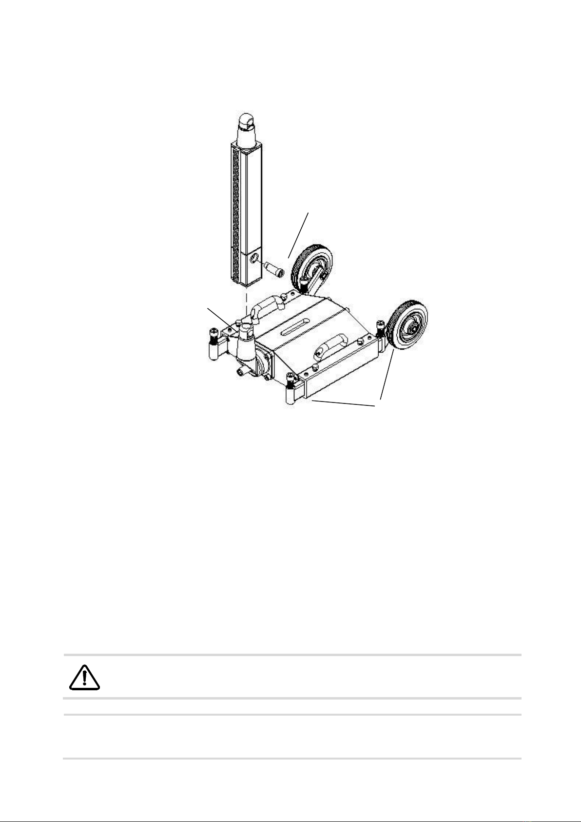
4.4.3 Mounting of carriage CE1 on 70 mm column
CE1-70 carriage with PT feed unit CE1-70 carriage with friction brake
1. Loosen the socket on the hydraulic feed unit or the 19 mm Hex bolt on the friction brake.
2. Put the carriage on the column.
3. Adjust the height of the carriage by turning the feed shaft with a knuckle bar.
4. Tighten the socket on the feed unit or the hex bolt on the friction brake until the carriage doesn’t
slide down the column.
5. For optimum preload of the rollers on the column, the rear rollers should be adjusted using a ½”
spanner and a 15 mm wrench. Adjusted correctly, this eliminates all play between the carriage and
the column. Do not set the rollers too hard. The result will be premature wear of the column.
6. Lock the eccentric shafts for correct pre load of the rollers, by tightening the screw with a 15 mm
wrench.
The drill unit (gearbox, spindle unit and hydraulic motor) can mounted on the carriage with the drill spindle
pointing in both directions along the column. Note that the drill unit can be mounted in two positions along
the carriage.
!
Important!
•Be careful when mounting the carriage on the column. Make sure the
socket / hex bolt is tightened to avoid clamp injuries. Do not overtighten!
½” Feed shaft
6 x Coupling
studs
Nut
2x eccentric
shafts for
adjusting pre
load of the
rollers
19 mm Hex
bolt
Operator’s manual for the Pentruder MD1 HF-drilling machine and Pentpak - Original instructions Page 20
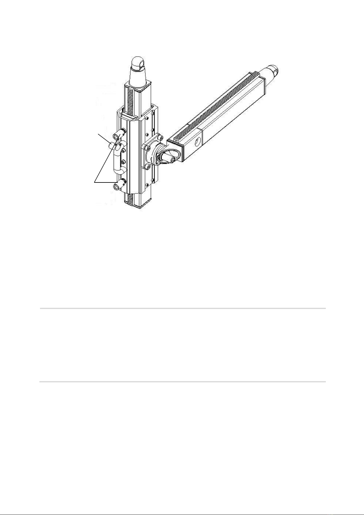
4.4.4 Mounting of pivoting head for 70 mm column
Pivoting head-PD1 with assembled column.
1. Mount the pivoting head on the column.
2. Tighten the locking screws to that the pivoting head doesn’t glide on the column.
3. Use the ratchet to move the pivoting head to the desired position on the column.
4. Lock the pivoting head with the locking screws on the desired height.
5. To mount the column on the pivoting head, an eccentric bolt is inserted in the hole in the column,
and tightened Clockwise with a ½” handle or ratchet.
6. Now you can mount the carriage on the horizontal column, see mounting of carriage CE1 on page
19.
!
Important!
•Be observant so that the eccentric bolt doesn’t slip out of the column
when the column is put on the pivoting head. It MUST be completely
flush with the column side face.
•When the adjustable male-coupling shall be adjusted please make sure
the teeth are correctly in mesh.
•When the pivoting head is mounted, be sure that the locking screws are
tightened to give enough friction between column and pivoting head, to
keep the pivoting head from sliding down the column in an uncontrolled
way.
locking
screw
Feed shaft
Other manuals for Pentruder MD1
1
Table of contents
Other Tractive Drill manuals


