Tractive Pentruder 8-20 HF IQ User manual

Manual for Pentruder 8-20 HF IQ and Pentpak 427 Page 1
Copyright © Tractive AB.
Pentruder and Pentpak are registered trade marks belonging to Tractive AB.
Contents
Introduction .........................................................................................................................................................2
Description of the machine................................................................................................................................3
Saw head Pentruder 8 - 20 HF IQ ..................................................................................................................3
Quick disconnect coupling for mounting of the saw blade (Patent).........................................................5
Tracks and brackets .......................................................................................................................................6
Blade guard .....................................................................................................................................................7
Pentpak 427 high frequency power pack .....................................................................................................8
Design, function and special features of the Pentpak 427. ..........................................................................8
Intended use of the Pentruder 8-20 HF IQ and Pentpak 427.......................................................................9
Safety precautions..........................................................................................................................................9
Getting started ..................................................................................................................................................11
Preparations before commencing work.....................................................................................................11
Preparation and mounting of track feet and tracks ..................................................................................13
Mounting the saw head on the track ..........................................................................................................15
Quick disconnect coupling for HF-motor on saw head............................................................................16
Quick disconnect coupling for the saw blade ...........................................................................................17
Function principle:.......................................................................................................................................17
How to fit a blade on a standard blade flange: ...........................................................................................18
How to fit a blade on a flush cutting flange:................................................................................................18
Peripheral cutting speed and spindle speed .............................................................................................21
Torque and spindle speed in rpm ...............................................................................................................24
Mounting the blade guard............................................................................................................................25
Preparing the power pack............................................................................................................................26
LED type warning lights on the power pack ..............................................................................................29
Remote control unit......................................................................................................................................31
Maintenance ......................................................................................................................................................31
Technical data Pentruder 8 – 20HF.................................................................................................................37
Technical data Pentpak 427 HF power pack..................................................................................................38
Declaration of Conformity................................................................................................................................39
Operators manual for Pentruder
®
8 – 20 HF IQ
Pentpak
®
427 High frequency power pack
Version: 1.0
Support &
Pentruder 8 – 20 Hi Frequency IQ Wall Saw
Service document

Operators manual for the Pentruder 8 – 20HF IQ and Pentpak 427 Page 2
Tractive Support
Introduction
Thank you very much for your confidence in our product! You have chosen to invest in a product
which will give you many years of efficient and profitable production. The Pentruder 8-20 HF IQ has
been developed based on more than 25 years of experience in this specialised field. With correct
handling it offers outstanding performance, safety and reliability.
It is essential that all personnel working with, or in close proximity to, the saw have read and
understood the contents of this manual before commencing operations. Only by reading and
understanding the manual will the operator be able to take advantage of the many features and
benefits of the Pentruder 8 – 20HF IQ. We are confident that your investment in this equipment and
its many design features will enhance your competitive edge and profitability!
The first section of this manual, page 1-2 contains the table of contents and an introduction of the
machine.
The second section of this manual, page 3 - 10, contains a general description of the machine and
explains the different features which make the Pentruder 8-20 HF IQ to one of the safest and most
efficient machines available on the market today.
The third section of this manual, page 11 - 32, contains a description how to get started with the
machine. Please take careful note of the Safety Precautions.
The fourth section of this manual, page 33 - 40, contains instructions how to maintain the
equipment, and technical data.
Important! When you read this manual it is important that you read and understand what is
said about safety under the headlines ”Important”. In those paragraphs beginning with
”Important” we inform about risks connected with use of the machine, and, if the safety
precautions are not respected, can result in damage to property and persons in close proximity
to the machine.
Warning! When you read this manual it is important that you read and understand what is said
about safety under the headlines ”Warning”. In those paragraphs beginning with ”Warning”
we inform about risks connected with use of the machine, and, if the safety precautions are not
respected, can result in serious injury and even to fatal injuries to persons in close proximity to
the machine.
To avoid serious or even fatal injury to the operator and persons in close proximity to the
machine, it is important that the machine always is operated by trained, responsible personnel.
Borttaget:
3 – 9
Borttaget:
10 – 20
Borttaget:
Borttaget:
fifth
Borttaget:
30 – 32

Operators manual for the Pentruder 8 – 20HF IQ and Pentpak 427 Page 3
Tractive Support
Description of the machine
The Pentruder 8 – 20 HF IQ represents a very
modern and safe type of concrete wall saw. The
Pentruder 8-20 HF IQ is developed and
manufactured by Tractive AB in Sweden in a
process where safety awareness, performance and
reliability were the most important design
parameters.
By taking advantage of experience and know-how
built up over many years in this specialised field,
this new design can offer the user great
advantages, for example the markets best
performance to weight ratio.
The Pentruder 8-20 HF IQ offers out-standing
quality. It is the culmination of exacting goals for
quality and safety set at every stage from concept
to finished product.
Saw head Pentruder 8-20 HF IQ
The Pentruder 8 – 20 HF IQ is the most efficient machine for concrete cutting available on the
market today. The design offers many features to make your work safer, easier and more efficient.
•Low weight, only 24kg (54lbs) for the saw head less motor, and 15,5 kg (34 lbs.) for the 27
kW motor. The machine is ideal for cutting with blades from Ø 800 (32”) to 2000 mm (78”)
diameter.
•Lightweight saw head built from aircraft quality components machined from high tensile
strength billet aluminium. No castings are used.
•Quick release coupling for the HF-motor on the saw head. To put the motor on the saw head
or to remove it takes just a few seconds.
•Quick release mechanism of saw head to and from track. Eccentric rollers on the saw head
allow it to be fitted and removed from the track with ease.
•Superior blade mounting system by patented quick release coupling.
•4-speed gearbox for optimum performance. The precision engineered gearbox offers
unsurpassed performance and high efficiency in the transmission. The integrated gearbox
simplifies a correct choice of peripheral cutting speed to match a chosen blade diameter.
•Conical self cleaning track rollers offers optimum control of the saw head along the track.
The rollers are easily adjustable and offer reliable operation over a long period of time. The
guide rollers are arranged in the same plane as the saw blade for optimal force distribution.
Warning! The guard must be fitted whenever
the machine is run.

Operators manual for the Pentruder 8 – 20HF IQ and Pentpak 427 Page 4
Tractive Support
•Oil lubricated speed reduction gearbox in the HF-motor with precision ground helical gears.
•For optimum accessibility the saw arm can be rotated through 360 degrees in either
direction.
•The saw head accepts a 1000 mm (40”) saw blade free from the wall.
•Double motor cooling system, i.e. both rotor and stator are cooled, for sustained reliable
power and high efficiency.
•Efficient water supply to blade central through blade flange, even for flush cutting blades.
•Travel and feed motors are protected within the chassis body. No electric parts except for
connectors are exposed.
•Travel and feed transmission is by means of planetary gear transmission and a self blocking
worm gear transmission. No risk for unexpected movements of the saw head as a result of a
failed electric motor brake.
•The worm screws are supported by oil lubricated axial needle roller bearings and axial thrust
ball bearings.
•The HF-motor has a long life multi plate slip clutch for protection of the gear train if a blade is
jammed. The slip clutch can easily be removed and serviced, or replaced if needed.
•The arm rotation transmission is protected by a multi plate slip clutch if a blade is jammed.
The operator can just “move back” from the cut and start again. Also this slip clutch can
easily be removed and serviced if needed.
•The lower pair of conical rollers are fitted on adjustable eccentric shafts.
Operators manual for the Pentruder 8 – 20HF IQ and Pentpak 427 Page 5
Tractive Support
Quick disconnect coupling for mounting of the saw blade (Patent)
Tractive AB puts great emphasis on creating technical solutions for its products that are safe to use.
This is the most important criteria when our machines are designed.
•The Pentruder 8-20 HF IQ is equipped with a patented quick disconnect coupling for the saw
blade. The intention with this coupling is primarily to enhance safety and handling. A unique
patented coupling for the blade flange enhances safety and simplifies awkward set-up’s
considerably, especially when flush cutting must be performed. The saw blade can always be
fitted after the machine is mounted, radially, and heavy and troublesome set-up’s can be
eliminated to a great extent.
Mounting a saw blade for flush cutting has always been relatively awkward and often one must
mount the saw head and the saw blade together, and it can be difficult to mount also a normal saw
blade for the upper or the lower cut, or even for vertical cuts if the available space is limited.
•With the Pentruder’s quick disconnect coupling all these problems are gone. Provided the
operator is trained in the correct operation of the coupling it will provide considerable
improvement on both safety and efficiency.
Operators manual for the Pentruder 8 – 20HF IQ and Pentpak 427 Page 6
Tractive Support
Tracks and brackets
The tracks and the brackets are designed to provide high levels of rigidity and stability for the lowest
possible weight. The design is unique in the sense that it allows the guide rollers on the saw head to
be aligned above each other, in the same plane as for the cut. This is to provide the highest levels
of safety, stability and precision of cut.
•The tracks are very lightweight at only 6.7 kg / m (4.5 lbs. per foot) track. The stiffness and
stability in the system is still, in spite of the low weight, sufficient for heavy loads and jobs where
up to 2.0 m (78”) diameter blades are used.
•The tracks have stainless steel rails on which the rollers run. They offer high wear resistance and
precise control of the saw head. The grooves into which the guide rails are located have been
machined with great precision.
•The tracks are quickly and easily mounted in an easily accessible yoke by means of a T-slot
piece, which in turn is provided with a lubricated and protected screw and case hardened sleeve-
type nut. The hardened sleeve-type nut safeguards that the screw preload is always adequate to
clamp the track. This system improves safety and reduces the possibility of the nut working loose
because of vibration or variations in load.
•The brackets are versatile and easy to use. A minimum of two brackets are needed to fit one
track. When two tracks are joined, at least three brackets must be used, one of which must be
mounted directly over the joint between the two tracks.

Operators manual for the Pentruder 8 – 20HF IQ and Pentpak 427 Page 7
Tractive Support
Blade guard
The blade guards are made from sheets of hardened aluminium, screwed together with spacers to
achieve strength and stiffness. The blade guards are available in five different sizes, Ø 800 (32”), Ø
1000 (40”), Ø 1200 (48”), Ø 1600 mm (63”) and 2000 mm for normal and flush cutting. The 2000
mm blade guard is used with the parallel guide just as the fully covering blade guards.
Fully covering parallel blade guards in the sizes Ø 600, Ø 800, 1000 and 1200 are available for use
together with a special parallel guide.
•New regulations put new and higher demands on safety, and thereby on the blade guards.
Because of the lightweight design it is more likely that the operator will choose to use the blade
guards on all jobs – this has not always been so! The guards on the Pentruder 8 – 20 HF IQ are
so convenient and lightweight they should always be used. It is a basic requirement for safe
handling of the machine.
•Spray from the saw blade is reduced thanks to the extra swivelling guard piece.
•Automatic control of the blade guard through the movement of the saw arm, the operator need
not adjust the guard manually while the machine is in operation.
•Detachable side pieces. The guards are divided in three pieces with a fixed centre piece and two
detachable side pieces for cutting into adjacent surfaces.

Operators manual for the Pentruder 8 – 20HF IQ and Pentpak 427 Page 8
Tractive Support
Pentpak 427 high frequency power pack
The Pentpak 427 high frequency power pack is designed to a new and unique concept. The
electronic units are especially designed for the Pentpak 427 and the power pack is one of the most
compact designs on the market. It offers outstanding performance combined with reliability, safety
and ease of handling.
New regulations for the design of machines and the specifications for their inherent safety have
been the ruling parameters in the design and development of this power pack.
Design, function and special features of the Pentpak 427.
•For optimum safety and manoeuvrability all functions are controlled through a remote control
unit. The operator can therefore always be in the safest and best possible position and still have
full control of the machine.
•The remote control system contributes to a high level of safety. All functions are reset
automatically when the power supply is disconnected, or when any of the Emergency Stop-
buttons are depressed. The blade, if in rotation, and in a cut, will continue to rotate because of its
inertia, but will coast to a stop after a few seconds. If the blade is rotating and not in a cut, it will
take longer before the blade stops. No functions remain after the power pack has been shut off.
At every restart the power pack starts from the same initial mode with all functions reset.
•The converter is water cooled which provides excellent cooling of the transistor power modules in
the frequency inverter.
•If the power pack is run using an inadequate supply of cooling water, it is still protected from
overheating by means of a temperature sensing device inside the power pack.
•The Pentpak 427 is compact and weighs only 26 kg, still it can drive the electric motor with a
continuous output of 27 kW.
•The power pack has a high overall efficiency factor and at 400 V a 32 Amp delay fuse will be
enough to run the power pack and motor at their maximum rated output. We recommend to use a
40 Amp fuse if possible.
•All electrical and electronic equipment is protected under covers and can not easily be tampered
with. The only device that can be operated is the (green) start and emergency stop buttons.
Borttaget:
25
Borttaget:
40,79 lbs

Operators manual for the Pentruder 8 – 20HF IQ and Pentpak 427 Page 9
Tractive Support
Intended use of the Pentruder 8-20 HF IQ and Pentpak 427.
The Pentruder 8 – 20 HF IQ is intended to be used together with the Pentpak 427 power pack, and
may only be used for cutting of concrete and similar materials. It is our expressed recommendation
that the machine not be used for cutting in any other materials. The Pentruder 8 – 20 HF IQ can not
be used with other types of power packs. If connected to other types of power packs (frequency
inverters) Tractive AB disclaims any responsibility for the product.
Warning! Observe that Tractive’s responsibility as a manufacturer can only be accepted when
the saw head, Pentruder 8 – 20 HF IQ, is used together with power packs, machines and
accessory equipment of Tractive’s manufacture and origin.
The Pentpak 427 is primarily intended to power the Pentruder 8 – 20 HF IQ or other Pentruder HF
wall saws. It can also be used for powering other machines of our manufacture, like the MD1,4-
speed drill gearbox, as well as our wire saws. Please contact your dealer for information. Please
observe that Tractive’s responsibility as a manufacturer only can be accepted when the Pentpak
427 is used together with machines and accessory equipment of Tractive’s manufacture and origin.
Important! Always consult Tractive AB or our representative before any other type of machine
or equipment than the Pentruder 8 – 20 HF IQ is connected to the power pack. Observe that
Tractive’s responsibility as a manufacturer can only be accepted when the saw head Pentruder
8 – 20 HF IQ is used together with power packs, machines and accessory equipment of
Tractive’s manufacture and origin.
Safety precautions
It is of paramount importance that the operator has full knowledge and understanding of the
instructions below:
This wall saw may not be used unless the operator is fully familiar with the contents of this manual
and has been trained in its operation by an authorised distributor of Tractive AB’s products. The
operator is fully responsible for the manner in which the machine is operated. It is the responsibility
of the purchaser that the operator has received the information needed to operate and handle the
machine in a safe a correct way.
Warning! Faulty handling of the machine can expose the operator and / or persons in close
proximity to the machine to danger.
Tractive AB disclaims all responsibility for damages to persons and / or property resulting from use
of the machine, whether they are caused by faulty handling or from damages that have occurred as
a consequence of negligent or faulty maintenance, or as a consequence of failure to check and
control the machine with regard to damages and / or faults.
Warning! A Pentruder wall saw used in the correct way is a safe and efficient tool. If the
machine is used improperly this can expose the operator and other persons staying in the same
area to extreme danger or even risk of fatal injuries.
Warning! Basic safety precautions are that all persons present in the same area or in the same
place as the machine shall wear protective equipment including helmet, safety shoes, gloves,
eye and ear protection, and that all other safety precautions applicable on site are to be
respected.
Borttaget:
Borttaget:

Operators manual for the Pentruder 8 – 20HF IQ and Pentpak 427 Page 10
Tractive Support
Warning! A saw blade rotates at up to 60 m/s peripheral speed, i.e. over 200 km/hour (120
mph). The energy stored in such a blade is considerable, and it is always important that the
machine always is mounted according to the instructions given in this manual, and that the
blade guard always is fitted.
Warning! Always check that the equipment is in faultless condition and that all functions are in
order before work is commenced.
Warning! Never connect the power cord from power pack to the HF motor while the power
pack is switched on. Press at least one of the Emergency Stop buttons before the power cord is
connected to power pack and HF-motor.
Warning! The power pack must always be switched off and the 32 Amp plug and cable
disconnected from the power pack before any kind of service or repair is commenced.
Warning! Mounting and dismounting of the saw head may only take place when the saw head
is disconnected from the power pack by removing the power cord from the saw HF-motor and
the 24V DC cord to the feed and travel motors.
Warning! Mounting and dismounting of the blade guard and saw blade may only take place
when the saw head is disconnected from the power pack by removing the power cord from the
saw HF-motor and the 24V DC cord to the feed and travel motors.
Warning! Track brackets may only be mounted according to the instructions given in this
manual.
Warning! To maintain the level of safety inherent in the design of this machine, only Tractive
original spare parts may be fitted. Tractive AB disclaims all responsibility for damages occurring
as a result of use of non original parts.
Important! The power pack should preferably only be operated when it is put on its back with
the hour meter pointing upwards.
Important! The power pack is water cooled and must be drained from water when the ambient
temperature is in the proximity of or below 0 degrees Celsius. To drain the power pack
completely in sub zero temperatures, switch off the blade motor, disconnect water supply,
switch on water on the remote and blow out all water with compressed air. Alternatively, if no
electric power is available, blow backwards with compressed air in the coupling going to the
saw head. The check valve in the water ON/OFF-valve will then open and the remaining water
in the power pack can then be blown out.
Important! The transistor power modules in the power pack are water cooled and the water
pressure must therefore be limited to max 5 bar. The water supply may only be connected to
the short hose on the water ON/OFF-valve on the power pack. The quick disconnect couplings
may not be replaced with couplings that are not fully open when disconnected.
Important! Connect the power pack only to Pentruder wall saws, Pentruder Wire Saws, drill
motors or any such equipment which has been manufactured or approved by Tractive AB.
Always check with your sales agent that the power pack is suited for the machine it is
connected to.

Operators manual for the Pentruder 8 – 20HF IQ and Pentpak 427 Page 11
Tractive Support
Getting started
Preparations before commencing work.
Certain preparations must be done before starting work.
Cleaning: The machine should be carefully cleaned and all functions checked and
found normal before use of the machine.
Tools: Use only those tools that are intended to be used to
operate the machine: Ratchet ½”, socket 19 mm (3/4”),
Allen-socket 8 mm (5/16”), T-shape 8 mm (5/16”) Allen
key .
Quick disconnects: Check the HF-motor quick disconnect coupling for correct function and
cleanliness. Grease screw threads one per week.
Guide rollers: Check that the guide rollers on the saw head can move freely without too
much friction. A certain amount of friction is always present as the
bearings are double sealed with both rubber and steel scraper seals.
Replace bearings and shields when worn or if rollers don’t run freely.
Remote Control unit: Check the remote control unit for correct function and that the Cannon
connector is clean and undamaged.
Water feed: Check that the machine can be supplied with clean cold water, minimum
4 L / minute (1 GPM).
Water seal on
saw head: In the saw arm, there is a rotating shaft with seals used to feed the water
into the centre of the spindle and further to both sides of the blade flange.
Two seals seal off the water which is fed through the spindle, and further
on through the blade flange to the blade. Just above the coupling clamp
screw there is a small water drain hole.
Important! If water comes out of the Water Drain Hole, (see the maintenance
section for reference) while the water is switched on, this is an indication
that the seals must be replaced. The seals should be checked every day
and the oil in the arm should be checked once a week. If the seals are not
replaced in time, water may enter the saw arm transmission and gearbox,
which may cause the transmission to seize or cause irreparable
damages.
Please see the Maintenance section for instructions on how to replace the
seals.
Power cords: Check that all cords and connectors are undamaged and in faultless
condition.
Borttaget:
If questions arise
that can not be answered by
reading the three first sections
of this manual, there is a word
list in the 4:th section of this
manual which may give
additional information on a
particular issue.
Borttaget:
are

Operators manual for the Pentruder 8 – 20HF IQ and Pentpak 427 Page 12
Tractive Support
Power supply: Check if sufficient power is available on the site. The machine must be
connected to a 380 – 500 V 3-phase supply. The power pack has a 32
Amp 5-pin Euro standard receptacle. At 400 V a 32 Amp delay fuse will
mostly be enough to run the power pack and motor at their maximum
rated output. We recommend to use a 40 Amp fuse if possible.
Safety precautions
on the site: Check with the foreman responsible that all necessary precautions have
been performed before commencing work. Await the approval of the
safety precautions and mounting position of the machine from a
responsible person before work is commenced.
Warning! If there is a possibility that concrete blocks may fall down causing injury or
damage to persons or property then they must be secured before starting work. The risk
area must be roped off and a responsible person left in charge, in a safe place, to prevent
entry of unauthorised persons.
Borttaget:

Operators manual for the Pentruder 8 – 20HF IQ and Pentpak 427 Page 13
Tractive Support
Preparation and mounting of track feet and tracks
Bolts for fastening:The track feet and the tracks should be mounted in such a way that they
can not become detached when the machine is working, or at sudden
changes in load on the anchor bolts.
The track feet are designed to fit the track to the surface the machine will
work on. The feet must be fixed by means of M12 x 60 (1/2” x 2”) screws
of 10.9 quality, or better, using a thick washer and anchors of type HKD
M12 (1/2”) or equivalent. See picture below.
Warning! Hilti no longer recommends the use of their HKD anchors
for fastening wall saw track brackets. Use other reliable anchors of
the HKD type. If the HKD anchors or other high quality expansion
anchors can not be fixed securely, the track feet must be securely fixed
with through bolts and large washers to achieve the required level of
safety.
Positioning of feet: The track feet should preferably be mounted in the position shown in the
picture above. The distance from the edge of the feet to centre of cut is
then 128 mm (5”). The distance from anchor bolt to centre of cut is 200 +-
25 mm (8” +- 1”).
Borttaget:
Positioning of
feet
Operators manual for the Pentruder 8 – 20HF IQ and Pentpak 427 Page 14
Tractive Support
Alternative position
of track feet: In certain circumstances it is impossible to mount the track feet as shown
in the picture below. If the track feet must be mounted differently, this may
affect the stability of the track. If this is the case, more track feet should
be fitted to spread the load and increase stability.
Adjusting the height of
the track feet: The height of the fork can be adjusted totally 12 mm by turning the fork
CW or CCW, to compensate for irregularities on the wall. Please be sure
that the fork is not threaded all the way out before the track is mounted.
Leave at least ½ a turn from the fully out or in position.
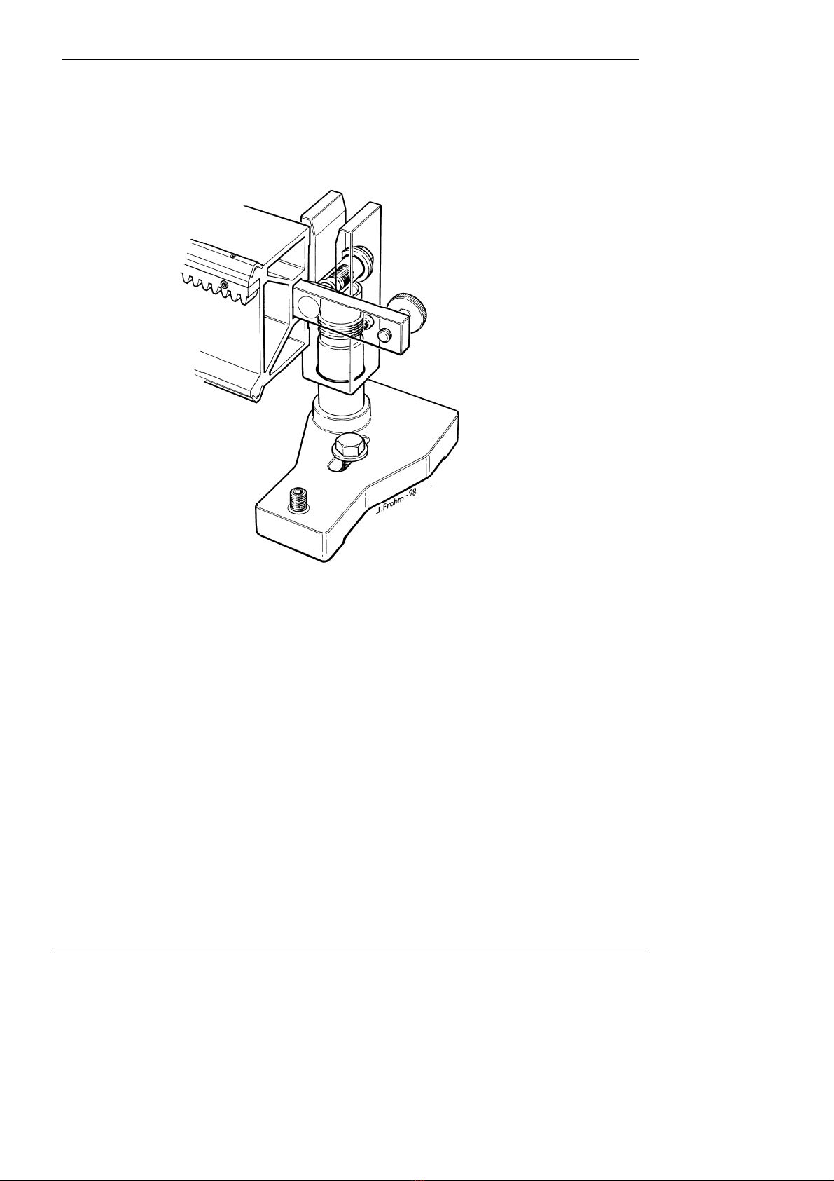
Mounting the track: The track is mounted using clamp screws which fit into the yoke of the
track foot. At least two feet must be used to mount one track.
The clamp screws are fitted in T-slot clamps running in T-slots at the rear
of the tracks. These T-slot clamps can be locked in any position by
means of a knurled knob.
A clamp screw is fitted in to the yoke and should be tightened to 50 Nm
(fairly hard) with a 19 mm (3/4”) spanner.
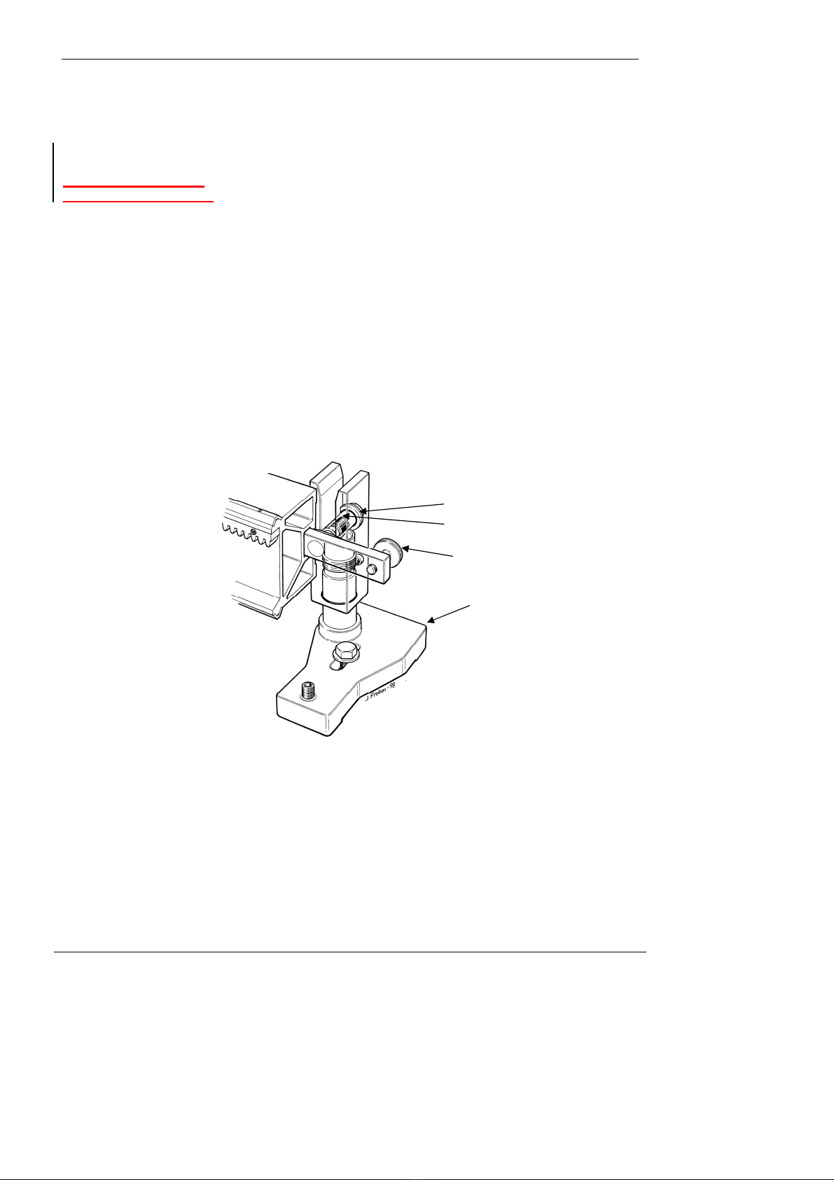
Warning!
Be careful to position the clamp screw in the countersink of the yoke on the track foot. This countersink
Joining two or more
tracks together:
If tracks are to be joined when making long cuts the yoke of the mounting foot should be positioned
Countersink
Clamp screw
Track foot
Knurled knob
Operators manual for the Pentruder 8 – 20HF IQ and Pentpak 427 Page 15
Tractive Support
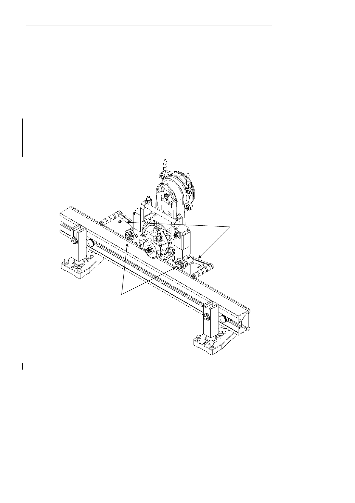
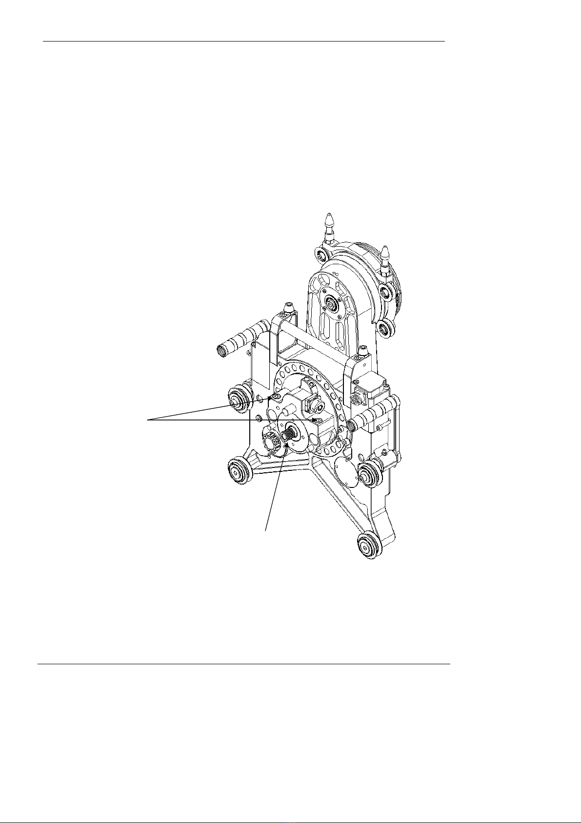
Mounting the saw head on the track
The saw head runs on the track on four conical rollers. The upper rollers are fitted on eccentric
shafts, opened and locked by turning the lifting handles. Fold the saw onto the track, the bottom
rollers engaged first. Then fold the saw head towards the track, to engage the eccentric rollers,
move head slightly along the track to engage the travel gear with the rack, release the locking pins
and turn the handles inwards until the locking pins engage again.
Warning! Before the saw is operated, always check that the eccentric shafts are locked in position
to prevent the saw from falling off the track. Do not turn the handles unless the locking pins are
released.
Locking pins
Eccentric
rollers
Operators manual for the Pentruder 8 – 20HF IQ and Pentpak 427 Page 16
Tractive Support
Quick disconnect coupling for HF-motor on saw head
To reduce the weight of the parts that must be handled by the operator, the saw head is basically
divided in the saw head unit and the drive motor.
The HF-motor is easily fitted on the saw head with a simple and reliable quick coupling. Two clamp
screws hold the HF-motor securely in place while the machine is working. To fit the HF-motor, align
the splined drive shaft and clamp studs with the holes in the saw head, rotate the saw blade very
slowly by hand until the splines fits and motor seats properly. Then tighten the clamp screws using
the 8 mm Allen T-key.
To remove the HF-motor, turn the clamp screws three (3) full turns CCW and pull the motor straight
out from the saw head.
Warning! To avoid any possibility of injuries as a consequence of an unintentionally started HF-
motor, the power cord between the Pentpak 427 and the HF-motor must be disconnected when
the HF-motor is fitted to or removed from the saw head.
Clamp screws
Splined drive shaft

Operators manual for the Pentruder 8 – 20HF IQ and Pentpak 427 Page 17
Tractive Support
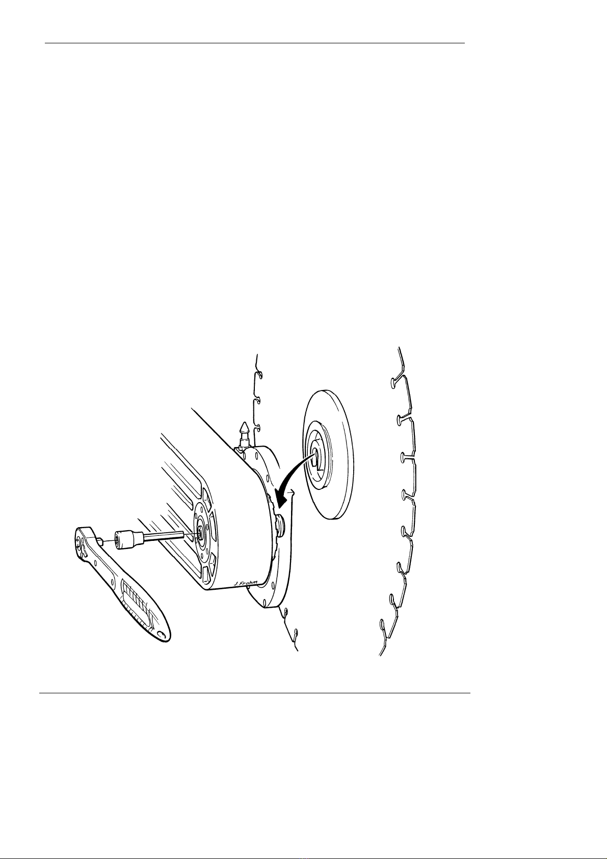
Quick disconnect coupling for the saw blade
Function principle:
The saw blade is fitted on a blade flange by means of an outer collar and clamped by means of a
special centre screw, or, for flush cutting, on a special flush cutting flange by means of 6
countersunk screws and nuts.
The blade flange, regardless of type, is provided with a radial T-slot to the centre of the flange. The
flange, with blade fitted, is mounted on the machine spindle and its pull stud which fits in to the T-
slot in the flange. When the coupling is tightened with the locking screw at the rear of the spindle,
the flange is clamped towards the machine spindle by the pull stud which then moves inwards.
The flange and the spindle are provided with drive dogs to transmit the torque to the blade. The
dogs must always be aligned, in mesh, for the coupling to work properly.
At the same time as the pull stud moves inwards, a conical centering ring moves outwards to centre
the flange on the spindle. This ring at the same time interlocks the coupling by blocking the T-slot.
This principle is very safe, as it does not require more than one single operation to be carried out to
clamp and interlock the coupling. Even if the coupling is not completely tightened the saw blade can
not fall off the spindle as the conical ring keep the blade on the spindle. It is however very important
that the dogs are completely in mesh before the coupling is tightened.
See Warning on next page!
Make sure the dogs are
properly in mesh before
operating the machine!
The screw end should
protrude about 3 mm
when the coupling is
tightened.

Operators manual for the Pentruder 8 – 20HF IQ and Pentpak 427 Page 18
Tractive Support
Warning! Never fit the blade and flange to the saw spindle before first disconnecting two
orange colored power cords from the saw. This important rule must always be strictly followed
to ensure that the blade motor cannot be inadvertently started. Failure to follow this instruction
may result in serious personal injury or death.
The power pack can be placed out of sight of the operator, maybe 30 m’s (90’) away, or on a
different level, and the only way to protect the operator from accidental starting of the blade
motor is for the operator to always disconnect the two orange colour power cords. With the
orange color cords disconnected no power can go to the saw head.
.
Warning! The drive dogs on the machine spindle and blade flange bust be completely
in mesh before the clamping screw is tightened to prevent damage to the coupling.
Failure to follow this instruction may result in serious personal injury or death.
How to fit a blade on a standard blade flange:
Centre bore: The saw blade should have a hole with diameter 60 mm –0 +0.1 mm (1-
3/8” for the U.S. market), and be free from cracks, dents, burrs and dirt.
Transmission of
torque: The friction surfaces of both the flange and the blade must be free from
grease and dirt to be able to securely transmit the torque of the saw blade
motor without slippage. Slippage will cause irreparable damage to the
flanges.
Clamping: The blade is fitted on the inner flange and is clamped by the outer collar
with a special centre bolt. The centre screw should be tightened to 30 - 40
Nm. Grease the centre bolt and thread regularly. The bolt or the female
thread in the blade flange may never start to corrode. Corrosion of the
threads or any part of the bolt may cause failure of the bolt with
catastrophic consequences.
Mounting on the
machine spindle: When the blade is securely clamped on the flange, the blade and flange
assembly is ready to be fitted on to the machine spindle with the quick
coupling.
Warning! The saw blade must always be fitted correctly to avoid danger. The instructions given
above must always be followed to avoid faulty mounting of the blade.
How to fit a blade on a flush cutting flange:
Centre bore: The saw blade should have a hole with diameter 60 mm –0 +0.1 mm (1-
3/8” for the U.S. market), and be free from cracks, dents, burrs and dirt.
Clamping: The blade is fixed with 6 countersunk screws. The bolt circle and size
varies depending on market and supplier of the blade.
Bolt circle: In Europe 110 and 130 mm bolt circle is commonly used with either M10
or M8 screws. For the U.S. market we supply a flange with 4.25 P.C.D.
and 3/8” bolts.
Warning: The Pentruder 8-20 HF IQ is a very powerful machine. This means that the blades
which are fitted for flush cutting must be properly fixed to the machine. When a blade is
fitted to a flush cutting flange, it is very important for safety to respect the following
instructions:
Borttaget:
.
Borttaget:
Britain
Operators manual for the Pentruder 8 – 20HF IQ and Pentpak 427 Page 19
Tractive Support
Screw quality and
torqueing of screws: The blade must be clamped with countersunk screws from Unbrako and
be of quality 10.9. The nuts must be of type “Nyloc” and the fasteners
must be torqued with a torque wrench to 35 Nm for M8 screws and to 50
Nm for M10 and 3/8” screws. The threads must be lubricated with grease
or oil.
Warning! The saw blade must always be fitted correctly to avoid danger. The instructions given
above must always be followed to avoid faulty mounting of the blade, which in turn can cause
serious personal injury or death.
Warning! It is important to be aware of the fact that when a flush cutting blade is used, the
blade is clamped merely by the six countersunk screws, nothing else.
Warning! Flush cutting is a questionable method from a safety point of view. As flush cutting
requires use of a “half” blade guard, the operator should be aware that the level of safety never
can be comparable to normal cutting when a full blade guard is used. This is a potentially
dangerous method and should be treated likewise.
Important! The blade must have a bolt circle where the holes are spaced on an even and exact
pitch to prevent unequal load distribution on the screws, blade and flange. Look out for cracks
around the counter sunk holes in the blade. Some blades are prone to crack and if that
happens, it is potentially a very dangerous situation which can lead to fatal accidents.
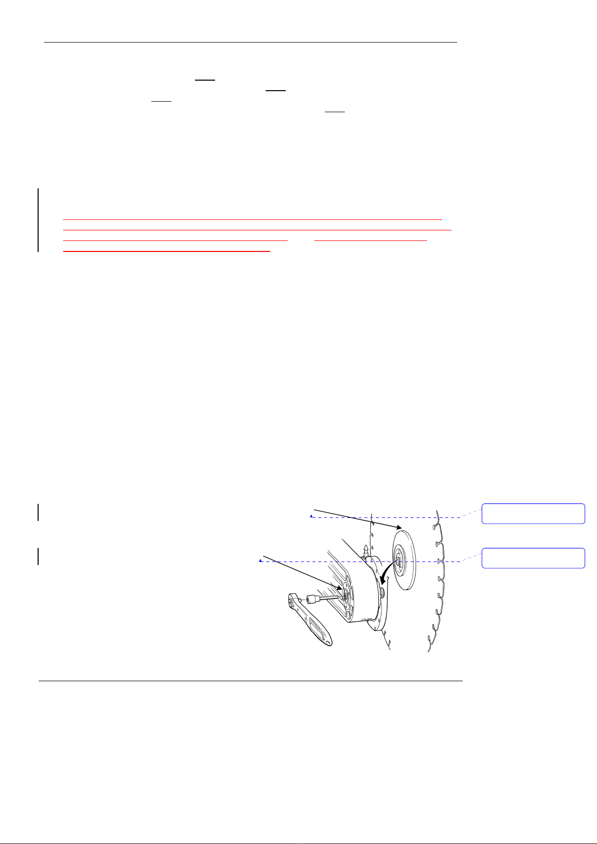
Mounting the blade
with flange on the
machine spindle:
If the procedure described above is followed, the blade and flange are now
ready to be fitted on to the machine spindle with the quick coupling. The blade
flange is provided with a radial T-slot to the centre of the flange. On the
opposite side of the T-slot, there is a groove and this groove should be
positioned upwards when the blade flange is mounted on the saw head
spindle.
Use a ½” ratchet to tighten the clamp bolt on the rear side of the spindle.
Tighten to about 30 Nm. Do not overtighten the coupling clamp screw!
Over tightening the clamp screw may cause irreparable damage to the
coupling and flange.
Warning! Always keep all part of the coupling clean! The safe operation of the
coupling depends on cleanliness of all coupling parts on the machine, and the
blade flange!
Groove
Clamp screw
Formaterat: Teckensnitt:14
pt, Svenska (Sverige)
Formaterat: Teckensnitt:14
pt, Svenska (Sverige)

Operators manual for the Pentruder 8 – 20HF IQ and Pentpak 427 Page 20
Tractive Support
Gearshift - how to select the correct spindle speed:
•Rotate the saw arm to be perpendicular out from the wall.
•The gear selection knob, placed between the HF-motor and the saw head gearbox housing, is
numbered from 1 to 4. Push in the knob by hand or with an 8 mm (5/16”) T-key and turn the
blade slightly back and forth while turning the knob to the required position. Release the button
again to lock the selector knob in position. DO NOT USE A RATCHET TO SHIFT GEARS. THE
GEAR SELECTION MECHANISM MAY THEN BE DAMAGED.
Warning! The gear selection knob may not be operated before first disconnecting the two
power cords from the saw. This important rule must always be strictly followed to ensure that
the blade motor cannot be inadvertently started. Failure to follow this instruction may result in
serious personal injury or death.
The power pack can be placed out of sight of the operator, maybe 30 m’s away, or on a
different level, and the only way to protect the operator from accidental starting of the blade
motor is for the operator to always disconnect the two power cords. With these cords
disconnected no power can go to the saw head.
Borttaget:
H
Borttaget:
,
This manual suits for next models
1
Table of contents
Other Tractive Saw manuals


Popular Saw manuals by other brands


Milwaukee
Milwaukee 6165 Care and operating instructions

Woodstar
Woodstar sl 10d Translation from the original instruction manual

Diamondback
Diamondback 58477 Owner's manual & safety instructions

Würth
Würth master NTS 125 operating instructions

DeWalt
DeWalt DW310 instruction manual

MK Diamond Products
MK Diamond Products TX-3 Operation manual

DeWalt
DeWalt DWS774-lx Original instructions

Craftsman
Craftsman 353.28640 owner's manual

Lissmac
Lissmac COMPACTCUT 501 E operating manual

Jarvis
Jarvis NBS-1 Operation and maintenance instructions

Chicago Electric
Chicago Electric 40315 Owner's manual & safety instructions

Milwaukee
Milwaukee HD28MS Original instructions