Tractive Pentruder 8-20iQ User manual
Operator’s manual
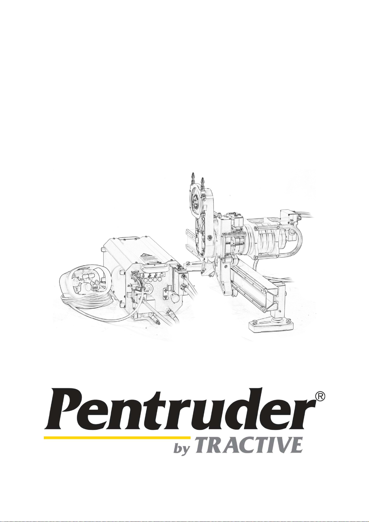
Pentruder® 8-20HF / 8-20iQ HF-wall saw
Pentpak®High frequency power pack

Operator’s manual for Pentruder 8-20HF/iQ and Pentpak HF-power pack – Original instructions Page 1
Operator’s manual for
Pentruder® 8-20HF / 8-20iQ HF-wall saw and
Pentpak®high frequency power pack
Version: 1.5 Date: 2012-03-05
Support & Service document
Original instructions
Copyright © 1997-2012 Tractive AB.
Pentruder and Pentpak are registered trademarks belonging to Tractive AB.
Contents
Introduction.........................................................................................................................................................2
Description of the machine ...............................................................................................................................3
Saw head Pentruder 8-20HF / 8-20iQ............................................................................................................3
Quick disconnect coupling for mounting of the saw blade (Patent).........................................................5
Tracks and brackets.......................................................................................................................................5
Blade guard.....................................................................................................................................................7
Pentpak high frequency (HF-)power pack....................................................................................................8
Design, function and special features of the Pentpak HF-power pack.........................................................8
Intended use of the Pentruder 8-20HF / 8-20iQ and Pentpak HF-power pack............................................9
Safety precautions..........................................................................................................................................9
Getting started..................................................................................................................................................11
Preparations before commencing work.....................................................................................................11
Preparation and mounting of track feet and tracks..................................................................................13
Mounting the saw head on the track ..........................................................................................................15
Quick disconnect coupling for HF-motor on saw head............................................................................16
Quick disconnect coupling for the saw blade...........................................................................................17
Function principle:.......................................................................................................................................17
How to fit a blade on a standard blade flange:...........................................................................................18
How to fit a blade on a flush cutting flange:................................................................................................19
Mounting the blade with flange on the machine spindle.............................................................................20
Peripheral cutting speed and spindle speed.............................................................................................20
How to choose correct gear and cutting speed..........................................................................................21
Torque and spindle speed in rpm...............................................................................................................26
Mounting the blade guard............................................................................................................................27
Preparing the power pack............................................................................................................................28
LED type warning lights on the power pack..............................................................................................31
Remote control unit......................................................................................................................................34
Maintenance......................................................................................................................................................36
Technical data Pentruder 8-20HF / 8-20iQ - HF-wall saw..............................................................................39
Technical data Pentpak HF power pack.........................................................................................................41
Declaration of Conformity ...............................................................................................................................42

Operator’s manual for Pentruder 8-20HF/iQ and Pentpak HF-power pack – Original instructions Page 2
Introduction
Thank you very much for your confidence in our product! You have chosen to invest in a product
which will give you many years of efficient and profitable production. The Pentruder 8-20HF / 8-20iQ
has been developed based on more than 25 years of experience in this specialised field. With
correct handling it offers outstanding performance, safety and reliability.
It is essential that all personnel working with, or in close proximity to, the saw have read and
understood the contents of this manual before commencing operations. Only by reading and
understanding the manual will the operator be able to take advantage of the many features and
benefits of the Pentruder 8-20HF / 8-20iQ. We are confident that your investment in this equipment
and its many design features will enhance your competitive edge and profitability!
The first section of this manual, page 1-2, contains the table of contents and an introduction of the
machine.
The second section of this manual, page 3-10, contains a general description of the machine and
explains the different features which make the Pentruder 8-20HF / 8-20iQ to one of the safest and
most efficient machines available on the market today. Please take careful note of the Safety
Precautions.
The third section of this manual, page 11-35, contains a description how to get started with the
machine. Please take careful note of the Safety Precautions.
The fourth section of this manual, page 36-43, contains instructions how to maintain the
equipment, and technical data.
Important! When you read this manual it is important that you read and understand what is
said about safety under the headlines ”Important”. In those paragraphs beginning with
”Important” we inform about risks connected with use of the machine, and, if the safety
precautions are not respected, can result in damage to property and persons in close proximity
to the machine.
Warning! When you read this manual it is important that you read and understand what is said
about safety under the headlines ”Warning”. In those paragraphs beginning with ”Warning”
we inform about risks connected with use of the machine, and, if the safety precautions are not
respected, can result in serious injury and even to fatal injuries to persons in close proximity to
the machine.
To avoid serious or even fatal injury to the operator and persons in close proximity to the
machine, it is important that the machine always is operated by trained, responsible personnel.
Manufacturer:
Tractive AB
Gjutargatan 54
78170 Borlänge
Sweden
Tel: +46 (0)243 221155
Fax: +46 (0)243 221180
www.tractive.se
Operator’s manual for Pentruder 8-20HF/iQ and Pentpak HF-power pack – Original instructions Page 3
Description of the machine
The Pentruder 8-20HF / 8-20iQ represents a very
modern and safe type of concrete wall saw. The
Pentruder 8-20HF /8-20iQ is developed and
manufactured by Tractive AB in Sweden in a
process where safety awareness, performance
and reliability were the most important design
parameters.
By taking advantage of experience and know-how
built up over many years in this specialised field,
this new design can offer the user great
advantages, for example the markets best
performance to weight ratio.
The Pentruder 8-20HF /8-20iQ offers out-standing quality. It is the culmination of exacting goals for
quality and safety set at every stage from concept
to finished product.
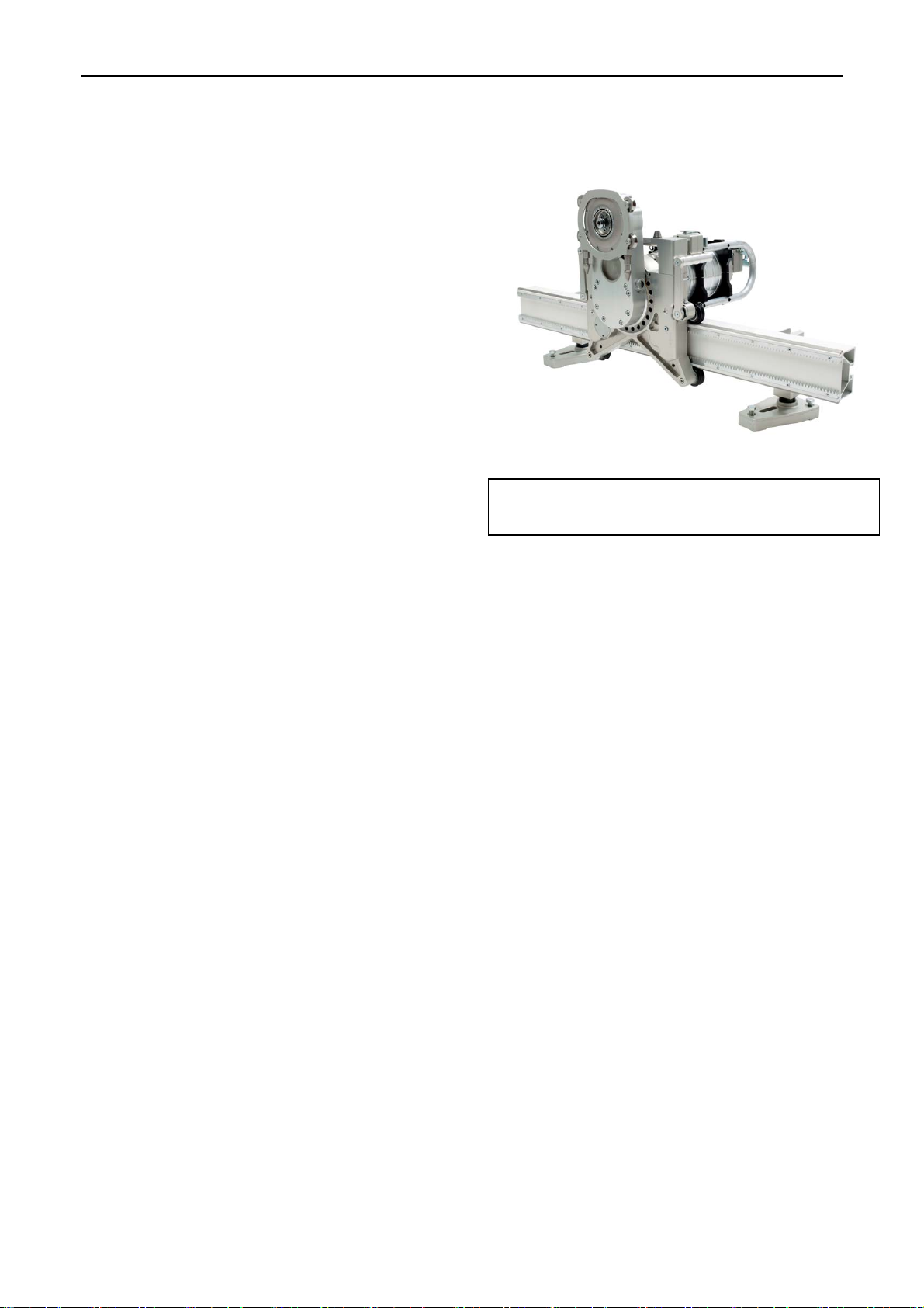
Saw head Pentruder 8-20HF / 8-20iQ
The Pentruder 8-20HF / 8-20iQ is the most efficient machine for concrete cutting available on the
market today. The design offers many features to make your work safer, easier and more efficient.
Low weight, only 24 kg (54 lbs) for the saw head less motor, and 15,5 kg (34 lbs.) for the 22
kW motor. The machine is ideal for cutting with blades from Ø 800 (32”) to 2000 mm (78”)
diameter.
Lightweight saw head built from aircraft quality components machined from high tensile
strength billet aluminium. No castings are used.
Quick release coupling for the HF-motor on the saw head. To put the motor on the saw head
or to remove it takes just a few seconds.
Quick release mechanism of saw head to and from track. Eccentric rollers on the saw head
allow it to be fitted and removed from the track with ease.
Superior blade mounting system by patented quick release coupling.
Conical self cleaning track rollers offers optimum control of the saw head along the track.
The rollers are easily adjustable and offer reliable operation over a long period of time. The
guide rollers are arranged in the same plane as the saw blade for optimal force distribution.
Oil lubricated speed reduction gearbox in the HF-motor with precision ground helical gears.
For optimum accessibility the saw arm can be rotated through 360 degrees in either
direction.
The saw head accepts a 1000 mm (40”) saw blade free from the wall.
Double motor cooling system, i.e. both rotor and stator are cooled, for sustained reliable
power and high efficiency.
Warning! The guard must be fitted whenever
the machine is run.

Operator’s manual for Pentruder 8-20HF/iQ and Pentpak HF-power pack – Original instructions Page 4
Efficient water supply to blade central through blade flange, even for flush cutting blades.
Travel and feed motors are protected within the chassis body. No electric parts except for
connectors are exposed.
Travel and feed transmission is by means of planetary gear transmission and a self blocking
worm gear transmission. No risk for unexpected movements of the saw head as a result of a
failed electric motor brake.
The worm screws are supported by oil lubricated axial needle roller bearings and axial thrust
ball bearings.
The HF-motor has a long life multi plate slip clutch for protection of the gear train if a blade is
jammed. The slip clutch can easily be removed and serviced, or replaced if needed.
The arm rotation transmission is protected by a multi plate slip clutch if a blade is jammed.
The operator can just “move back” from the cut and start again. Also this slip clutch can
easily be removed and serviced if needed.
The lower pair of conical rollers are fitted on adjustable eccentric shafts.
This manual suits for next models
2
Table of contents
Other Tractive Saw manuals


