Tractive Pentruder 3P8 User manual

Operators Manual - High Frequency driven Pentruder 3P8 Wire Saw
Pentruder - Stronger than ever! Applying Standards That Are Years Ahead Of the Competition.
Tractive AB 28 January 2009 Page 1
Copyright © 2008 Tractive AB.
Pentruder is a registered trade mark belonging to Tractive AB.
Contents
Operators Manual for Pentruder®
3P8 Wire Saw Drill System
Version: 2.0
Subject: Pentruder
®
3P8 Wire Saw System
Support & Service
document
Manual Pentruder 3P8 Wire Saw
V2.0.doc
Operators Manual - High Frequency driven Pentruder 3P8 Wire Saw
Pentruder - Stronger than ever! Applying Standards That Are Years Ahead Of the Competition.
Tractive AB 28 January 2009 Page 2
Introduction
Thank you very much for your confidence in our product! You have chosen to invest in a
product which will give you many years of efficient and profitable production. The Pentruder
3P8 Wire Saw System has been developed based on over 30 years of experience in this
specialised field. With correct handling it offers outstanding performance, safety and reliability.
The diamond wire cutting technique has been employed advantageously since many years
especially for jobs where the objects have been difficult to reach to, or too big to be cut with
circular saws, or other methods. Stitch drilling has been popular for many years, but due to its
low overall efficiency, wire cutting has more or less taken over from stitch drilling. With wire
cutting, one is not limited by depth of cut. The technique can be used to make cuts through
huge objects without damaging the adjacent concrete structures. Big sections can be
removed reducing cost for splitting block in several pieces. Wire cutting is a relatively quiet
method, and very little vibration is produced.
It is essential that all personnel working
with or in close proximity to the wire saw
have read and understood the contents of
this manual before commencing operations.
By reading and understanding the manual
the operator will be able to take advantage
of the many features and benefits of the
Pentruder 3P8 Wire Saw System. Should
questions arise, please contact our sales
agent.
We are confident that your investment in
this equipment and its many design
features will enhance your business
competitive edge and profitability!
Product:
3P8 Wire Saw System - High frequency
motor driven.
Power source: directly from Pentpak 418,
422 or 427.
Manufacturer:
Tractive AB
Gjutargatan 54
S-781 70 Borlange
Sweden
Phone: +46 243 - 22 11 55
Fax: +46 243 - 22 11 80
www.tractive.se

Operators Manual - High Frequency driven Pentruder 3P8 Wire Saw
Pentruder - Stronger than ever! Applying Standards That Are Years Ahead Of the Competition.
Tractive AB 28 January 2009 Page 3
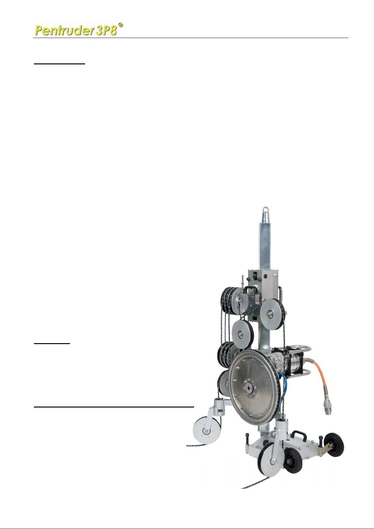
Strong features of the 3P8 wire saw
•The 3P8 wire saw can be driven by either one of the powerful 18, 22 or 27 kW HF-
motors.
•Wire tensioning is fully automatic, with some exceptions. The tensioning of the wire is
governed by software and a microprocessor / digital servo amplifier driven electric feed
motor.
•The main drive pulley has a diameter of Ø 500 mm. It has a rubber drive ring with a
specially designed type of rubber compund giving very good traction wire to rubber,
even when wet. The wire wraps around the main drive pulley over 270°, which gives
superb traction.

Operators Manual - High Frequency driven Pentruder 3P8 Wire Saw
Pentruder - Stronger than ever! Applying Standards That Are Years Ahead Of the Competition.
Tractive AB 28 January 2009 Page 4
Strong features of the 3P8 wire saw, continued
•The cutting speed is continuously variable from 0 to 22 m/second, 4330 sft/min, when
driven by the 18, (25HP) and 22 kW (30HP) motors, and up to 25m/s, 4920 sft/min. for
the 27 kW (37HP) motor.
•The wire magazine stores 8 m of wire per 1 m of stroke of the tensioning carriage (the
upper carriage). The magazine can store (pull in) over 20 m of wire if the total column
length is 3.0 m or more. A combination of 0.5, 1.2, 1.5 and 2.0 m columns ca be used.
•The wire can be run over all wheels on the machine without opening the wire.
•A patent pending system allows the wire to be run also over the adjustable swivelling
wheels, without having to cut the wire.
•All swivelling wheel assemblies can easily be removed from their holders for easy
cleaning and maintenance, by just removing one screw.
•Fully enclosing guards protects the operator(s) and keeps all expensive parts
(reasonably) clean, like the carriages, main pulley drive system, column, etc.
•All pulleys can easily be removed from their mountings. All bearings are sealed with
external seals.
•The main drive pulley is driven by a Gates toothed high torque Carbon cog belt. The
belt transmission is hidden behind guards and protected from concrete slurry. The belt
can be replaced using only a set of standard 6, 8 and 14 mm Allen keys.
•The magazine and idler wheels are Ø 198 mm O.D., 7,8” and the wire is running on
"pitch" Ø 180, 7.1”.
•The magazine and idler wheels have a rubber rings with a specially designed type of
rubber compund giving very good wear resistance. There are totally eleven such
wheels on the 3P8, including six wheels in the magazine.
•All pulleys are a two piece design, and are bolted together. All rubber liners (rings) can
easily be replaced using standard tools.
•When the rubber liners / rings are new, the groove width for the wire, in all wheels, is
10 mm, 0,3930”, meaning that it's suitable for a Ø 11 mm, 7/16” wire. Ø 8 mm, 5/16”
wire also works well.

Operators Manual - High Frequency driven Pentruder 3P8 Wire Saw
Pentruder - Stronger than ever! Applying Standards That Are Years Ahead Of the Competition.
Tractive AB 28 January 2009 Page 5
Strong features of the 3P8 wire saw, continued
•Normally, corners will NOT have to be broken off or chamfered before commencing a
cut. Maximum torque is available from 0 motor speed, and the wire can be started
smoothly. Note, a new wire with sharp bead edges is much harder to start over sharp
corners than only an ever so slightly used wire. With a new wire, it may be necessary
to chamfer edges on the object to be cut.
•The 3P8’s design allows for direct cuts to be made, and satellite wheels can mostly be
omitted. A direct cut means that the machine is fitted directly on the object to be cut, or
very close to it, eliminating the need for extra sattelite wheels.
•Due to the high tractive force of the drive system, even big cuts can be done without
need for sattelite wheels that lifts the wire off from the cut object. The 3P8 is powerful
enough to pull the wire with sufficient force also when the wire is contact with the cut
object over a long distance.
•Most makes and types of sintered wire works well, but electroplated wires can not be
used on the 3P8. This type of wire can be destroyed in just a few minutes if attempted
to be used on the 3P8.
•Normal results in concrete, using a wire that is well adapted to the high power of the
3P8 wire saw:
•Expect to cut between 3 – 6 m² 32 – 64 sq ft per hour is reinforced concrete containing
“normal” aggregate.
•Expect to cut between 1.5 – 3 m², 16 – 32 sq ft per hour is reinforced concrete
containing flint or river gravel aggregate.
•Lifetime of wire: 1.5 – 3 m² / meter of wire, 5 to 10 sq ft per linear ft of wire.
•depending on type of aggregate, content of steel, cutting speed, and quality of wire.
•Lifetime of bearings and rubber rings in magazine and idler rollers: 200 – 400 m², 2200
– 4400 sq ft. The magazine rollers closest to the main drive pulley are the ones that is
exposed to the highest stress, and will need replacement of rubber rings more
frequiently than all other rollers.
•Lifetime of cog belt: 200 - 400 m², 2200 – 4400 sq ft
•Lifetime of cog belt pulleys: 200 - 600 m², 2200 – 6600 sq ft.
Operators Manual - High Frequency driven Pentruder 3P8 Wire Saw
Pentruder - Stronger than ever! Applying Standards That Are Years Ahead Of the Competition.
Tractive AB 28 January 2009 Page 6
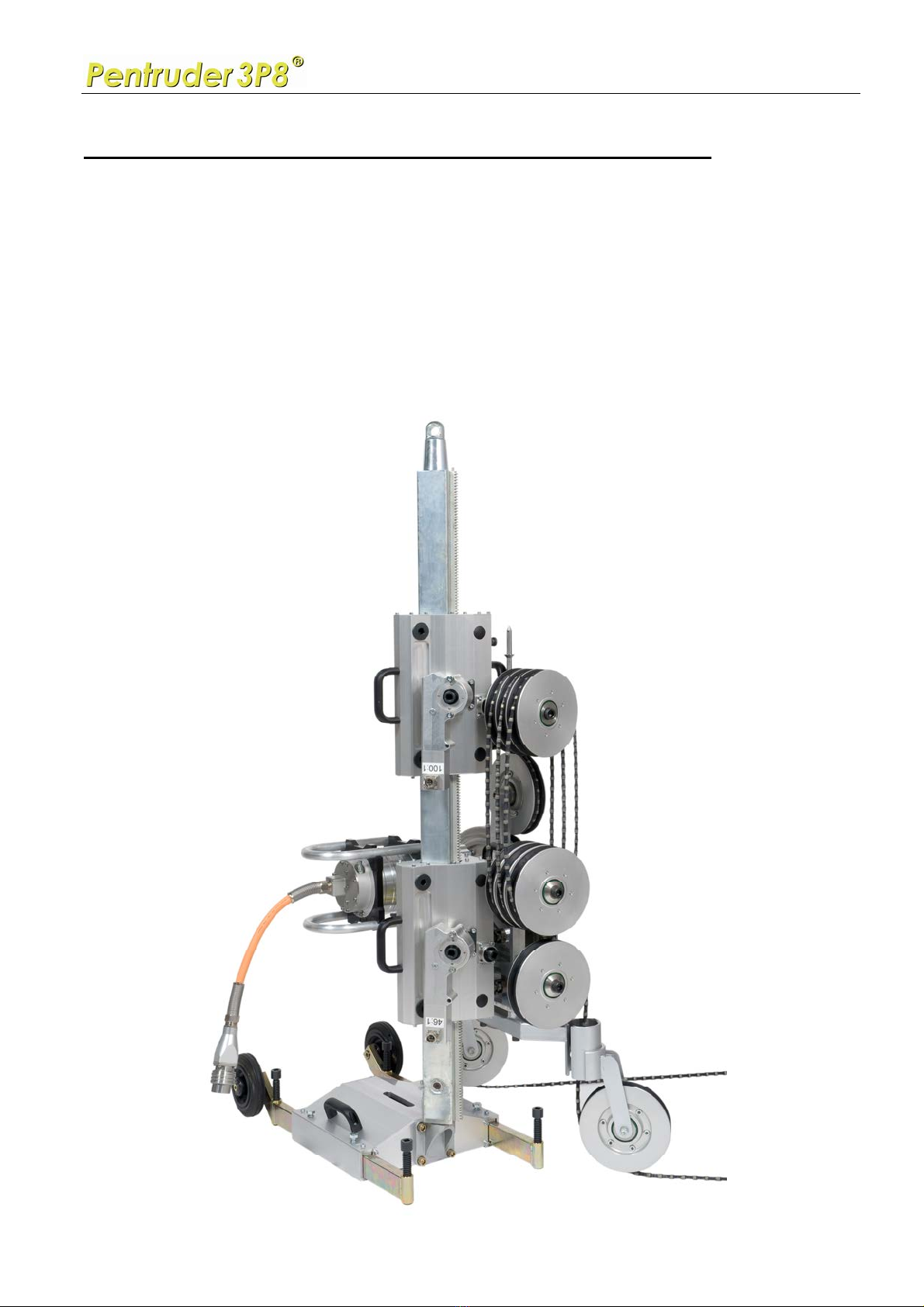
Why does the 3P8 use so many rollers in the wire magazine?
There are four loops of wire being tensioned, three in the magazine, and one on the return or
slack side, this means that if the upper carriage moves 1.0 m, 3,3 ft you have stored eight
meters in the magazine. Objects 2.2 x 10 m, 7,2 x 33 ft., has been cut without shortening the
wire, and then the carriage was moved over 2.5 meters, 8.2 ft up, taking in over 20 meters, 65
ft. of wire!
All 3 + 3 rollers in the magazine are used, always. The feed regulation parameters are based
on the resistance and force needed to tension the wire when it runs over all rollers.

Operators Manual - High Frequency driven Pentruder 3P8 Wire Saw
Pentruder - Stronger than ever! Applying Standards That Are Years Ahead Of the Competition.
Tractive AB 28 January 2009 Page 7
General safety instructions
This wire saw may not be used before the operator is fully educated by our sales agent in
handling the machine. Adequately trained personnel are required for planning and cutting. It is
the obligation of the buyer / owner of the equipment to make sure that the operator really has
received the information necessary to operate and take care of the machine in a correct and
safe way. Incorrect handling can lead to serious or even fatal injury to the operator and
persons in proximity to the machine.
Tractive AB is not responsible for damage on property or persons whether they originate from
incorrect handling or deficient maintenance or as a consequence from not checking the
machine for damage and/or defects before taking it into use.
The following safety instructions are important to know and follow:
•General safety precautions means that all persons working with, or in the proximity to
the wire sawing machine should wear safety equipment, i.e. protection helmet,
protection shoes, gloves, eye and ear protectors. Other safety regulations at the work
place must be followed. The noise level when sawing might lead to permanent hearing
disorders if not ear guards are worn.
•Always check that the equipment is in faultless condition and that all functions are in
order before work is commenced.
•Warning! The power pack must be disconnected from the power supply by removing
the 32 (red) or 63 Amp (blue) plug and cable from the power pack before any other
electric connections on the power pack are made.
•The power pack must always be switched off and the 32 (red) or 63 Amp (blue) plug
and cable disconnected from the power pack before any kind of service is commenced.
•Mounting and dismounting of the wire saw may only take place when the power to the
main pulley drive motor is disconnected from the power pack by removing the electric
connector on the HF-motor or on the power pack.
•To maintain the level of safety inherent in the design of this machine, only Tractive
original spare parts may be fitted. Tractive AB disclaims all responsibility for damage
occurring as a result of use of non original parts.
•The power pack must only be operated when it is standing on its rubber feet.
•The power pack is water cooled and must be drained from water when the ambient
temperature is in the proximity of or below 0 degrees Celsius, or 32°F.
•The electric power transistor units are water cooled and the water pressure must be
limited to max 5 bar or 70 PSI. The incoming water supply may only be connected to
the lower right hand connector on the power pack. The quick disconnect couplings may
not be replaced with couplings that are not fully open when disconnected.

Operators Manual - High Frequency driven Pentruder 3P8 Wire Saw
Pentruder - Stronger than ever! Applying Standards That Are Years Ahead Of the Competition.
Tractive AB 28 January 2009 Page 8
General safety instructions, continued
•The operator should have good supervision over the wire saw and inform passing persons
about possible risks. Unauthorized persons shall not be within the risk area (the area
around the wire saw).
•Always lift modules of the wire saw ergonomically correct. The Pentpak is not provided
with handles for lifting.
•The base plate must always be securely anchored to perform sawing.
•Never run the wire saw without water cooling to the water pack and HF-motor. Should
the cooling water seeze to function, stop the machine immediately.
•Before sawing is commenced all persons involved must know how the emergency stop
buttons are working.
•Only connect the Pentpak 418, 422 or 427 power packs to Pentruder HF-motors or
other HF-equipment which has been manufactured or approved by Tractive AB .
Safety precautions on site
Check with the foreman responsible that all necessary precautions have been performed
before commencing work. Await the approval of the safety precautions and mounting position
of the machine from the responsible person before work is commenced.
Emergency stop
Show all persons involved in the job how the emergency stop on the machine is working.
Warning! If there is a possibility that pieces of material cut away when wire sawing may fall
causing injury or damage to persons or property then they must be secured before starting
work. The risk area must be roped off and a responsible person left in charge, in a safe place,
to prevent entry of unauthorised persons.

Operators Manual - High Frequency driven Pentruder 3P8 Wire Saw
Pentruder - Stronger than ever! Applying Standards That Are Years Ahead Of the Competition.
Tractive AB 28 January 2009 Page 9
Operators Manual - High Frequency driven Pentruder 3P8 Wire Saw
Pentruder - Stronger than ever! Applying Standards That Are Years Ahead Of the Competition.
Tractive AB 28 January 2009 Page 10
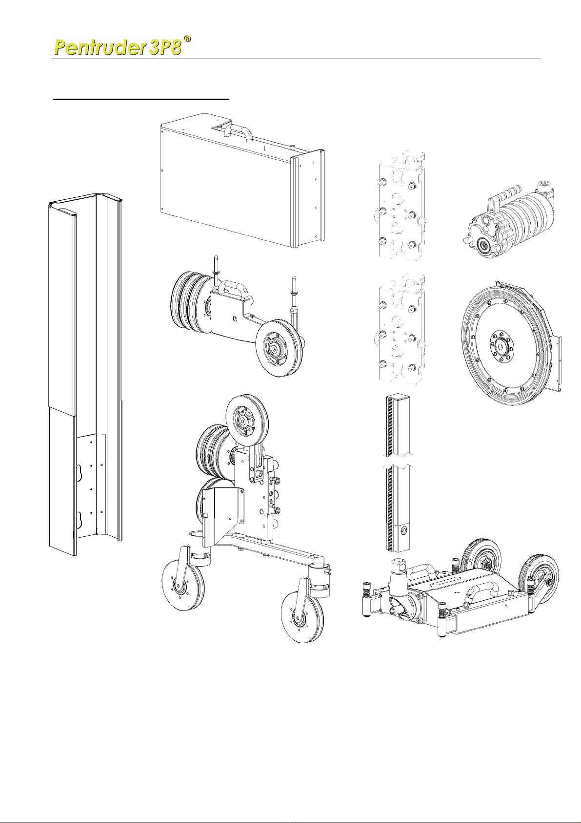
Machine modules overview
1. Base plate BE1 with fixed cone coupling or BE2 with swiveling cone coupling
2. Column 0.5-1.2-1.5-2.0m 3. Lower carriage with feed unit
4. Upper carriage 5. Friction brake
6. Electric feed unit 7. Lower assembly
8. Main drive pulley 9. Upper assembly
10. Guard, main drive pulley 11. Guard, upper assembly,
12. Telescopic guard, magazine rollers 13. Telescopic guard, slack side
11
9
7
2
3
4
1
1
6
5
12
13
7
Operators Manual - High Frequency driven Pentruder 3P8 Wire Saw
Pentruder - Stronger than ever! Applying Standards That Are Years Ahead Of the Competition.
Tractive AB 28 January 2009 Page 11
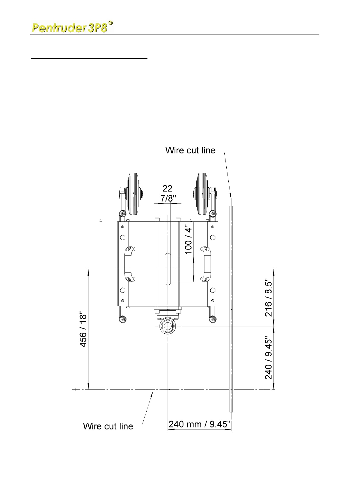
How to position the base plate
1. Be observant on what material the base plate will be mounted on. For safety
reasons it is very important that the base plate is properly fastened. If mounted on
brick or porous concrete we recommend to fasten the base plate with M16 / 5/8”
through bolts.
2. The wire cut line will be as shown in the drawing below. Please note: The column
can rotate around its own axis, and be locked in any position. Therefore you may
prefer to measure your anchor position from the center of the column.

Operators Manual - High Frequency driven Pentruder 3P8 Wire Saw
Pentruder - Stronger than ever! Applying Standards That Are Years Ahead Of the Competition.
Tractive AB 28 January 2009 Page 12
Overview cut lines – view from top
Operators Manual - High Frequency driven Pentruder 3P8 Wire Saw
Pentruder - Stronger than ever! Applying Standards That Are Years Ahead Of the Competition.
Tractive AB 28 January 2009 Page 13
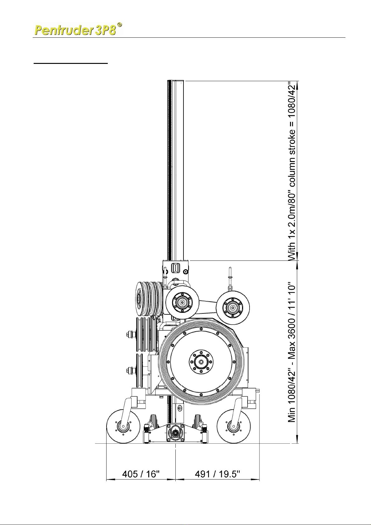
Stroke of carriage

Operators Manual - High Frequency driven Pentruder 3P8 Wire Saw
Pentruder - Stronger than ever! Applying Standards That Are Years Ahead Of the Competition.
Tractive AB 28 January 2009 Page 14
Standard mounting sequence
1. Base plate
2. Column or columns
3. Lower carriage
4. Upper carriage
5. Lower assembly
6. Main drive pulley
7. HF-motor
8. Upper assembly
9. Electric cables to HF-motor and feed unit
10.Cooling water hoses to power pack and HF-motor
11.Guards
Fig. . Base plate-BE2 with swivelling quick coupling.
On BE2 the conical quick coupling can be swivelled sideways in increments of 5°.
We strongly recommend the BA1 base plate for wire sawing. It has a fixed coupling, and is
more rigid than the BA2 type of swivelling coupling,
Columns
Three types of columns are available:
a) Columns with a female / male configuration, meaning that each column is fitted with a
female conical quick release coupling at one end, and a male coupling at the other end. It can
be extended in each end.
b) Columns with a female coupling in one end, and a Jack Screw in the other end. It can be
extended only in the end with the female coupling.
c) Columns with a female coupling in one end, and a blanking plug in the other end. It can be
extended only in the end with the female coupling.
The columns are available in four lenghts, 0.5 m, 1.2 m, 1.5 m and 2.0 m, 20”, 47.2” 59” and
79”.
The columns, with the conical quick release coupling unlocked, can rotate around its own
axis, and great flexibility is offered to simplify set-up.
Operators Manual - High Frequency driven Pentruder 3P8 Wire Saw
Pentruder - Stronger than ever! Applying Standards That Are Years Ahead Of the Competition.
Tractive AB 28 January 2009 Page 15
1. Mount the base plate
Bolt the base plate to a solid object using
an M16 / 5/8” anchor bolt. Use only high
quality anchors and bolts. Adjust the
support legs (see fig. 2). Level the base
plate using the four leveling screws.
2. Mount the columns or columns
The column is locked by turning the
eccentric bolt Clockwise.
To release the column, the eccentric is
turned Counter Clockwise until it lifts
from the cone. To remove the eccentric
bolt, turn it slightly Clockwise again until
the load on the bolt is gone, and then pull
out the bolt, and then the column can be
removed. Do not insert your fingers in the
bolt hole!! Fig. 2. Base plate BE2 and column-CN 0.5 F/M-70.
Fig. 2. Base plate BE2 and column-CN 0.5 F/M-70.
Fig. 2. Base plate BE2 and column-CN 0.5 F/M-70.
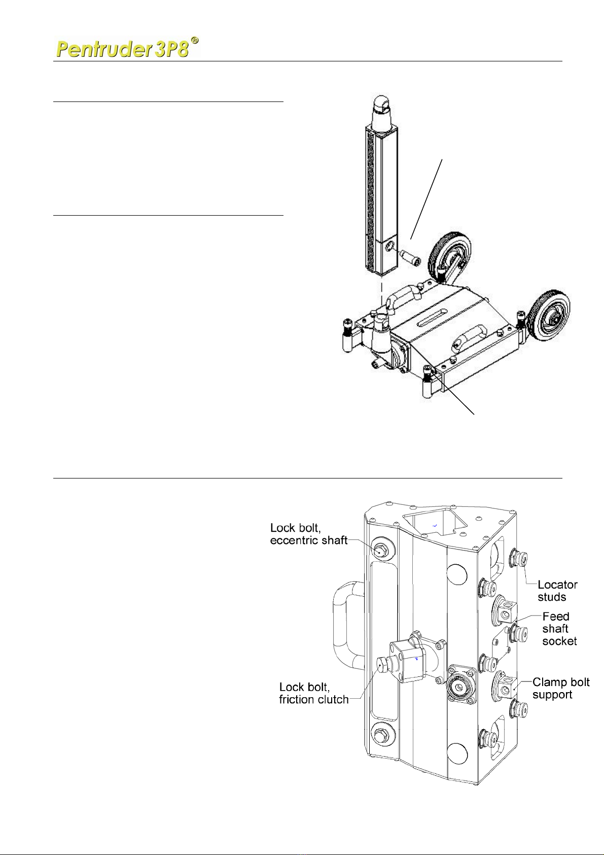
3. Mount the lower carriage on the column
1. Loosen the socket on the
friction clutch one turn.
(19 mm / 3/4” spanner)
2. Slide the carriage over the
column
3. Adjust the height of the
carriage by turning the feed
shaft socket with a ratchet or
knuckle bar.
4. Tighten the friction clutch
socket.
Tighten firmly, but do not over
tighten!
Eccentric cam bolt
4x levelling screws

Operators Manual - High Frequency driven Pentruder 3P8 Wire Saw
Pentruder - Stronger than ever! Applying Standards That Are Years Ahead Of the Competition.
Tractive AB 28 January 2009 Page 16
4. Mount the upper carriage on the column
1. Loosen the socket on the friction clutch one turn. (19 mm / 3/4” spanner)
2. Slide the carriage over the column
3. Adjust the height of the carriage by turning the feed shaft socket with a ratchet or
knuckle bar.
4. Tighten the friction clutch socket.
Tighten firmly, but do not over tighten!
Fig. 4. Carriage CE1 with Electric feed unit ET100.
Operators Manual - High Frequency driven Pentruder 3P8 Wire Saw
Pentruder - Stronger than ever! Applying Standards That Are Years Ahead Of the Competition.
Tractive AB 28 January 2009 Page 17
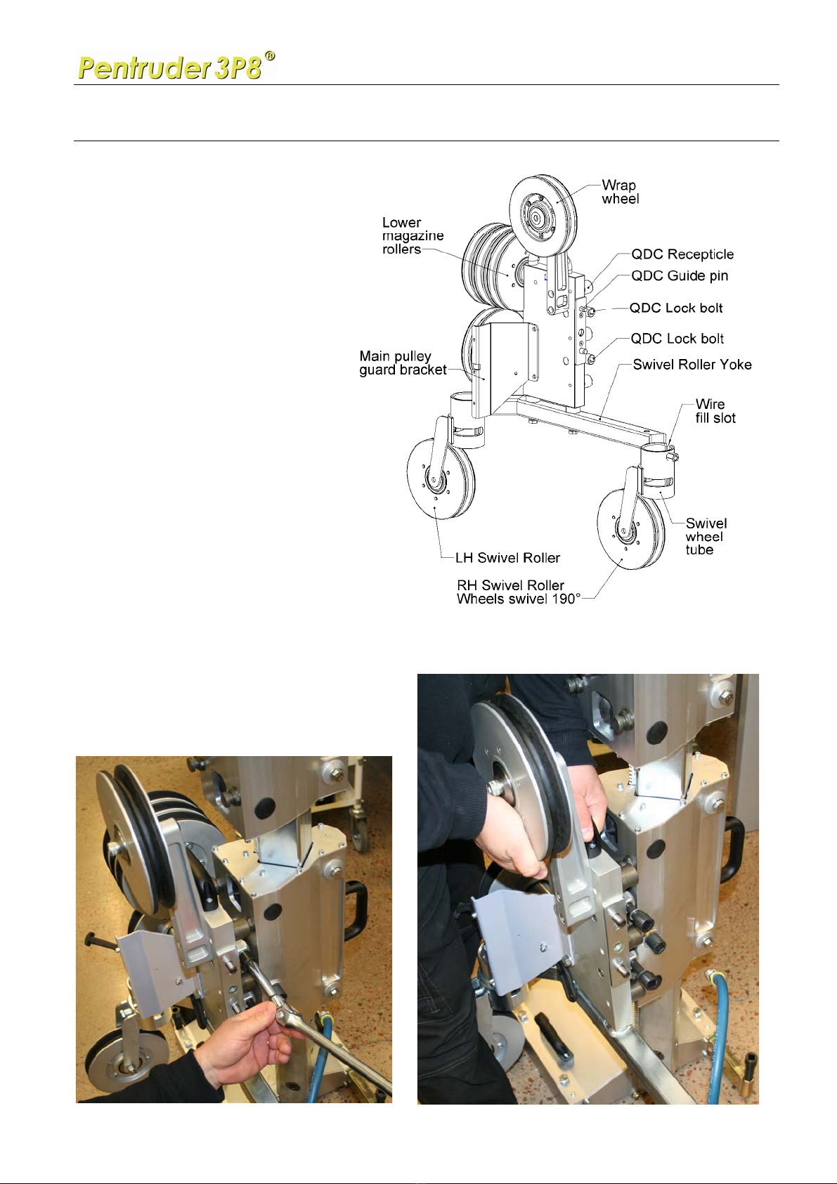
5. Attach the lower magazine and swivel roller assembly
Normally the lower assembly unit is
mounted on the carriage with the
swiveling rollers pointing towards
the surface the base plate is
mounted on.
Warning: Be careful after having
mounted the carriages on the
column.
Make sure the friction couplings
are tightened to avoid injuries, this
applies to both carriages. Do not
over tighten the clamp socket!
Slide the complete lower assy
sideways with the Quick Diconnect
Coupling recepticles engaging with the
locator studs on the carriage.
Tighten the QDC lock bolts firmly, but do
NOT over tighten!

Operators Manual - High Frequency driven Pentruder 3P8 Wire Saw
Pentruder - Stronger than ever! Applying Standards That Are Years Ahead Of the Competition.
Tractive AB 28 January 2009 Page 18
6. Attach the main drive pulley assembly
Attach the main drive pulley assembly on the lower magazine assembly by mating the two
dowel pins to the dowel holes in the magazine plate.
Tighten the lock bolt with a 14 mm Allen key socket and a long ½” extension.
Operators Manual - High Frequency driven Pentruder 3P8 Wire Saw
Pentruder - Stronger than ever! Applying Standards That Are Years Ahead Of the Competition.
Tractive AB 28 January 2009 Page 19
7. Attach the main drive HF-motor to the pulley assembly
Attach the HF-motor to the pulley assembly by entering the locator dowels in to the holes in
the pulley assembly plate. Tighten the lock screws with an 8 mm allen key / 5/16”. Rock the
main drive pulley slightly back and forth to make the spline shaft mesh with the hF-motor.
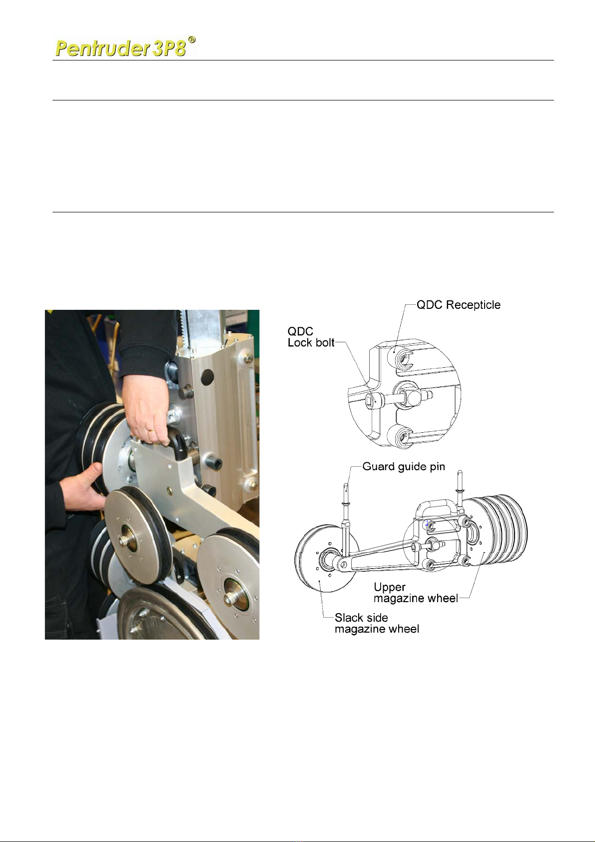
8. Attach the upper magazine assembly
Attach the upper magazine assembly by sliding the assembly sideways onto the locator studs
on the upper carriage. Use the lower four studs. Tighten the QDC lock bolts firmly, but do
NOT over tighten!
Operators Manual - High Frequency driven Pentruder 3P8 Wire Saw
Pentruder - Stronger than ever! Applying Standards That Are Years Ahead Of the Competition.
Tractive AB 28 January 2009 Page 20
9. Attach HF-motor cord and the 24V feed motor cord
Attach the main drive HF-motor cord, and the 24V feed motor cord.
10. Attach water hoses
Attach the water hoses to the power pack, the HF-motor and connect the hose from the motor
bracket plate to the swivel wheel yoke.
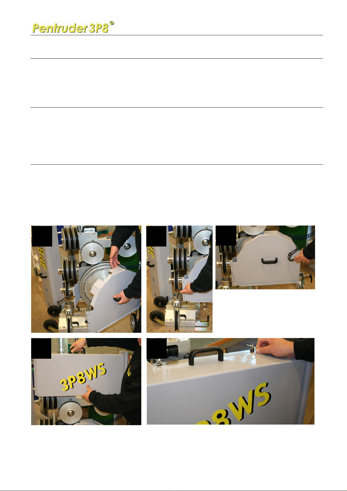
11. Attach guards
After the wire has been started, very slowly, and has cut a shallow groove, the guards can be
fitted. The start up procedure is described on page 27.
1
2
3
4
5
Table of contents
Other Tractive Saw manuals


