Trademark WEED EATER GTI 15T User manual

IMPORTANT
MANUAL
Do
Not
Throw
Away
TRADEMARK*
A
WARNING:
Read
the
Operator’s
Manual
and
Follow
All
Warnings
and
Safety
Instructions.
Failure
To
Do
So
Can
Result
in
Serious
Injury.
OPERATOR’S
MANUAL
MODEL;
Gxr
15
T
GAS
POWERED
TRIMMER
4;
^CUSTOMER
4
ASSISTANCE
i-800-554-6723
I
SEE
BACK
COVER
FOR
DETAILS!
^
Always
Wear
Eye
Protection
TABLE
OF
CONTENTS
WARNINGS
AND
SAFETY
INSTRUCTIONS
...
3
KNOWYOURUNIT.
5
ASSEMBLY.
6
ACCESSORIES
.
8
FUELING
YOUR
ENGINE.
9
STARTING
YOUR
ENGINE.10
USING
YOUR
TRIMMER.
GENERAL
MAINTENANCE
.15
CUSTOMER
ASSISTANCE
SERVICE...
Back
Cover
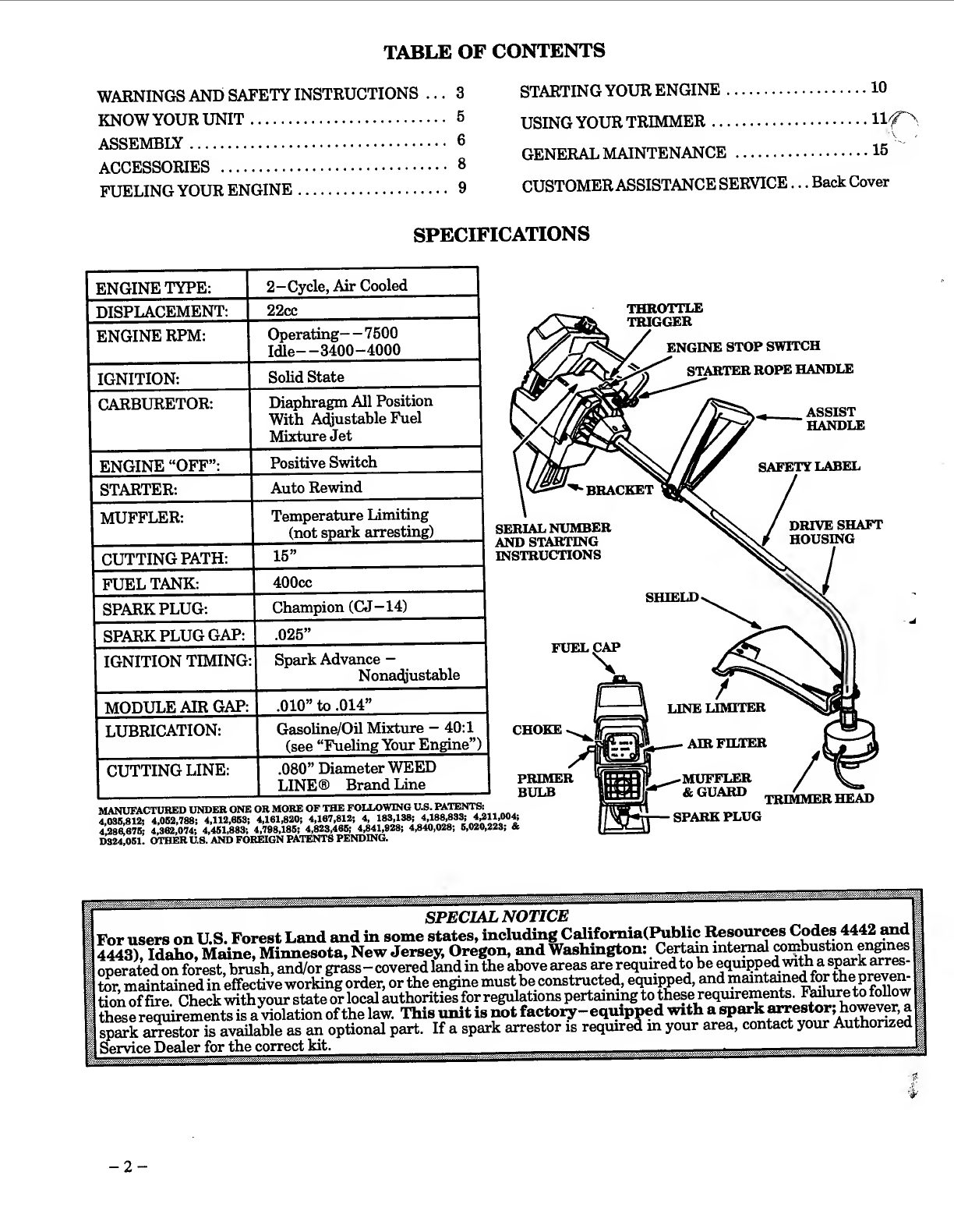
SPECIFICATIONS
ENGINE
TYPE:
DISPLACEMENT:
ENGINE
RPM:
IGNITION:
_
CARBURETOR:
ENGINE
“OFF”:
STARTER:
_
MUFFLER:
CUTTING
PATH:
FUEL
TANK:
SPARKPLUG:
SPARK
PLUG
GAP:
IGNITION
TIMING:
MODULE
AIR
GAP:
LUBRICATION:
|
CUTTING
LINE:
2—Cycle,
Air
Cooled
_
22cc
__
Operating—
7500
Idle—3400-4000
_
Solid
State
_
Diaphragm
All
Position
With
Adjustable
Fuel
M
ixture
Jet
_
Positive
Switch
_
Auto
Rewind
_
Temperature
Limiting
(not
spark
arresting)
_
15”
_
400cc
_
Champion
(CJ-14)
_
.025”
_
Spark
Advance
—
Nonadjustable
.010”
to
.014”
_
Gasoline/Oil
Mixture
-
40:1
(see
“Fueling
Your
Engine”)
.080”
Diameter
WEED
LINE®
Brand
Line_
THROTTLE
TRIGGER
ENGINE
STOP
SWITCH
y
STARTER
ROPE
HANDLE
ASSIST
HANDLE
■
B
RACKET
SERIAL
NUMBER
AND
STARTING
INSTRUCTIONS
SAFETY
LABEL
DRIVE
SHAFT
HOUSING
SHIELD.
FUEL
CAP
CHOKE
PRIMER
BULB
MANUFACTURED
UNDER
ONE
OR
MORE
OF
THE
FOLLOWING
U.S.
PATENTS:
4,03S,912;
4,062,789;
4,112,863;
4,161,820;
4,187,812;
4,
183,138;
4
286.676;
4,362,074;
4,461,983;
4,798,186;
4,823,466;
4,841,929;
4,940,028;
6,020,223;
&
D324,061.
OTHER
U.8.
AND
FOREIGN
PATENTS
PENDING.
/
^
LINE
LIMITER
AIR
FILTER
^
MUu'P'LiEjR
&
GUARD
,
SPARK
PLUG
TRIMMER
HEAD
A
WARNINGS
AND
SAFETY
INSTRUCTIONS
(See
Additional
Safety
Instructions
throughout
this
Manual)
^^ARNING
■
“
THIS
POWER
TOOL
CAN
BE
DANGEROUS!
This
unit
can
cause
serious
injury
or
hhndness
to
the
operator
and
others.
The
warnings
and
safety
instiructions
in
this
manual
must
be
fol¬
lowed
to
provide
reasonable
safety
and
efficiency
in
using
this
unit.
The
operator
is
responsible
for
following
the
warnings
and
instructions
in
this
manual
and
on
the
unit.
Read
the
entire
Operator’s
Manual
before
assem¬
bling
and
using
this
unit!
Restrict
the
use
of
this
power
tool
to
persons
who
read,
understand
and
follow
the
warnings
and
instructions
in
this
manual
and
on
the
unit.
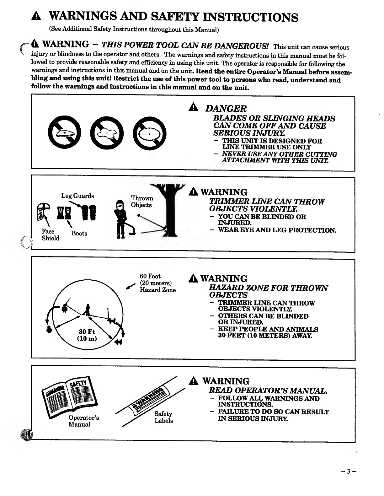
A
DANGER
BLADES
OR
SUNGING
HEADS
CAN
COME
OFF
AND
CAUSE
SERIOUS
INJURY.
-
Tins
UNTTIS
DESIGNED
FOR
LINE
TRIMMER
USE
ONLY
-
NEVER
USE
ANY
OTHER
CUTTING
ATTACHMENT
WITH
THIS
UNIT.
Face
Shield
Leg
Guards
siW
Thrown
Objects
Boots
A
WARNB^G
TRIMMER
LINE
CAN
THROW
OBJECTS
VIOLENTLY.
-
YOU
CAN
BE
BLINDED
OR
INJURED.
-
WEAR
EYE
AND
LEG
PROTECTION.

WARNINGS
AND
SAFETY
INSTRUCTIONS....(Contmued)
A
OPERATOR
SAFETY
•
Always
wear
safety
eye
protection.
•
^ways
wear
long
pants,
boots
and
gloves.
Wear¬
ing
s^ety
leg
guards
is
recommended.
Do
not
go
barefoot
or
wear
sandals,
jewelry,
short
pants,
loose
clothing,
or
clothing
with
loosely
hanging
ties,
straps,
tassels,
etc.;
they
can
be
caught
in
moving
parts.
•
Secure
hair
so
it
is
above
shoulder
length.
•
Do
not
operate
this
unit
when
you
are
tired,
ill,
or
under
the
influence
of
alcohol,
drugs,
or
medica¬
tion.
•
Wear
hearing
protection
if
you
use
this
unit
for
more
than
1—1/2
hours
per
day.
•
Never
start
or
run
the
engine
inside
a
closed
room
or
building.
Breathing
exhaust
fumes
can
kill.
•
Keep
handles
free
of
oil
and
fuel.
A
UNITIMAINTENANCE
SAFETY
•
Look
for
and
replace
damaged
or
loose
parts
be¬
fore
each
use.
Look
for
and
repair
fuel
leaks
before
use.
Keep
the
unit
in
good
working
condition.
•
Replace
trimmer
head
parts
that
are
chipped,
cracked,
broken,
or
damage
in
any
other
way
be¬
fore
using
the
unit.
•
Use
only
.080”
diameter
WEED
EATER®
brand
line.
Never
use
wire,
rope,
string,
etc.
•
Make
sure
the
unit
is
assembled
correctly
as
listed
in
this
manual.
•
Make
carburetor
adjustments
with
the
lower
end
supported
to
prevent
the
trimmer
line
from
con¬
tacting
any
object.
•
Keep
others
away
when
making
carburetor
ad¬
justments.
•
Disconnect
the
spark
plug
before
performing
maintenance
except
carburetor
adjustments.
•
Use
only
genuine
WEED
EATER
accessories
and
replacement
parts
as
recommended
for
this
unit.
A
FUEL
SAFETY
•
Mix
and
pour
fuel
outdoors.
•
Keep
away
from
sparks
or
flames.
•
Use
a
container
approved
for
fuel.
•
Do
not
smoke
or
allow
smoking
near
fuel
or
the
unit
or
while
using
the
unit.
•
Wipe
up
all
fuel
spills
before
starting
engine.
•
Move
at
least
10
feet
(3
meters)
away
from
fueling
site
before
starting
engine.
▲
•
Stop
engine
before
removing
fuel
cap.
v
•
Empty
the
fuel
tank
before
storing
the
unit.
Use
up
fuel
left
in
the
carburetor
by
starting
the
en¬
gine
and
letting
the
engine
run
until
it
stops.
•
Store
unit
and
fuel
in
an
area
where
fuel
vapors
cannot
reach
sparks
or
open
flames
from
water
heaters,
electric
motors
or
switches,
furnaces,
etc.
A
CUTTING
SAFETY
•
Inspect
the
area
to
be
cut
before
each
use.
Remove
objects
(rocks,
broken
glass,
nails,
wire,
string,
etc.)
which
can
be
thrown
or
become
entangled
in
the
trimmer
head.
•
Keep
others
including
children,
animals,
bystand¬
ers
and
helpers
outside
the
60
foot
(20
meter)
Haz¬
ard
Zone.
Stop
the
engine
immediately
if
you
are
approached.
•
Always
keep
the
engine
on
the
right-hand
side
of
your
body.
•
Hold
the
unit
firmly
with
both
hands.
•
Keep
firm
footing
and
balance.
Do
not
over¬
reach.
•
Keep
the
trimmer
head
below
waist
level.
•
Do
not
raise
the
engine
above
your
waist.
•
Keep
all
parts
of
your
body
away
from
trimmer
head
and
muffler
when
engine
is
running.
•
Cut
from
your
left
to
your
right.
•
Use
only
forjobs
explained
in
this
manual
A
TRANSPORTING
AND
STORAGE
•
Stop
the
unit
before
carrying.
•
Keep
the
muffler
away
from
yoim
body.
•
Mow
the
engine
to
cool,
and
secure
the
unit
be¬
fore
storing
or
transporting
in
a
vehicle.
•
Empty
the
fuel
tank
before
storing
or
transport-
ing
the
unit.
Use
up
fuel
left
in
the
carburetor
by
starting
the
engine
and
letting
the
engine
run
un¬
til
it
stops.
•
Store
unit
and
fuel
in
an
area
where
fiiel
vapors
cannot
reach
sparks
or
open
flames
from
water
heaters,
electric
motors
or
switches,
furnaces,
etc.
•
Store
unit
so
line
limiter
cannot
accidentally
cause
injury.
The
unit
can
be
hung
by
the
bracket
below
the
engine
or
by
drive
shaft
housing.
•
Store
the
unit
out
of
the
reach
of
children.
Ifsituatio^
occur
which
are
not
covered
in
this
manual,
use
care
and
good
judgment.
If
you
need
assistance,
contact
your
Authorized
Service
Dealer
or
the
CUSTOMER
ASSISTANCE
HOTLINE,
1
-800
-554-6723.
SAFETY
NOTICE
must
Ytmnitrki*
r*irkQoi«r
_
j
ja*
_
powcr
tools
On
8.
Gontmu&l
snd.
rGgulai*
basis

A.
INTRODUCTION
Your
Trimmer
is
a
versatile
product
developed
for
large
lawns
and
to
make
short
work
of
a
variety
of
lawn
care
tasks
—
trimming,
scalping,
mowing,
and
sweeping.
Special
Features
Include:
•
ComforTouch®
Anti-vibration
Handle
•
All—Position
Carburetor
•
Adjustable
Assist
Handle
•
TAP-N-GO®
Cutting
Head
•
15”
Cutting
Path
B.
UNPACKING
INSTRUCTIONS
1.
After
removing
the
contents
from
the
carton,
check
parts
against
the
Carton
Contents
list.
2.
Examine
the
parts
for
damage.
Do
not
use
damaged
parts.
3.
Notify
your
WEED
EATER
dealer
immediately
if
apart
is
missing
or
damaged.
NOTE:
Your
unit
has
been
shipped
with
a
plastic
shipping
i^ard
over
the
primer
bulb
(see
Specifications”
for
location).
Remove
and
discard
the
plastic
shipping
guard.
NO'l'K;
It
is
normal
to
hear
the
fuel
filter
rattle
in
£m
empty
fuel
tank.
C.
C
ARTON
CONTENTS
1.
Engine
1
2
.
Drive
Shaft
Assembly
w/Safety
Label
1
3.
Trimmer
Head
Shield
1
4.
Line
Trimmer
Head
1
5.
Assist
Handle
1
-
-
Operator’s
Manual
1
—
Loose
Parts
Bag
1
LOOSE
PARTS
BAG
CONTENTS:
6.
Hex
Wrench
(not
shown)
1
7.
3.2
oz.
40:1
Engine
Oil
(not
shown)
1
A.
Screw
2
B.
Screw
2
C.
Screw
1
D.
Dust
Cup
1
E.
Bracket
1
F.
Wing
Nut
1
G.
Flat
Washer
1
H.
Lock
Nut
2
iTflARDWARE
CHART
SHOWN
ACTUAL
SIZE
Refer
to
the
hardware
reference
letters
below
during
assembly.
^TE:
This
Hardware
is
packaged
in
the
Plastic
Bag.
ASSEMBLY
(If
tool
is
received
assembled,
repeat
all
steps
in
this
section
to
be
sure
assembly
is
correct
and
is
ad¬
justed
for
the
operator.)
PREPARATION
This
Manual
is
designed
to
help
you
assemble
the
tool
and
to
provide
its
s^e
operation.
It
is
important
that
you
read
the
entire
manual
to
become
famihar
with
the
tool
before
you
bemn
assembly.
If
you
have
any
questions
or
need
further
assistance,
call
our
CUSTOMER
ASSISTANCE
HOTLINE
at
1-800-554-6723.
1.
Read
your
Operator’s
Manual
2.
Tools
you
will
need:
-
Hex
Wrench
provided
with
the
tool.
-
Adjustable
Wrench
-
Standard
Screwdriver
ASSEMBLY
STEPS
(Refer
to
illustrations)
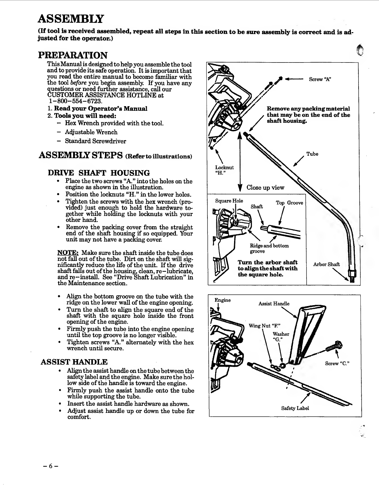
DRIVE
SHAFT
HOUSING
•
Place
the
two
screws
“A.
”
into
the
holes
on
the
engine
as
shown
in
the
illustration.
•
Position
the
locknuts
“H.”
in
the
lower
holes.
•
Tighten
the
screws
with
the
hex
wrench
(pro¬
vided)
just
enough
to
hold
the
hardware
to¬
gether
while
holding
the
locknuts
with
your
other
hand.
•
Remove
the
packing
cover
from
the
straight
end
of
the
shaft
housing
if
so
equipped.
Your
unit
may
not
have
a
pacMng
cover.
NOTE:
Make
srnre
the
shaft
inside
the
tube
does
not
fall
out
of
the
tube.
Dirt
on
the
shaft
will
sig¬
nificantly
reduce
the
life
of
the
unit.
If
the
drive
shaft
falls
out
of
the
housing,
clean,
re-lubricate,
and
re-install.
See
“Drive
Shaft
Lubrication”
in
the
Maintenance
section.
%J
•
Align
the
bottom
groove
on
the
tube
with
the
ridge
on
the
lower
wall
of
the
engine
opening.
•
Turn
the
shaft
to
align
the
square
end
of
the
shaft
with
the
square
hole
inside
the
front
opening
of
the
engine.
•
Firmly
push
the
tube
into
the
engine
opening
until
the
top
groove
is
no
longer
visible.
•
Tighten
screws
“A.”
alternately
with
the
hex
wrench
until
secure.
ASSIST
HANDLE
•
Align
the
assist
handle
on
the
tube
between
the
safety
label
and
the
en^ne.
Make
sure
the
hol¬
low
side
of
the
handle
is
toward
the
engine.
•
Firmly
push
the
assist
handle
onto
the
tube
while
supporting
the
tube.
•
Insert
the
assist
handle
hardware
as
shown.
•
Adjust
assist
handle
up
or
down
the
tube
for
comfort.
-
6
-

TRIMMER
HEAD
•
Place
the
dust
cup
“D.
”
over
the
hex
nut
on
the
bottom
of
the
tube
-
see
illustration.
The
hex
nut
should
fit
completely
inside
the
dust
cup.
•
Hold
the
dust
cup
with
a
wrench
to
keep
the
ar¬
bor
shaft
from
turning.
•
Thread
the
trimmer
head
onto
the
arbor
shaft
against
the
dust
cup
and
hand
tighten
firmly.
NOTE:
Unless
trimmer
head
is
tightened
ade¬
quately,
it
can
unthread
when
engine
is
started
or
stopped.
If
this
situation
occurs,
reinstall
the
trimmer
head
and
tighten
more
securely.
SHIELD
AT
TACHMENT
^
.
AWARNING
The
shield
must
be
properly
installed.
The?
shield
provides
partial
protection
from
the
risk
of
thrown
objects
to
the
operator
and
others
ntir^
is
equipped
with
a
line
limiter
which
cuts
excess
line
to
th
e
proper
length.
AWARNING
^
Do
not
alter
or
remove
the
bracket
tab.
When
in¬
stalled
correctly,
the
bracket
tab
ensures
proper
shield
alignment.
Failure
to
install
the
shield
in
position
shown
in
illustration
can
result
in
seri-
ous
injury
to
the
operator.
CAUTION;
I
The
line
limiter
(on
the
underside
of
the
shield)
is
sharp
and
can
cut
you.
!
•
Match
the
tab
on
bracket
“E.”
with
the
hole
in
?
the
tube.
•
Attach
the
shield
to
the
bracket
with
the
two
screws
“B.”
Tighten
evenly
and
securely.
NOTE
;
Although
a
screwdriver
slot
is
pro¬
vided
in
screws
it
is
easier
to
install
the
screws
with
a
wrench
or
socket.
OPERATING
POSITION
•
Before
starting
the
engine,
stand
as
shown
and
check
for
the
following:
•
Left
arm
fully
extended,
hand
holding
assist
handle.
•
Right
arm
shghtly
bent,
hand
holding
top
handle,
fingers
on
throttle
trigger.
•
Top
handle
below
waist
level.
•
Weight
of
tool
evenly
distributed
between
arms.
•
Without
operator
bending
over,
the
trimmer
head
is
near
and
parallel
to
the
ground
and
easily
contacts
the
material
to
be
cut.
•
A^ust
the
assist
handle
up
or
down
the
drive
shaft
housing
(but
above
the
safety
labels)
to
a
comfortable
position.
•
Rotate
assist
handle
from
left
to
right
to
tilt
the
angle
of
the
trimmer
head
when
cutting
a
large,
sloped
area
such
as
a
ditch
bank.
NOTE
;
It
is
possible
that
a
small
space
will
be
left
between
the
bracket
and
the
shield
when
the
screws
are
fully
tightened.
-
7
-

ACCESSORIES
ITEM
SAFETY
FACE
SfflELD.
SAFETY
GLASSES
.
SAFETY
LEG
GUARDS.
WEED
EATER®
40:1
2-CYCLE
ENGINE
OIL
—3.2
oz.
container
(mix
with
1
gallon
gasoline)
...
—8
oz.
container
(mix
with
2-1/2
gallons
gasoline)
—19.6
oz.
container.
FUEL
CAP
tap-n-g6®
iii
TRIMMER
HE^
!.!!!!!!!!!!!!!!
SPOOL
W/LINE.
NYLON
CUTTING
LINE
—80
Ft.
(.080
Dia.)
Cutting
Line
.
—200
Ft.
(.080
Dia.)
Cutting
Line
.
—400
Ft.
(.080
Dia.)
Cutting
Line
.
FLEX
SHAFT
LUBE.
AIR
FILTER
.
SPARKPLUG.
STOCK
NO.
.
952-701601
.
952-701645
.
952-701600
.
952-030133
.
952-030128
.
952-031138
,.
952-701583
..
952-701618
,.
952-701619
.
952-701534
.
952-701595
.
952-701590
.
952-701570
.
952-701614
..
530-030077
NOTES
-
8
-
FUELING
YOUR
ENGINE
\
FUEL
SAFETY
•
Be
sure
to
read
the
fuel
safety
section
on
page
4
of
this
manual
before
you
begin.
•
If
you
do
not
understand
the
fuel
safety
section
DO
NOT
attempt
to
fuel
your
unit;
seek
help
&om
someone
that
does
under¬
stand
the
fuel
safety
section
or
call
our
Customer
Assistance
Hotline
at
1-800-554-6723.
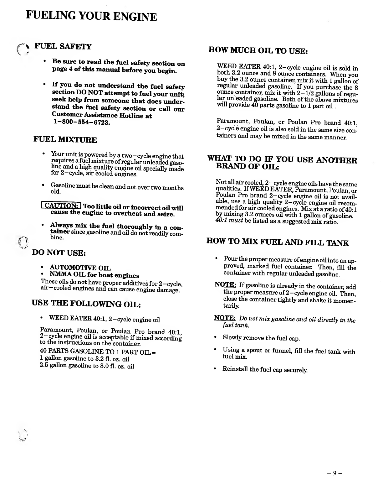
FUEL
MIXTURE
HOW
MUCH
OIL
TO
USE:
)^ED
EIATER
40:1,
2-cycle
engine
oil
is
sold
in
both
3.2
ounce
and
8
ounce
containers.
When
you
buy
the
3.2
ounce
container,
mix
it
with
1
gallon
of
regular
unleaded
gasoline.
If
you
purchase
the
8
ounce
container,
mix
it
with
2-1/2
gallons
of
regu-
lar
unleaded
gasohne.
Both
of
the
above
mixtures
will
provide
40
parts
gasoline
to
1
part
oil.
Paramount,
Poulan,
or
Poulan
Pro
brand
40:1,
2-cycle
engine
oil
is
also
sold
in
the
same
size
con¬
tainers
and
may
be
mixed
in
the
same
manner.
•
Your
umt
is
powered
by
a
two—qrcle
engine
that
requir^
a
fuel
mixtime
of
regular
unleaded
gaso¬
hne
and
a
high
quality
engine
oil
specially
made
lor
2—cycle,
air
cooled
engines.
*
^^oline
must
be
clean
and
not
over
two
months
I.
CAUTIQMlJ
Too
little
oil
or
incorrect
oil
will
cause
the
engine
to
overheat
and
seize.
•
^ways
mix
the
fuel
thoroughly
in
a
con-
t^er
since
gasoline
and
oil
do
not
readily
com-
if
^
bine.
DO
NOT
USE:
•
AUTOMOTIVE
OIL
•
NMMA
OIL
for
boat
engines
These
oOs
do
not
have
proper
additives
for
2-cycle
air
cooled
engines
and
can
cause
engine
damage.
’
USE
THE
FOLLOWING
OIL:
WHAT
TO
DO
IF
YOU
USE
ANOTHER
BRAND
OF
OIL:
Not
^
air
cooled,
2—cycle
engine
oils
have
the
same
qualities.
If
WEED
EATER,
Paramount,
Poulan,
or
ui
^
Pro
brand
2-cycle
engine
oil
is
not
avail¬
able,
use
a
high
quality
2-cycle
engine
oil
recom¬
mended
for
air
cooled
engines.
Mix
at
a
ratio
of
40:1
by
mixing
3.2
ounces
oil
with
1
gallon
of
gasoline.
40:1
must
be
listed
as
a
suggested
miY
ratio.
HOW
TO
MIX
FUEL
AND
FILL
TANK
•
Pour
the
proper
measure
of
engine
oil
into
an
ap¬
proved,
marked
fuel
container.
Then,
fill
the
container
with
regular
unleaded
gasoline.
NOTE;
If
gasoline
is
already
in
the
container,
add
the
proper
measure
of
2
-
cycle
engine
oil.
Then,
close
the
container
tightly
and
shake
it
momen¬
tarily.
•
WEED
EATER
40:1,
2—cycle
engine
oil
Paraniount,
Poulan,
or
Poulan
Pro
brand
40:1
2-
wcle
engine
oil
is
acceptable
if
mixed
according
to
the
instructions
on
the
container.
40
PARTS
GASOLINE
TO
1
PART
OIL=
1
gallon
gasoline
to
3.2
fl.
oz.
oil
2.5
gallon
gasoline
to
8.0
fl.
oz.
oil
N
OTE;
Do
not
mix
gasoline
and
oil
directly
in
the
fuel
tank.
•
Slowly
remove
the
fuel
cap.
•
Using
a
spout
or
funnel,
fill
the
fuel
tank
with
fuel
mix.
•
Reinstall
the
fuel
cap
securely.
-
9
-
STARTING
YOUR
ENGINE
(For
location
of
controls,
refer
to
“Specifications.”)
BEFORE
STARTING
THE
ENGINE:
•
Fuel
engine.
Move
10
feet
(3
meters)
away
from
fuel¬
ing
site.
A
WARNING
The
trimmer
head
will
turn
while
starting
the
engine.
_
•
Rest
engine
and
shield
on
ground,
supporting
trim¬
mer
head
off
ground.
NOTE:
Remove
and
discard
the
plastic
shipping
guard
on
the
primer
biilb
(if
so
eqmpped).
STARTING
A
COLD
ENGINE
OR
WARM
ENGINE
AFTER
RUNNING
OUT
OF
FUEL:
•
Make
sure
the
switch
is
in
the
“On”
position.
•
Move
the
choke
lever
to
the
“Full
Choke”
position.
•
Slowly
press
the
primer
bulb
6
times.
•
Squeeze
and
hold
the
throttle
trigger.
Keep
the
throttle
trigger
fully
squeezed
until
the
engine
runs
smoothly.
•
Pull
starter
rope
sharply
5
times.
NOTE:
The
enfflne
may
sound
as
if
it
is
trying
to
start
before
the
pull.
If
so,
go
to
the
next
step
im¬
mediately.
•
Move
the
choke
lever
to
the
“Half
Choke”
position.
•
Pull
the
starter
rope
sharply
until
the
engine
runs,
but
no
more
than
6
pulls.
NOTE:
If
the
engine
has
not
started
after
6
pulls
(at
half
choke),
check
to
make
sure
the
switch
and
the
choke
lever
are
in
the
proper
positions.
Then,
move
the
choke
lever
to
the
“Full
Choke”
position
and
press
the
primer
bulb
6
times;
squeeze
and
hold
the
throttle
trigger
and
pull
the
starter
rope
2
more
times.
Move
the
choke
lever
to
“HalfChoke”
and
pull
the
starter
rope
until
the
engine
runs,
but
no
more
than
6
more
pulls.
NOTE:
If
the
engine
still
has
not
started,
it
is
prob¬
ably
flooded.
Proceed
to
“Starting
a
Flooded
En-
gine.
•
Allow
the
engine
to
run
15
seconds,
then
move
the
choke
lever
to
“Off
Choke.”
Allow
the
unit
to
run
for
30
more
seconds
at
“Off
Choke”
before
releasing
the
throttle
trigger.
NOTE:
If
engine
dies
with
the
choke
lever
at
the
“Off
Choke”
position,
move
the
choke
lever
to
“Half
Choke”
and
pull
the
rope
until
the
engine
runs.
•
To
stop
the
engine,
move
the
switch
to
“Off.”
A
WARNING
Avoid
any
bodily
contact
with
the
muffler
when
starting
a
warm
engine.
A
hot
muffler
can
cause
serious
bums.
STARTING
A
WARM
ENGINE
THAT
HAS
NOT
RUN
OUT
OF
FUEL:
•
Make
sure
the
switch
is
in
the
“On”
position.
•
Squeeze
and
hold
the
throttle
tri^er.
Keep
the
^
throttle
trigger
fully
squeezed
until
the
engine
runs
▼
smoothly.
•
Move
the
choke
lever
to
the
“Half
Choke”
position.
•
Pull
starter
rope
sharply
until
engine
runs,
but
no
more
than
5
pulls.
•
Allow
the
engine
to
run
15
seconds,
then
move
the
choke
lever
to
“Off
Choke.”
NOTE:
If
engine
has
not
started,
pull
starter
rope
5
more
pulls.
If
engine
still
does
not
run,
it
is
probably
flooded.
Proceed
to
“Starting
a
Flooded
Engine.”
•
To
stop
the
engine,
move
switch
to
the
“Off”
position.
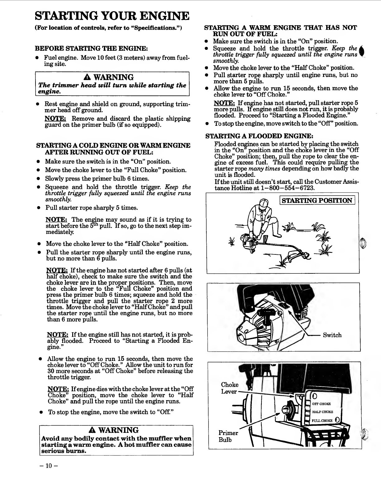
STARTING
A
FLOODED
ENGINE:
Flooded
engines
can
be
started
by
placing
the
switch
in
the
“On”
position
and
the
choke
lever
in
the
“Off
Choke”
position;
then,
puU
the
rope
to
clear
the
en¬
gine
of
excess
fuel.
This
could
require
pulling
the
starter
rope
many
times
depending
on
how
badly
the
unit
is
flooded.
If
the
unit
still
doesn’t
start,
call
the
Customer
Assis¬
tance
Hotline
at
1—800—554—6723.
-
1
0
-

D.
OPERATING
INSTRUCTIONS
1.
B
ring
the
engine
to
cutting
speed
before
enter¬
ing
the
material
to
be
cut.
a.
Do
not
run
the
engine
at
a
higher
speed
than
necessary.
The
cutting
line
vdll
cut
effi¬
ciently
when
the
engine
is
run
at
less
than
full
throttle.
At
lower
speeds,
there
is
less
engine
noise
and
vibration.
The
cutting
line
will
last
longer
and
will
be
less
likely
to
“weld”
onto
the
spool.
b.
If
trinuner
head
does
not
turn
when
the
en¬
gine
is
in
operation,
make
sure
the
drive
shaft
housing
is
properly
seated
in
the
engine
shroud.
Refer
to
“Assembly—Drive
Shaft
Housing.”
2.
Alwa^
release
the
throttle
trigger
and
al¬
low
the
engine
to
return
to
iffie
speed
when
not
cutting.
3.
To
stop
engine:
a.
Release
the
throttle
trigger.
b.
Move
ignition
switch
to
the
“Off”
position.
USING
YOUR
TRIMMER
LegG^u^s
\
\
-
Face
Boots
Shield
Thrown
Object
1
A
warning-throws
objects
The
rapidly
moving
line
causes
objects
to
be
thrown
violently.
The
shield
will
not
provide
complete
protection
to
the
operator
or
others.
The
operator
must
wear
a
safety
face
shield
or
goggles.
Always
wear
heavy,
long
pants
and
boots.
Keep
others
at
least
30
feet
(10
meters)
away.
A
WARNING
-
HAZARD
ZONE
This
tool
wih
throw
objects
and
cut.
Keep
oth¬
ers
including
children,
animals,
bystand¬
ers
and
helpers
at
least
30
feet
(10
meters)
away
&om
the
operator
and
tool.
Stop
the
engine
if
you
are
approached.
A
WARNING
-
DAMAGED
TRIM¬
MER
HEAD
Trimmer
head
parts
that
are
chipped,
cracked
or
damaged
in
any
other
way
can
fly
apart
and
cause
serious
injury.
Do
not
use.
Replace
damaged
parts
before
using
the
tool.
A.
LINE
TRIMMER
SAFETY
1.
OPERATOR
a.
Always
we^
eye
protection
when
oper-
ating,
servicing,
or
performing
mainte¬
nance
on
yom-
unit.
See
“Accessories.”
b.
Always
wear
heavy,
long
pants,
boots,
and
gloves.
See
“Accessories.
”
Do
not
go
bare¬
foot
or
wear
sandsils,
jewelry,
short
pants,
loose
clothing,
or
clothing
with
loosely
hanging
ties,
straps,
or
tassels;
they
can
be
caught
in
moving
parts.
Secure
hair
so
it
is
above
shoulder
length.
Being
fully
covered
will
help
protect
you
from
pieces
of
toxic
plants
such
as
poison
ivy
thrown
by
the
trimmer
head
which
could
be
more
of
a
hazard
than
touching
the
plant
itself.
c.
Do
not
operate
this
tool
when
you
are
tired,
ill
or
under
the
influence
of
alco¬
hol,
drugs
or
medication.
d.
Do
not
swing
unit
with
such
force
that
you
are
in
danger
of
losing
your
balance.
e.
Never
start
or
run
the
engine
inside
a
closed
room
or
building.
Breathing
exhaust
fumes
can
kill.
f.
Keep
handles
free
of
oil
and
fuel.
2.
TOOL
a.
Inspect
the
entire
tool
before
each
use.
Replace
damaged
parts.
Check
for
fuel
leaks
and
make
sure
aU
fasteners
are
in
place
and
se¬
curely
fastened.
b.
Use
only
.080”
diameter
WEED
LINE
brand
line.
Never
use
wire,
rope,
string,
etc.
c.
Be
sure
the
shield
is
properly
attached.
d.
Make
sure
the
trimmer
head
is
properly
installed
and
securely
fastened.
Refer
to
“Assembly.”
e.
Make
carburetor
adjustments
with
drive
shaft
housing
supported
to
prevent
the
trimmer
line
fl:om
contacting
any
object.
f.
Keep
others
away
when
making
carbure¬
tor
adjustments.
g.
Use
only
genuine
WEED
EATER
accesso¬
ries
or
attachments
as
recommended.
-
11
-

3.
CUTTING
a.
Inspect
the
area
to
be
cut
before
each
use.
Remove
objects
(rocks,
broken
glass,
nails,
wire,
string,
etc.)
which
can
be
thrown
or
become
entangled
in
the
trimmer
head.
b.
Always
keep
the
engine
on
the
right-
hand
side
of
your
body.
c.
Hold
the
tool
firmly
with
both
hands.
d.
Keep
firm
footing
and
balance.
Do
not
over-reach.
e.
Keep
the
trimmer
head
below
waist
level.
B.
TRIMMER
LINE
ADVANCE
•
The
trimmer
line
will
advance
approxi¬
mately
2
inches
each
time
the
bottom
of
the
trimmer
head
is
tapped
on
the
ground
with
the
engine
running
at
hill
throttle.
•
The
most
eHicient
line
length
is
the
maxi¬
mum
length
allowed
by
the
line
limiter.
•
Always
keep
the
shield
in
place
when
the
tool
is
being
operated.
•
To
Advance
Line:
1.
Operate
the
engine
at
full
throttle.
2.
Hold
the
trimmer
head
parallel
to
and
above
the
grassy
area.
3.
Tap
the
bottom
of
the
trimmer
head
hghtly
on
the
ground
one
time.
Approximately
2
inches
of
line
will
be
advanced
with
each
tap.
NOTE:
Always
tap
the
trimmer
head
on
a
grassy
area.
Tapping
on
surfaces
such
as
concrete
or
asphalt
can
cause
excessive
wear
to
the
trim¬
mer
head.
NOTE:
If
the
line
is
worn
down
to
two
inches
or
less,
more
than
one
tap
will
be
re¬
quired
to
obtain
the
most
efficient
line
length.
A
WARNING
Use
only
.080"
ffiameter
WEED
LINE
brand
line.
Other
sizes
of
line
will
not
advance
properly
and
can
cause
serious
injury.
Do
not
use
other
mate¬
rials
such
as
wire,
string,
rope,
etc.
Wire
can
break
off
during
cutting
and
become
a
danger-
ous
missile
that
can
cause
serious
ipjury.
f.
Do
not
raise
the
engine
above
your
waist.
g.
Keep
all
parts
ofyour
body
away
hrom
the
trimmer
line
when
the
engine
is
running.
h.
Keep
all
parts
of
your
body
away
foom
a
hot
muffler.
i.
Use
this
unit
only
for
jobs
explained
in
|
this
manual.
_
A
WARNING
Avoid
any
contact
with
a
hot
muffler.
A
hot
muffler
can
cause
serious
burns.
C.
CUTTING
METHODS
A
WARNING
Use
minimum
speed
and
do
not
crowd
the
line
when
cutting
around
hard
objects
(rock,
gravel,
fence
posts,
etc),
which
can
damage
the
trimmer
head,
become
entangled
in
the
line,
or
be
thrown
causing
a
serious
hazard._
•
The
tip
of
the
line
does
the
cutting.
You
will
achieve
the
best
performance
and
minimum
line
wear
by
not
crowding
line
into
the
cutting
area.
The
right
and
wrong
ways
are
shown
below.
•
The
line
will
easily
remove
grass
and
weeds
from
around
walls,
fences,
trees
and
flower
beds,
hut
it
also
can
cut
the
tender
hark
of
trees
or
shruhs
and
scar
fences.
To
help
avoid
d^age
especially
to
delicate
vegetation
or
trees
with
tender
bark,
shorten
line
to
4-5
inches
and
use
at
less
than
full
throttle.
•
For
trimming
or
scalping,
use
less
than
full
throttle
to
increase
line
life
and
decrease
’
head
wear,
especially:
-
during
light
duty
cutting.
-
near
objects
around
which
the
line
can
wrap
such
as
small
posts,
trees
or
fence
wire.
•
For
mowing
or
sweeping,
use
full
throttle
for
a
good
clean
job._
Tip
of
the
Line
Line
Crowded
Into
Does
The
Cutting
Work
Area
RIGHT
Ground
WRONG
A
WARNING
Always
wear
eye
protection.
Never
lean
over
the
trimmer
head.
Rocks
or
debris
can
ricochet
or
be
thrown
into
eyes
and
face
and
cause
blind¬
ness
or
other
serious
injury.
I
-
1
2
-

1.
TRBMMING
—
Hold
the
bottom
of
the
trimmer
head
about
3
inches
above
the
ground
and
at
an
angle.
Allow
only
the
tip
of
the
line
to
msike
con¬
tact.
Do
not
force
the
trimmer
line
into
the
work
area.
2.
SCALPING
—
The
scalping
technique
removes
unwanted
vegetation.
Hold
the
bottom
of
the
trimmer
head
about
3
inches
above
the
ground
and
at
an
angle.
Allow
the
tip
of
the
line
to
strike
the
ground
around
trees,
posts,
monuments,
etc.
This
technique
increases
line
wear.
3.
MOWING-
Your
trimmer
is
ideal
for
mowing
in
places
conventional
lawn
mowers
cannot
reach.
In
the
mowing
position,
keep
the
line
parallel
to
the
ground.
Avoid
pressing
the
head
into
the
ground
as
this
can
scalp
the
ground
and
damage
the
tool.
4.
SWEEPING
-
The
fanning
action
of
the
rotat¬
ing
line
can
be
used
for
a
quick
and
easy
clean
up.
Keep
the
hne
parallel
to
and
above
the
surfaces
be¬
ing
swept
and
move
the
tool
from
side
to
side.
D.
LINE
REPLACEMENT
•
For
proper
line
feed:
-
Use
only
genuine
WEED
ElATER
pre-
wound
spools
and
.080”
diameter
WEED
LINE
brand
line.
Use
of
other
types
of
spools
or
lines
can
result
in
excessive
breakage,
line
welding
and
improper
line
feed.
—
Pre—wound
spools
offer
the
most
conven¬
ient
method
for
replacing
line
as
well
as
optimum
performance.
*
Always
clean
dirt
and
debris
from
the
spool
and
hub
when
performing
any
type
mainte¬
nance.
1.
Installing
Spool
w/Line
a.
Hold
the
trimmer
head
as
shown.
Press
the
two
lock
tabs
and
remove
the
cover.
b.
Remove
the
spool.
c.
Clean
dirt
and
debris
from
all
parts.
d.
Inspect
all
trimmer
head
parts
for
damage.
Re¬
place
damaged
parts.
A
WARNING
Trimmer
head
parts
that
are
chipped,
cracked
or
damaged
in
any
way
can
fly
apart
and
cause
serious
injury.
Do
not
use.
Replace
damaged
parts
before
using
the
tool.
-
13
-
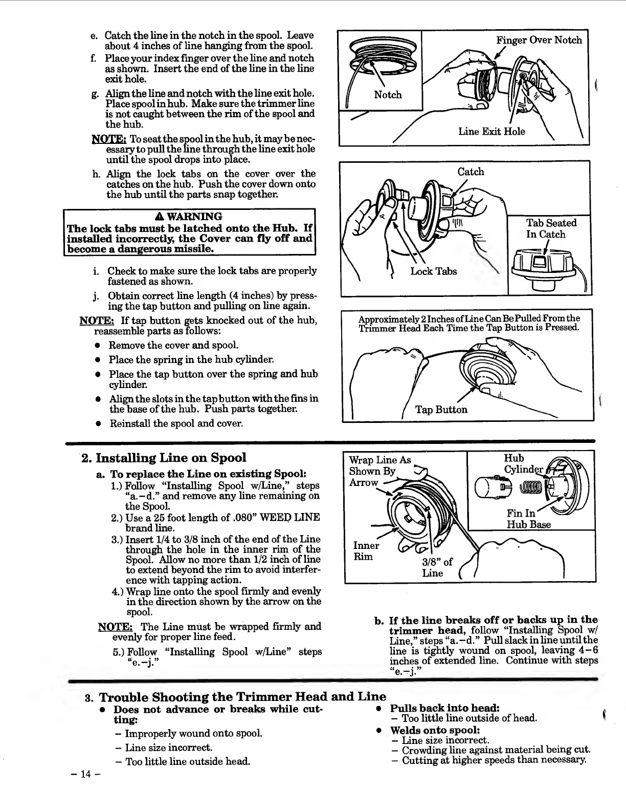
e.
Catch
the
line
in
the
notch
in
the
spool.
Leave
about
4
inches
of
line
hsinging
from
the
spool.
f.
Place
yom:
index
finger
over
the
line
and
notch
as
shown.
Insert
the
end
of
the
line
in
the
line
exit
hole.
g.
Align
the
line
and
notch
with
the
line
exit
hole.
Place
spool
in
hub.
Make
sure
the
trimmer
line
is
not
caught
between
the
rim
of
the
spool
and
the
hub.
NOTE;
To
seat
the
spool
in
the
hub,
it
may
be
nec¬
essary
to
pull
the
fine
through
the
Une
exit
hole
until
the
spool
drops
into
place.
h.
Align
the
lock
tabs
on
the
cover
over
the
catches
on
the
hub.
Push
the
cover
down
onto
the
hub
until
the
parts
snap
together.
A
WARNING
The
lock
tabs
must
be
latched
onto
the
Hub.
If
installed
incorrectly,
the
Cover
can
fly
off
and
become
a
dangerous
missile._
i.
Check
to
meike
sure
the
lock
tabs
are
properly
fastened
as
shown.
j.
Obtain
correct
line
length
(4
inches)
by
press¬
ing
the
tap
button
and
pulling
on
line
again.
NOTE:
If
tap
button
gets
knocked
out
of
the
hub,
reassemble
parts
as
follows;
•
Remove
the
cover
emd
spool.
•
Place
the
spring
in
the
hub
cylinder.
•
Place
the
tap
button
over
the
spring
and
hub
cylinder.
•
Align
the
slots
in
the
tap
button
with
the
fins
in
the
base
of
the
hub.
Push
parts
together.
•
Reinstall
the
spool
and
cover.
Approximately
2
Inches
of
Line
Can
Be
Pulled
From
the
Trimmer
Head
Each
Time
the
Tap
Button
is
Pressed.
2.
Installing
Line
on
Spool
a.
To
replace
the
Line
on
existing
Spool:
1.
)
FoUow
“Installing
Spool
w/Line,”
steps
“a.—d.”
and
remove
any
line
remaining
on
the
Spool.
2.
)
Use
a
25
foot
length
of
.080”
WEED
LINE
brand
line.
3.
)
Insert
1/4
to
3/8
inch
of
the
end
of
the
Line
through
the
hole
in
the
iimer
rim
of
the
Spool.
Allow
no
more
than
1/2
inch
of
line
to
extend
beyond
the
rim
to
avoid
interfer¬
ence
with
tapping
action.
4.
)
Wrap
line
onto
the
spool
firmly
and
evenly
in
the
direction
shown
by
the
arrow
on
the
spool.
NOTE;
The
Line
must
be
wrapped
firmly
and
evenly
for
proper
line
feed.
5.
)
Follow
“Installing
Spool
w/Line”
steps
“e.-j.”
b.
If
the
line
breaks
off
or
backs
up
in
the
trimmer
head,
follow
“Installing
Spool
w/
Line,”
steps
“a.
-d.”
Pull
slack
in
Une
until
the
Une
is
tightly
wound
on
spool,
leaving
4-6
inches
of
extended
Une.
Continue
with
steps
3.
Trouble
Shooting
the
Trimmer
Head
and
Line
•
Does
not
advance
or
breaks
while
cut-
•
ting:
-
Improperly
wound
onto
spool.
•
—
Line
size
incorrect.
-
Too
little
Une
outside
head.
Pulls
back
into
head:
-
Too
little
Une
outside
of
head.
Welds
onto
spool:
-
Line
size
incorrect.
-
Crowding
Une
against
material
being
cut.
-
Cutting
at
higher
speeds
than
necessary.
I
-
14
-

GENERAL
MAINTENANCE
A.
MAINTENANCE
SAFETY
1.
Maintain
unit
according
to
recommended
procedures.
Keep
cutting
fine
at
proper
length.
2.
Disconnect
spark
plug
before
performing
maintenance
except
carburetor
adjustments.
3.
Make
carburetor
adjustments
with
drive
shaft
housing
supported
to
prevent
the
trimmer
line
&om
contacting
any
object.
4.
Keep
others
away
when
making
carburetor
adjustments.
5.
Replace
trimmer
head
parts
that
are
cracked,
chipped
or
damaged
before
using
the
unit.
6.
Use
only
.080”
diameter
WEED
LINE
brand
line.
Never
use
wire,
rope,
string,
etc.
7.
Use
only
genuine
WEED
EATER
replace¬
ment
pails.
Use
of
other
brands
of
replacement
parts
can
cause
damage
to
your
unit
or
injury
to
the
operator
or
others.
Your
warranty
does
not
cover
damage
or
liability
caused
by
the
use
of
ac¬
cessories
and/or
attachments
not
specifically
rec¬
ommended
by
WEED
EATER.
8.
Inspect
the
entire
unit.
Replace
damaged
parts.
Check
for
fuel
leaks
and
make
sure
all
fas¬
teners
are
in
place
and
securely
fastened.
B.
AIR
FILTER
NOTE:
A
dirty
air
filter
decreases
the
fife
and
performance
of
the
engine
and
may
increase
fuel
consumption
and
hEumful
emissions.
1.
C
lean
the
Air
Filter:
•
Always
after
5
tanks
of
fuel
or
5
hours
of
operation,
whichever
is
less.
•
More
frequently,
in
dusty
conditions.
a.
Loosen
the
two
screws
on
the
air
filter
cover
enough
to
remove
the
cover
from
engine.
b.
Remove
the
air
filter
from
the
cover.
c.
Wash
filter
in
soap
and
water.
_
d.
Sque
eze
filter
dry
and
replace
in
cover.
1
CAUTION:
I
Do
not
clean
the
air
filter
in
gaso¬
line
or
any
other
flammable
solvent;
doing
so
may
create
a
fire
hazard
or
produce
harmf^
evaporative
emissions.
e.
Reinstall
the
air
filter
cover,
making
sure
the
choke
exit
slot
is
placed
over
the
choke
lever.
I
CAUTION:
I
Make
sure
the
air
filter
is
fitted
into
the
comers
of
the
cover
to
keep
dust
from
entering
the
engine
and
causing
en¬
gine
damage.
NOTE:
If
replacing
the
air
filter,
see
the
Accessory
List
for
proper
part
number.
C.
DRIVE
SHAFT
LUBRICATION
•
Lubricate
the
Drive
Shaft:
-
After
each
ten
(10)
hours
of
operation.
—
Before
operating
if
the
unit
has
been
stored
for
90
days
or
longer.
•
See
the
Accessory
List
for
flex
shaft
lube
part
number.
A
WARNING
If
the
engine
is
hot,
avoid
touching
the
muffler.
A
hot
muffler
can
cause
serious
bums.
I
CAUTI
ON:
I
Lay
the
drive
shaft
on
a
clean
sur¬
face.
Avoid
laying
the
shaft
on
the
floor,
ground,
or
on
any
other
smrface
that
may
have
dirt
or
debris.
Even
after
wiping
shaft,
grease
residue
can
pick
up
particles
that
can
cause
damage
or
premature
failure.
I
CAUTION:
I
Take
care
to
avoid
ipjuring
yotu*
hands
and
fingers
with
broken
wires
when
checking
for
damage
or
wiping
the
shaft.
A
cloth
will
not
prevent
broken
wires
from
puncturing
or
tearing
your
skin.
•
Use
the
following
procedure:
1.
Loosen
the
“nose
cone”
screws
and
remove
the
drive
shaft
housing
from
the
engine.
2.
Remove
drive
shaft
from
drive
shaft
housing.
3.
Check
the
drive
shaft
for
broken
wires,
twists
or
kinks,
and
replace
if
damage
is
found.
4.
Using
a
clean
cloth,
wipe
the
drive
shaft
thor¬
oughly
to
remove
any
old
grease.
5.
Apply
a
uniform
coat
of
lube
to
the
entire
sur¬
face
of
the
drive
shaft.
6.
Inject
the
remaining
contents
of
the
tube
into
the
top
of
the
drive
shaft
housing.
7.
Replace
drive
shaft
in
the
drive
shaft
housing.
8.
Reassemble
drive
shaft
housing
to
the
engine.
Tighten
screws
securely.
-
1
5
-
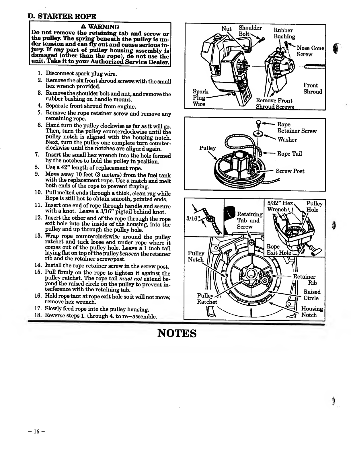
D.
STARTER
ROPE
A
WARNING
Do
not
remove
the
retaining
tab
and
screw
or
the
pulley.
The
sprii^
beneath
the
pulley
is
un¬
der
tension
and
can
fly
out
and
cause
serious
in¬
jury.
If
any
part
of
pulley
housing
assembly
is
damaged
(other
than
the
rope),
do
not
use
the
unit.
Tahe
it
to
your
Authorized
Service
Dealer.
1.
Disconnect
spark
plug
wire.
2.
Remove
the
six
front
shroud
screws
with
the
small
hex
wrench
provided.
3.
Remove
the
shoulder
bolt
and
nut,
and
remove
the
rubber
bushing
on
handle
mount.
4.
Separate
front
shroud
from
engine.
5.
Remove
the
rope
retainer
screw
and
remove
any
remaining
rope.
6.
Hand
turn
the
pulley
clockwise
as
far
as
it
will
go.
Then,
turn
the
pulley
counterclockwise
until
the
pulley
notch
is
aligned
with
the
housing
notch.
Next,
turn
the
pulley
one
complete
turn
counter¬
clockwise
until
the
notches
are
aligned
again.
7.
Insert
the
small
hex
wrench
into
the
hole
formed
by
the
notches
to
hold
the
pulley
in
position.
8.
Use
a
42”
length
of
replacement
rope.
9.
Move
away
10
feet
(3
meters)
from
the
fuel
tank
with
the
repleicement
rope.
Use
a
match
and
melt
both
ends
of
the
rope
to
prevent
fray
ing
10.
Pull
melted
ends
through
a
thick,
clean
reig
while
Rope
is
still
hot
to
obtedn
smooth,
pointed
ends.
11.
Insert
one
end
of
rope
through
handle
and
secure
with
a
knot.
Leave
a
3/16”
pigtail
behind
knot.
12.
Insert
the
other
end
of
the
rope
through
the
rope
exit
hole
into
the
inside
of
the
housing,
into
the
pulley
and
up
through
the
pulley
hole.
13.
Wrap
rope
counterclockwise
around
the
pulley
ratchet
and
tuck
loose
end
under
rope
where
it
comes
out
of
the
pulley
hole.
Leave
a
1
inch
tail
l&^ngflat
on
top
of
the
pulley
between
the
retainer
rib
and
the
retainer
screw/post.
14.
Install
the
rope
retainer
screw
in
the
screw
post.
15.
Pull
firmly
on
the
rope
to
tighten
it
against
the
pulley
ratchet.
The
rope
tail
must
not
extend
be¬
yond
the
reused
circle
on
the
pulley
to
prevent
in¬
terference
with
the
retaining
tab.
16.
Hold
rope
taut
at
rope
exit
hole
so
it
will
not
move;
remove
hex
wrench.
17.
Slowly
feed
rope
into
the
pulley
housing.
18.
Reverse
steps
1.
through
4.
to
re-assemble.
Nut
Shoulder
Bolt
Rubber
Bushing
Nose
Cone
1
Screw
Spark
Plug
Wire
Front
Shroud
Remove
Front
Shroud
Screws
—
Rope
NOTES
i
-
16
-
E.
CARBURETOR
ADJUSTMENTS
YOUR
WEED
EATER
PRODUCT
HAS
BEEN
DESIGNED
AND
MANUFACTURED
TO
SPECIFI¬
CATIONS
THAT
REDUCE
HARMFUL
EMISSIONS.
After
your
unit
has
been
run
for
6
hours,
the
en¬
gine
has
broken-in.
To
ensure
that
yoiur
unit
is
at
peak
performance
and
producing
the
least
amount
of
harmful
emissions
after
break-in,
have
your
Authorized
Service
Dealer
adjust
yoiur
carburetor
for
optimum
operating
conditions.
NOTE;
Properly
adjusting
the
carburetor
is
a
complicated
task.
Read
all
warnings
and
instructions
thoroughly
before
starting
adjustments.
If
you
do
not
think
that
you
completely
understand
all
warn¬
ings
and
instructions,
let
your
Authorized
Service
Dealer
perform
these
adjustments.
A
WARNING
Make
carburetor
adjustments
with
the
drive
shaft
housing
supported
to
prevent
the
trimmer
line
from
contacting
any
object.
Hold
the
unit
with
your
hand;
do
not
use
the
optional
shoulder
strap
for
support._
A
WARNING
Keep
others
away
when
making
carburetor
ad-
justments.
_
7^
A
WARNING
Serious
injury
to
the
operator
and
others
can
oc¬
cur
if
the
carburetor
is
not
properly
adjusted.
•
Poor
engine
performance
can
be
a
result
of
other
causes
such
as
dirty
air
Hlter,
carbon
build-up
on
muffler
outlets,
etc.
See
“Trouble
Shooting
Chart”
before
proceed¬
ing
with
carburetor
adjustments.
•
For
best
results,
it
is
recommended
that
you
have
an
Authorized
Service
Dealer
make
all
carburetor
adjustments.
Your
dealer
has
the
training,
experience,
and
tools
necessary
to
prop¬
erly
adjust
your
unit
to
meet
our
factory
perform¬
ance
specifications.
This
service
is
not
covered
by
warranty.
If
it
becomes
necessary
for
you
to
make
carburetor
adjustments
yoursefr,
follow
the
de¬
scribed
procedures
very
carefully.
•
Very
small
adjustments
can
afreet
engine
performance.
It
is
important
to
turn
the
screw
a
very
small
amount
per
adjustment
and
test
per¬
formance
before
making
further
adjustments.
Each
adjustment
should
be
no
more
than
the
width
of
the
slot
in
the
adjusting
screw.
•
This
is
a
complicated
task
and
it
is
impor¬
tant
to
follow
instructions
in
sequence
as
indicated.
2.
BASIC
CARBURETOR
SETTINGS
NOTE:
In
most
cases,
your
engine
can
be
made
to
run
properly
with
minor
carburetor
adjustments.
Refer
to
“Trouble
Shooting
Suggestions”
in
the
left
column
for
the
condition
you
are
experiencing
and
follow
the
instructions.
The
basic
carburetor
settings
are
provided
below.
a.
T
urn
the
mixture
screw
to
the
mid
point.
Do
not
attempt
to
adjust
the
screw
beyond
the
stops
as
damage
can
occur.
3.
ADJUSTING
PROCEDURE
a.
PREPARATION
1.
Use
a
fresh
fuel
mix.
See
“Fuehng
Your
En-
^
110
.
2.
Make
sure
the
line
extends
to
the
length
al¬
lowed
by
the
line
limiter
to
provide
correct
load
on
engine.
3.
Steurt
the
engine.
Cut
grass
for
3
minutes
to
warm
engine.
The
engine
must
be
at
operat¬
ing
temperature
before
carburetor
adjust¬
ments
can
be
performed
correctly.
b.
IDLE
SPEED
ADJUSTMENT
1.
Allow
engine
to
idle;
be
sure
the
trimmer
line
is
extended
to
maximum
length
al¬
lowed
by
the
line
hmiter.
2.
Adjust
idle
speed
screw
until
engine
contin¬
ues
to
run
without
stalling.
-
Turn
screw
clockwise
to
increase
engine
speed
if
the
engine
stalls
or
dies.
-
Turn
screw
counterclockwise
to
slow
en¬
gine
down.
3.
Follow
instructions
in
“Acceleration
Check”
and
“Deceleration
Check.”
4.
No
further
adjustments
are
necessary
if
performance
is
satisfactory.
1.
T
ROUBLE
SHOOTING
SUGGESTIONS
-
Engine
will
not
continue
to
run
at
idle
posi¬
tion.
See
“Idle
Speed
Adjustment”
and
“Mix¬
ture
Adjustment.”
-
Engine
dies
or
hesitates
when
it
should
accel¬
erate.
See
“Acceleration
Check.”
—
Loss
of
cutting
power
which
cannot
be
cor¬
rected
by
cleaning
the
air
filter.
See
“Mixture
Adjustment.”
-
Engine
does
not
return
to
idle
from
full
throt¬
tle
within
2
seconds.
See
“Deceleration
Check.”
-
Engine
will
not
run.
See
“Trouble
Shooting
Chart.”
Then,
if
carburetor
requires
adjust¬
ment,
begin
with
“Basic
Carburetor
Settings.”
A
WARNING
The
trimmer
head
will
be
spinning
during
this
procedure.
Wear
your
protective
equipment
and
observe
all
sEtfety
instructions.
c.
A
CCELERATION
CHECK
1.
Allow
engine
to
idle;
be
sure
the
trimmer
line
is
extended
to
maximum
length
al¬
lowed
by
the
line
limiter.
2.
Squeeze
trigger
fully
a.
If
performance
is
satisfactory,
pro¬
ceed
to
“d.
Deceleration
Check.”
b.
If
the
engine
does
not
accelerate
smoothly,
turn
the
mixture
screw
counterclockwise
a
small
amount
(no
more
than
the
width
of
the
slot
in
the
ad¬
justing
screw).
3.
Repeat
st^
“2.”
until
smooth
acceleration
4.
Do
not
attempt
to
adjust
the
screw
beyond
the
stops
as
damage
can
occur.
NOTE:
It
may
be
necessary
to
repeat
“Idle
Speed
Adjustment”
through
“Acceleration
Check,”
to
obtain
correct
adjustments.
5.
Follow
instructions
in
“Deceleration
Check.”
-
1
7
-

d.
DECELERATION
CHECK
1.
^ow
engine
to
idle;
be
sure
the
trimmer
line
is
emended
to
maximum
length
al¬
lowed
by
the
line
Umiter.
2.
Squeeze
throttle
trigger
fully.
3.
Allow
engine
to
run
at
full
speed
for
about
1
second.
4.
Release
the
throttle
trigger
to
the
idle
posi¬
tion
and
listen
to
the
deceleration
of
the
en¬
gine.
It
must
retirni
to
idle
smoothly
within
1
to
2
seconds.
a.
If
performance
is
satisfactory,
no
further
adjustments
are
neccessary.
b.
If
the
engine
slowly
or
erratically
returns
to
idle
or
idles
erratically,
proceed
to
“Mixture
Adjustment.”
e.
MIXTU
RE
ADJUSTMENT
I
CAUTION;
i
Do
not
operate
engine
at
full
throttle
for
prolonged
periods
while
mak¬
ing
mixture
adjustments
as
damage
to
the
engine
can
occur.
1.
Support
the
drive
shaft
housing
so
the
trim-
|
mer
head
is
off
the
ground
and
the
line
will
not
make
contact
with
any
object.
2.
Start
the
engine;
be
sure
the
trimmer
line
is
extended
to
maximum
length
allowed
by
the
line
limiter.
Allow
enmne
to
idle,
then
squeeze
throttle
trigger
fully.
NOTE;
Perform
steps
“3.”
through
“5.,”
at
full
throttle.
3.
Turn
mixture
screw
very
slowly
clockwise
until
engine
speed
is
reduced.
4.
Turn
mixture
screw
very
slowly
counter¬
clockwise.
Stop
when
the
engine
begins
to
nm
roughly.
5.
Turn
the
screw
slowly
the
mi
nim
um
amoimt
clockwise
until
the
engine
runs
smoothly.
6.
Do
not
attempt
to
adjust
the
screw
heyond
the
stops
as
dameige
can
occur.
7.
FoUow
instructions
in
’’Acceleration
Check”
and
’’Deceleration
Check”.
I
CAUTION;
I
If
the
engine
does
not
operate
ac¬
cording
to
these
instructions
after
repeat¬
ing
the
adjusting
steps,
do
not
use
the
unit.
Take
it
to
your
Authorized
Service
Dealer.
F.
SPARK
PLUG
R
eplace
the
spark
plug
yearly.
NOTES
I

G.TROUBLE
SHOOTING
CHART
SYMPTOM
CAUSE
REMEDY
jEngine
will
not
p
start
or
will
run
only
for
a
few
seconds
after
starting.
1.
Fuel
tank
empty.
2.
Engine
flooded.
3.
Spark
plug
not
firing.
4.
Fuel
not
reaching
carburetor.
5.
Carburetor
requires
ac^ustment.
6.
None
of
the
above.
1.
Fill
tank
with
correct
fuel
mixture
2.
See
“Starting
Instructions.”
3.
Install
new
plug/check
ignition
system.
4.
Clean
fuel
filter;
inspect
fuel
line.
5.
See
“Carburetor
Adjustments.”
6.
Contact
your
Authorized
Service
Dealer.
Enrine
will
not
idle
properly.
1.
Idle
speed
set
too
fast
or
too
slow.
2.
Carburetor
requires
adjustment.
3.
None
of
the
above.
1.
See
“Carburetor
Adjustments.”
2.
See
“Carburetor
Adjustments.”
3.
Contact
your
Authorized
Service
Dealer.
Engine
will
not
accelerate,lacks
power,
or
^es
under
a
load.
1.
Air
filter
dirty.
2.
Spark
plug
fouled.
3.
Carburetor
requires
adjustment.
4.
Muffler
outlets
plugged.
5.
None
of
the
above.
1.
Clean
or
replace
air
filter.
2.
Clean
or
replace
spark
plug
and
re-gap.
3.
See
“Carburetor
Adjustments.”
4.
Contact
your
Authorized
Service
Dealer.
5.
Contact
your
Authorized
Service
Dealer.
Engine
smokes
excessively.
1.
Air
filter
dirty.
2.
Fuel
mixture
incorrect.
3.
Carburetor
requires
adjustment.
1.
Clean
or
replace
air
filter.
2.
See
“FueUng
Your
Unit.”
3.
See
“Carburetor
Adjustments.”
Engine
runs
hot.
1.
Fuel
mixture
incorrect.
2.
Carburetor
set
too
low
(lean).
3.
Spark
plug
incorrect.
4.
None
of
the
above.
1.
See
“Fueling
Your
Unit.”
2.
See
“Carburetor
Adjustments.”
3.
Replace
with
correct
plug.
4.
Contact
your
Authorized
Service
Dealer
Cutting
Head
stops
^
under
a
load
or
1
does
not
turn
when
engine
is
accelerated.
1.
Drive
shaft
broken.
2.
Drive
shaft
not
engaged.
1.
Contact
your
Authorized
Service
Dealer.
2.
Replace
or
see
“Assembly”.
Line
does
not
advance
or
breaks
while
cutting.
1.
Line
improperly
routed
in
bead.
2.
Line
improperly
wound
onto
spool.
3.
Line
size
incorrect.
4.
Too
little
line
outside
head.
5.
Dirt
accumulated
on
cover
cut-outs.
1.
Remove
cover.
Check
line
routing.
2.
Rewind
line
tightly
and
evenly.
3.
Use
only
.080”
dia.
WEED
LINE
brand
line.
4.
Remove
cover.
Pull
4”
of
line
to
outside.
5.
Clean
cover
cut-outs.
Line
welds
on
spool.
1.
Line
size
incorrect.
2.
Incorrect
spool.
3.
Crowding
bne
against
material
being
cut.
4.
Cutting
at
higher
speed
than
necessary.
1.
Use
only
.080”
dia.
WEED
LINE
brand
line.
2.
Use
proper
spool.
3.
Cut
with
tip
of
line.
4.
Reduce
cutting
speed.
Line
releases
continuously.
1.
Tap
Button
engaged.
1.
Remove
and
clean
Tap
Button.
Line
usage
is
excessive.
1.
Line
size
incorrect.
2.
Cutting
at
high
speed
around
hard
objects.
3.
Crowding
line
against
material
being
cut.
1.
Use
only
.080”
dia.
WEED
LINE
brand
line.
2.
Reduce
speed
around
hard
objects.
3.
Cut
with
tip
of
bne.
Line
pulls
back
into
head.
1.
Too
little
line
outside
of
head.
1.
Remove
cover.
Pull
4”
of
line
to
outside.
-
1
9
-
CUSTOMER
ASSISTANCE
^
call
1-800-554-6723
■
One
of
the
most
important
priorities
at
POULAN/WEED
EATER
is
customer
satisfaction,
especially
after
the
sale.
Your
product
has
been
expertly
engineered
and
carefully
manufactured
to
rigid
quality
stwdards
to
provide
you
with
optimum
performance
and
maximum
operational
lifetime.
^
with
ml
mechanical
products,
however,
making
adjustments
or
replacing
parts
may
he
necessarv
during
the
life
of
your
unit.
Because
customer
satisfaction
is
a
m^'or
priority,
POULAN/WEED
EATER
has
established
a
special,
toll
free
Customer
Assistance
Service
to
assist
you
with
any
after—the—sale
needs.
Whether
you
need
a
replacement
part,
an
accessory,
the
name
of
your
nearest
sales
or
service
dealer,
or
just
need
help
in
assembling
your
unit,
our
customer
service
representatives
will
be
available
to
answer
your
questions.
When
calling
our
Customer
Assistance
Service,
please
be
prepared
to
give
the
description
of
the
unit,
the
model
number,
serial
number,
and,
if
ordering
parts,
the
part
number
or
description
of
each
part.
Call
1—800—554—6723.
Our
representatives
will
be
glad
to
help.
FOR
SERVICE
OR
REPLACEMENT
PARTS:
1.
Consult
your
dealer/place
of
purchase.
2.
Consult
the
yellow
pages
of
your
phone
directory
for
the
name
of
the
nearest
POULAN/WEED
EATER
Master
Service
Dealer
(under
“saws”
for
Chain
Saws
or
under
“lawnmowers”
for
Trimmers,
Brushcutters,
and
Blowers).
POULAN/WEED
EATER
Division
provides
parts
and
service
through
its
authorized
distributors
and
dealers;
therefore,
all
requests
for
parts
and
service
should
be
directed
to
your
local
dealer(s).
The
philosophy
of
POULAN/WEED
EATER
Division
is
to
continually
improve
all
of
its
products.
If
the
operating
characteristics
or
the
appearance
of
your
product
differs
from
those
described
in
this
Operator’s
Manual,
please
contact
your
local
POULAN/WEED
EATER
Dealer
for
updated
information
and
assistance.
POULANAVEED
EATER
DIVISION
OF
WCI
OUTDOOR
PRODUCTS,
INC.
Shreveport,
Louisiana
71129
U.S.A.
530-081859-1-09/13/93
©1993
Poulan/Weed
Eater
Division
WCI
Outdoor
Products,
Inc.
Table of contents


