TrailFX W35B User manual
1
ATV / UTV Winch
Owner’s Manual
EnglishFrancaisEspañol
®

1

3
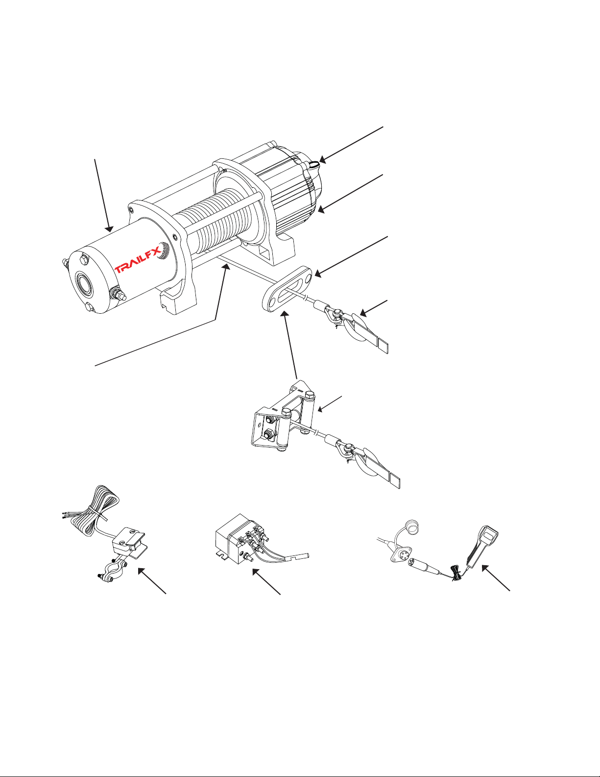
Key Winch Components
Part numbers : W35B and WS35B
Freespool Lever
Motor Housing
Gear Housing
Remote Control
Roller Fairlead ( Applicable for wire rope winch )
Hook
Forged hook designed to safely handle
rated winch load.
Rope
Fairlead
High strength Wire / Synthetic rope
designed to pull rated load safely. Always
remain within the rated load per layer as
specified in this manual and warning label.
Always replace the rope with exactly the
same type, length and rope strength as
specified in this manual.
Houses the series wound 12V
DC motor which drives the gear
system and ultimately driving
the drum.
Engages or Disengages the gear
drive system allowing operator to
pull the rated load or free spool
the rope.
Houses maintenance free 3-stage
planetary gear system that can be
either ‘Engaged’ or ‘Disengaged’ by
the operator.
High quality fairlead for guiding the
winch rope to and from the drum.
High quality roller fairlead for
guiding the winch rope to and
from the drum.
Allows the operator to control
the winch direction from a safe
distance.
Solenoid
Solenoid supplies power to the
motor via mini rocker switch /
remote control switch. Solenoid
meets IP67 for water resistance.
Mini Rocker Switch
Allows the operator to control
the winch direction from ATV
handlebar itself.
OUT IN
English
®
4
Key Winch Components
Part numbers : W45B and WS45B
Freespool Lever
Motor Housing
Gear Housing
Roller Fairlead ( Applicable for wire rope winch )
Hook
Forged hook designed to safely handle
rated winch load.
Rope
Fairlead
High strength Wire / Synthetic rope
designed to pull rated load safely. Always
remain within the rated load per layer as
specified in this manual and warning label.
Always replace the rope with exactly the
same type, length and rope strength as
specified in this manual.
Houses the series wound 12V
DC motor which drives the gear
system and ultimately driving
the drum.
Engages or Disengages the gear
drive system allowing operator to
pull the rated load or free spool
the rope.
Houses maintenance free 3-stage
planetary gear system that can be
either ‘Engaged’ or ‘Disengaged’ by
the operator.
High quality fairlead for guiding the
winch rope to and from the drum.
High quality roller fairlead for
guiding the winch rope to and
from the drum.
Remote Control
Allows the operator to control
the winch direction from a safe
distance.
OUT IN
Solenoid
Solenoid supplies power to the
motor via mini rocker switch /
remote control switch. Solenoid
meets IP67 for water resistance.
Mini Rocker Switch
Allows the operator to control
the winch direction from ATV
handlebar itself.
®

Safety Precautions
Observe safety precautions for personal safety and the safety of others.
Improper equipment operation may cause personal injur
Never operate this winch if you are under 16 years of age.
Never operate this winch when under the influence of drugs, alcohol or medication.
y and equipment damage.
Read the following carefully before attempting to operate your winch and keep the instructions
for future reference.
1. Dress Properly:
• Do not wear loose clothing or jewelry. They can be caught in moving parts.
• Wear proper winching gloves when handling the winch rope. Do not handle rope with bare hands as
broken strands can cause injuries.
• Non-skid footwear is recommended.
2. Keep a Safe Distance:
• Ensure that all persons stand clear of winch rope and load during winch operation,
1.5 times of the length of the rope is recommended. If a rope pulls loose or breaks under load,
it can lash back and cause serious injury or death.
• Do not step over the rope.
• All visitors and onlookers should be kept away from the work area.
• Keep proper footing and balance at all times.
3. Do Not Abuse Electrical Cables:
• Never carry your winch by the electrical cables or yank it to disconnect it from the receptacle.
• Keep electical cables from heat, oil and sharp edges.
4. Do Not Overwork the Winch:
• If the motor becomes uncomfortably hot to touch, stop and let it cool for a few minutes.
• Shut off power to the winch if the motor stalls.
Do not exceed maximum line pull ratings shown in tables.
Shock loads must not exceed these ratings.
5. Avoid Unintentional Starting:
• Winch clutch should be disengaged when not in use and fully engaged when in use.
6. Check Damaged Parts:
• Before using, you should check your winch carefully. Any part that is damaged should be
properly repaired or replaced. Technical support and replacement parts may be obtained by
contacting customer service as specified on the back cover of the manual or on the warranty card.
7. Repair Your Winch:
• When repairing, use only identical replacement parts or it may cause considerable danger to
the user. Replacement parts may be obtained from customer service as specified in
page number 16.
8. Re-spool the Rope:
• Winching gloves must be worn while re-spooling. It is necessary to maintain a slight load on the rope.
Hold the rope with one hand and the remote control switch with the other. Start as far back and in
the center as you can. Walk up keeping load on the rope as the winch is powered in.
• Do not allow the rope to slip through your hand and do not approach the winch too closely.
• Turn off the winch and repeat the procedure until all the rope is spooled except 3 ft.
• Disconnect the remote control switch and finish spooling in rope by rotating the drum by
hand with clutch disengaged.
• On hidden winches, spool in rope under power but keep hands clear.
5
English

Winch Operation Warnings
Read the following carefully before attempting to operate your winch and keep the instructions for
future reference.
1. The uneven spooling of rope,while pulling a load, is not a problem, unless there is rope stacked
up on one end of the drum. If this happens, reverse the winch to relieve the load and move your
anchor point further to the center of the vehicle. Once complete, you can unspool and rewind for
a more balanced lay of the rope.
2. Store the remote control switch inside your vehicle where it will not get damaged. Inspect it
before you plug in.
4. When ready to begin spooling in, plug in remote control switch or use handle bar rocker switch
with clutch disengaged. Do not engage clutch with motor running.
3. Turn ATV key switch to ON position. Check winch for proper operation. The rope should
spool in and out in the direction indicated on the rocker switch / remote control.
9. After winch use, always prepare your winch for storage. Inspect the installation, rope, rigging,
and accessories for any damage that may have occurred during use. Inspect the winch by
checking the tightness of mounting bolts and checking the winch for any loose
components or fasteners.
10. The solenoid is a primary safety feature in your winch system. It disconnects your winch from the
battery when the ATV is not in use. The solenoid must be correctly installed for the winch
to work properly.
5. Never connect the hook back to the rope as this causes rope damage. Always use a sling or
chain of suitable strength.
6. Observe your winch while winching if possible, standing at a safe distance. Stop the
winching process every meter or so to assure the rope is not pulling up in one corner.
Jamming the rope can break your winch.
7. Ensure "D" rated, or bow shackles are used in conjunction with an approved tree trunk protector
to provide a safe anchor point.
8. When extending the winch rope, ensure that at least five wraps of rope remain on the drum at all
times. Failure to do this could result in the rope parting from the drum under load. Serious
personal injury or property damage may result.
11. All winches are provided with a red marking on the rope which identifies
where (5) rope wraps remain on the winch drum. No recovery should be
attempted beyond this marking or serious injury may occur.
12. Since the maximum line pull is achieved on the first layer of the winch, it is desirable to pull off
as much line as you can for heavy pulls. Doubling or tripling snatch blocks can help. You
must leave at least five wraps minimum on the drum or see red rope NOT exposed!
13. Draping a heavy blanket or similar object over the extended winch rope is recommended as it
will dampen any back lash should a failure occur.
14. Neat, tight spooling avoids rope binding, which is caused when a load is applied and the rope
is pinched between the others. If this happens, alternatively power the winch in and out. Do not
attempt to work a bound rope under load, free by hand.
15. Apply blocks to wheels when vehicles are on an incline.
16. Battery:
• Be sure that the battery is in good condition. Avoid contact with battery acid or other contaminants.
.
a
y:
• Always wear eye protection when working around a battery.
• Have the engine running when using the winch, to avoid rapid degradation of the battery.
6
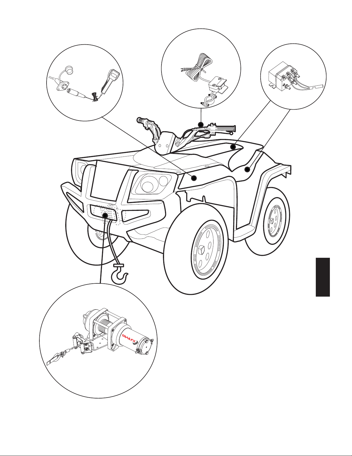
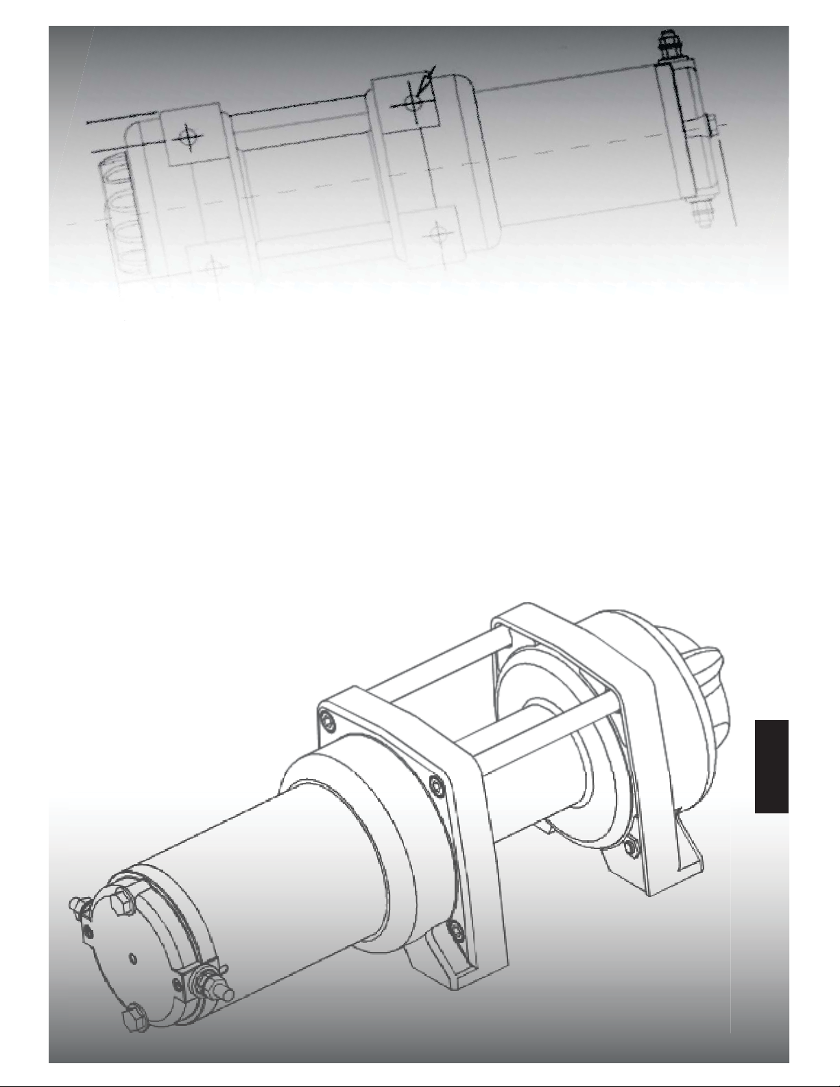
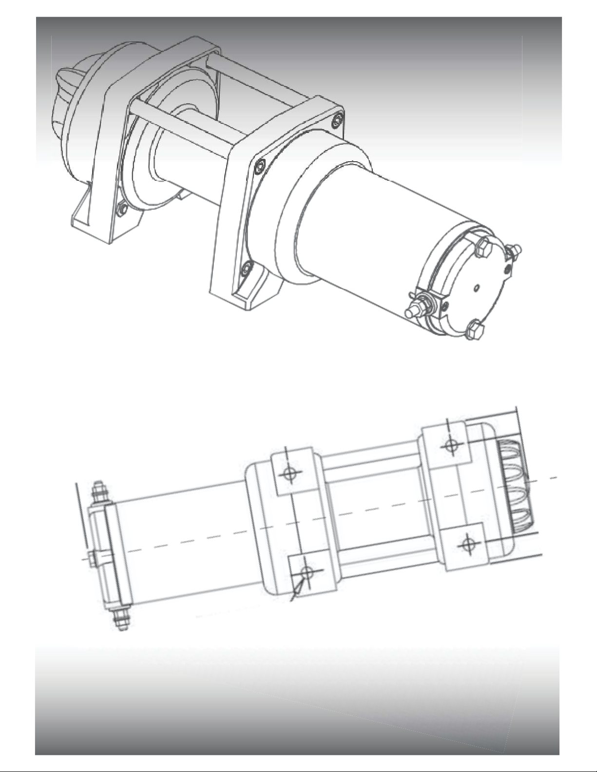
Solenoid
ATV Winch
Figure: 1
Mini Rocker Switch
To install an ATV winch, you need to mount the winch, solenoid, Handlebar Mini Rocker switch & Remote socket (female
Receiver). Winch & Accessory mounting locations may vary depending on your ATV/UTV Make/Model. Please read the ATV
Winch Kit mounting instructions provided on the next page.
Handled Remote
Control
OUT IN
ATV Winch Kit Mounting:
English
7
®
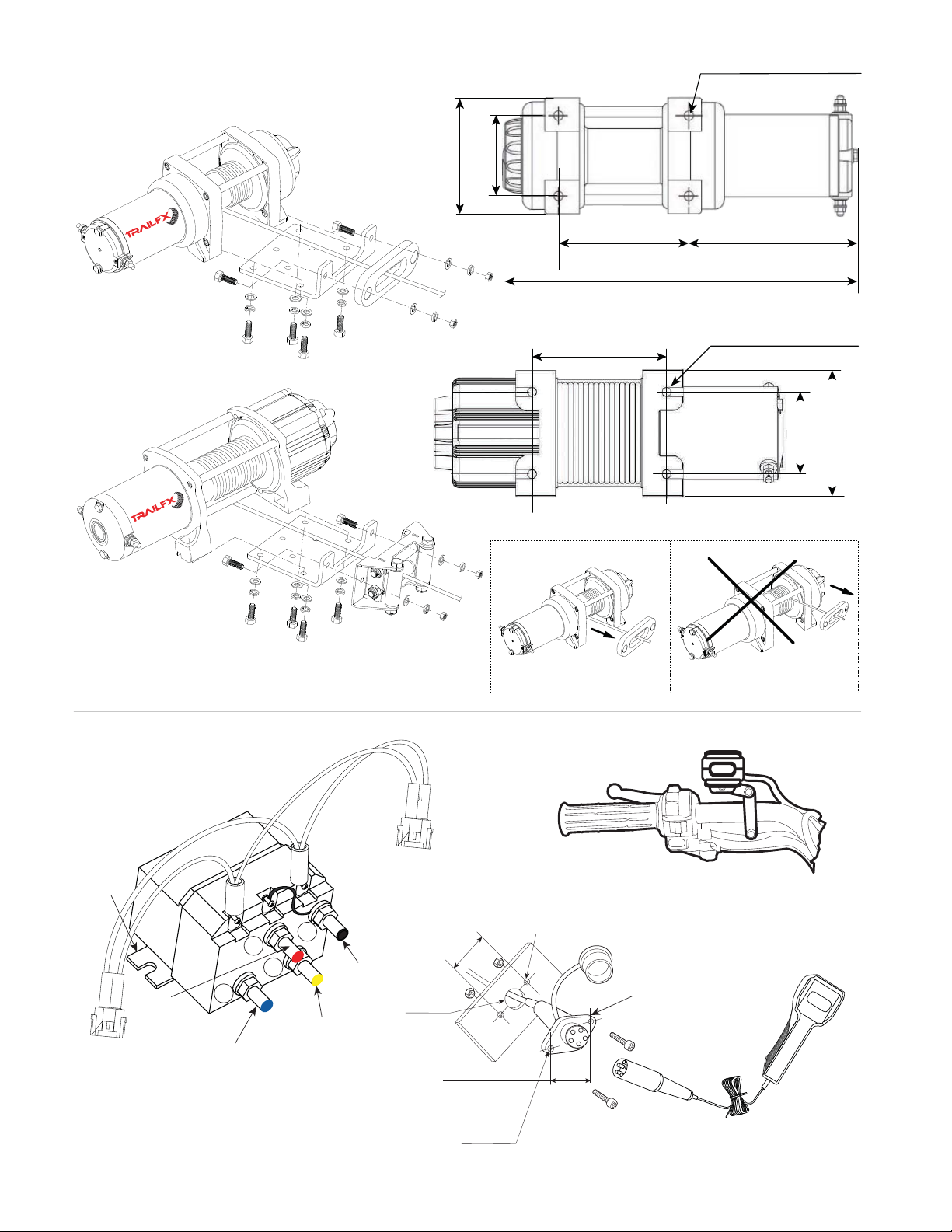
13.35” ( 339 mm )
4.88” ( 124 mm )
1.98” ( 50 mm )
3”( 76 mm )
4.88” ( 124 mm )
4.33” ( 110 mm )
3” ( 76 mm )
6.3” (160 mm )
4 x ø8 mm (Threaded)
4.62” ( 117 mm )
4 x ø8 mm (Threaded)
ø4.5 mm
1.98”(50 mm)
ø4.5 mm
ø19 mm
WINCH MOUNTING
W35B, WS35B
W45B, WS45B
CORRECT INCORRECT
Red
Terminal
Black Terminal
Remote Receiving
Socket
Solenoid Mounting
Blue Terminal
Mounting
Plate
Yellow Terminal
B+
M-
M+
B-
DOWN WIND TOP WIND
Handlebar Mini Rocker Switch
Handheld Remote Control
OUT IN
Figure: 2
Figure: 3
Figure: 4
Figure: 5
8
OUT IN
®
®

Winch Mounting:
1. To secure the winch, always use a flat, secure mounting location at least 3/16 inch (4.8 mm) thick.
2. 5/16-18 x 1 inch grade 5 hexagonal head cap screws and lock washer supplied with TrailFX
ATV/UTV Winch kit.
3. Torque mounting bolts to 12 lbs/ft (1.7 kg-m).
4. Attach roller fairlead / aluminium fairlead to winch mounting plate using 3/8-16 bolts, nuts and washers
5. Attach the clevis Hook to the rope.
6. Put the clutch in freespool position & manually feed cable loop through fairlead.
7. Attach hook to cable loop and re-engage the clutch.
8. Refer to figure No. 2 for the mounting pattern & dimensions.
9. After mounting, rope should be in the under wind direction as shown in the figure 2. Over-winding
the rope may damage the winch and void warranty.
Solenoid Mounting:
1. The solenoid disconnects the winch from the power source (Battery) when ATV is not in use.
2. The solenoid should be mounted on a safe, clean place close enough to the battery.
3. The solenoid can be placed under the seats, in the rear storage box, or as recommended by the ATV
manufacturer.
4. The solenoid should have enough clearance from other metal parts of the ATV to avoid direct contact,
which may lead to solenoid malfunction.
5. Drill mounting holes for the solenoid, however do not mount the solenoid until you attach all the
cables from the battery, handlebar mini rocker switch & remote control.
6. Cable colors should be matched with the contact terminal color codes (M+, M-, B+, B-) as shown in
the figure 3.
Handlebar Mini Rocker Switch Mounting:
1. Using the supplied black coated mounting clamp & screws, mount the mini rocker switch on the
handlebar.
2. A small piece of electrical tape could be used to avoid rotation of mini rocker switch cable after
mounting on the handlebar. (N0TE: It's recommended to mount this mini rocker switch on the left
side of the handlebar).
3. After mounting the mini rocker switch, route the cables to the place where the solenoid is
mounted. Connect the small red lead into the wire that electrifies with the ignition switch “ON”
and not electrifies with the ignition switch “OFF” as shown in the figure No 6. The wire
should only have power when the ATV/UTV key is in the “ON” position (Preferably fuse controlled).
Remote Control Socket Mounting:
1. Select a place to mount the remote control socket (female receiver).
2. Drill 3 holes as per the pattern & dimensions shown in the figure 5 and mount the socket.
3. After mounting the remote socket, route the cables to the place where the solenoid is mounted.
Connect the small red lead into the wire that electrifies with the ignition switch “ON”and not
electrifies with the ignition switch “OFF” as shown in the figure No 6. The wire should only
have power when the ATV/UTV key is in the “ON” position (Preferably fuse controlled).
4. Keep the remote socket closed with the built in cap when not in use.
9
English

OUT IN
Motor
Blue
Yellow
Black
Red
Positive Terminal (+) Positive Terminal (+)
Negative Terminal (-)
Red Terminal
Black Terminal
Solenoid
Blue Terminal
Yellow Terminal
Negative Terminal (-)
Remote
Receiver Socket
Small Red Cable
Handle Bar Mini Rocker Switch
ATV Ignition Key
Handheld
Remote Control
Electrical Connection:
10
B+B-
OUT IN
M+ M-
White Plastic Connector Green &
Black
Small Red Cable
Figure: 6
1. Please refer to Figure 6 while making electrical connections.
2. Connect one end of the “Yellow” cable to the positive (+) Terminal of the winch motor.
3. Connect the other end of the “Yellow” cable to the “Yellow Terminal marked as M+” on the solenoid.
4. Connect one end of the “Blue” cable to the negative (-) Terminal of the winch motor.
5. Connect the other end of the “Blue” cable to the “Blue Terminal marked as M-” on the solenoid.
6. Connect one end of the “Red” cable to the “Red terminal marked as B+” on the solenoid.
7. Connect one end of the “Black” cable to the “Black terminal marked as B-” on the solenoid.
8. There are 2 white plastic connectors provided from the solenoid.
9. Connect any one of the white plastic connectors with the black jacketed cable which is connected
to the handlebar mini rocker switch on the other end.
10. Connect the other white plastic connector with the black jacketed cable which is connected to the
remote receiver socket on the other end.
11. Make sure that the 2 small red cables coming from the handlebar mini rocker switch & handheld
remote control are connected to the ATV Ignition switch as stated under the handlebar mini
rocker switch mounting Instructions & remote control mounting instructions on the previous page.
12. Connect the loose end of the “Red” cable from the red terminal of solenoid to the positive (+) terminal
of the battery.
13. Connect the loose end of the “Black” cable from the black terminal of the solenoid to the negative (-)
terminal of the battery.
14. Make sure that all the cable connections are properly connected with the referred terminals and are
secured, clear of sharp edges & metal objects.
15. Use the provided black color cable / terminal protectors to protect connection points.
16. Use extra electrical insulation tape & cable tie wraps to secure wiring.
Remote
Transmitter
(OPTIONAL)
Wireless
Remote Control
®

11
MUST READ
Winch Operation
Suggestion
The best way to get acquainted with how your winch operates is to make a few test runs before you
actually need to use it. Plan your test in advance. Remember you can hear your winch as well as
Operating
1. Ensure the vehicle is secure by applying the parking brake or chocking the wheels.
3. Recheck all rope rigging before proceeding.
4. Plug in the winch remote control or use the handlebar mini rocker switch. It is recommended
that the winching operation takes place from the driver’s position to ensure safe operation.
5. To commence winching operation, start vehicle engine, place transmission in neutral, maintain
engine speed at idle.
6. Operate the handlebar mini rocker switch / remote control switch to IN or OUT until the vehicle has
been retrieved. Regularly check the winch to ensure rope is winding onto the drum evenly.
7. TrailFX ATV/UTV Winches are designed for intermittent use only. DC powered motor installed on
these winches can operate continuously under load for less than a minute and should be cooled
down for several minutes before operating again.
8. Longer runs will make the motor load heavier, causing the motor to create excessive heat, lower
speed and increase risk of potential winch failure. If the motor becomes uncomfortably hot to
touch, stop and let it cool for a few minutes, before winching again.
1. Never winch with your vehicle in gear. This could damage your vehicle’s transmission.
2. Never wrap the rope around the object and hook onto the rope itself. This can cause damage to
the object being pulled, and kink or fray the rope.
3. Keep hands, clothing, hair and jewelry clear of the drum area and rope when winching.
4. Never use the winch if the rope is frayed, kinked or damaged.
5. Never allow anyone to stand near the rope or in line with the rope behind the winch while it is
under power. If the rope should slip or break, it can suddenly whip back towards the winch,
causing a hazard for anyone in the area. Always stand safely to the side while winding.
6. Do not leave the remote control plugged in when not in use.
EVEN UNDER NO LOAD CONDITION, NEVER OPERATE WINCH FOR MORE THAN 2 TO
3 MINUTES CONTINUOUSLY! LONG DURATION PULLS MAY CREATE EXCESSIVE HEAT
ON THE MOTOR, CAUSING WINCH FAILURE & VOID WARRANTY!
2. Pull out the rope to the desired length and connect to an anchor point. The winch clutch allows
rapid uncoiling of the rope for hooking onto the load or anchor point. The shifter tab located on the
gear housing of the winch operates the clutch as follows:
a) To disengage the clutch, rotate the clutch shifter tab into the “FREESPOOL” position.
Rope may now be free spooled off the drum.
b) To engage the clutch, move the clutch shifter tab into the “ENGAGED” position. The
winch is now ready for pulling.
see it operate. Recognize the sound of a light steady pull, a heavy pull, and sounds caused by load
jerking or shifting. Soon you will gain confidence in operating your winch and its use will become
second nature to you.
English

12
Maintenance
It is highly recommended that the winch be used regularly (once a month). Simply power the rope
out 24 ft., free spool 9 ft. and then power back in. This will keep all components in good working
condition so that the winch can be relied on when needed. Contact your dealer for technical
assistance and repairs.
Trouble Shooting
Symptom Possible Cause Suggested Remedy
Motor does not turn on Switch assembly not
connected properly. Insert switch assembly firmly to the connector.
Loose battery cable. Tighten nuts on cable connectors.
Solenoid malfunctioning.
Tap solenoid to free contact, applying 12 volts to
coil terminal directly. Make an audible clicking when
activating.
Defective rocker switch
assembly. Replace rocker switch assembly.
Defective motor. Check for voltage at armature port with switch
pressed. If voltage is present, replace motor.
Water has entered motor. Drain and dry, run in short bursts without load until
completely dry.
Motor runs too hot. Long period of operation. Let winch cool down periodically.
Motor runs slowly or
without normal power.
Battery runs down. Recharge battery by running vehicle.
Insufficient current or voltage. Clean, tighten or replace the connector.
Motor runs but rope
drum does not turn. Clutch not engaged. Turn clutch into engaged position, if that does
not work, ask a qualified technician to check and repair
Motor runs in one
direction only.
Defective or stuck solenoid. Tap solenoid to free contacts. Repair or replace
solenoid.
Defective rocker switch
assembly. Replace rocker switch assembly.
Replace rope with the same type, exact diameter, length and strength as that of the
existing rope. Use of different type rope will void warranty!
Lubrication
All moving parts in the winch are permanently lubricated with high temperature lithium grease at the
time of assembly. Lubricate wire rope periodically using light penetrating oil. Inspect for broken strands
and replace if necessary. If the rope becomes worn or damaged it must be replaced.
Rope Installation
Unwind the new rope by rolling it along the ground,to prevent kinking. Remove the old rope and
observe the manner in which it is attached to the rope drum flange. Install the new rope in the same
way as the old rope is attached to the rope drum flange.

13
Motor rating based on input power.
Solenoid meets IP67 specification for water resistance.
TrailFX Part No. W35B - Steel Rope WS35B - Synthetic Rope W45B - Steel Rope
Rated Line Pull
Motor
3500lbs (1581kgs)
single-line
3500lbs (1581kgs)
single-line
4500lbs (2045kgs)
single-line
3.8 HP Permanent
magnet motor
3.8 HP Permanent
magnet motor
4.5 HP Permanent
magnet motor 4.5 HP Permanent
magnet motor
Remote Control Mini rocker switch &
handheld remote control
Mini rocker switch &
handheld remote control
Mini rocker switch &
handheld remote control
Mini rocker switch &
handheld remote control
Electrical Control
Gear Train 3 Stage planetary
250A Solenoid 250A Solenoid 250A Solenoid 250A Solenoid
3 Stage planetary 3 Stage planetary
Gear Ratio 136 : 1 136 : 1 166 : 1
Clutch Type Cam activated Cam activated
Braking Action Mechanical brake Mechanical brake
Drum Size
(Diameter X Length) 2.0" X 2.9" 2.0" X 2.9"
Fairlead 4 Way roller fairlead Aluminum fairlead
Cam activated Cam activated
Mechanical brake
2.0" X 2.9"
4 Way roller fairlead
WS45B - Synthetic Rope
4500lbs (2045kgs)
single-line
3 Stage planetary
166 : 1
Mechanical brake
2.0" X 2.9"
Aluminum fairlead
Winch Performance (12V DC) Performance specs are based on first layer of drum.
1000
0
2000
3000
3500
4500
15
11
7
79
138
225
13
10
7
5
71
124
170
227
79
21
15
11
7
21 19 17 20
19
138
225
2
Motor
Current
Amps
Line
Speed
Ft / min
13
10
7
5
17
Line
Speed
Ft / min
Motor
Current
Amps
Line
Speed
Ft / min
Motor
Current
Amps
Line
Speed
Ft / min
Line Pull
(lbs)
Rope
Capacity
(Ft)
Line Pull
by Layer
(lbs)
Rope
Capacity
(Ft)
Line Pull
by Layer
(lbs)
Rope
Capacity
(Ft)
Line Pull
by Layer
(lbs)
Line Pull
(Layer)
1
3
4
3500 8.85 3500 8.85 4500 7.5
2561 19.22 2561 19.22 3673 16.3
2234 31.11 2234 31.11 3102 26.8
1981
44.52
1981 44.52 2685 40
Rope
Capacity
(Ft)
Line Pull
by Layer
(lbs)
4500 7.5
3673 16.3
3102 26.8
2685 40
71
124
170
227
20
Motor
Current
Amps
TrailFX ATV / UTV Winch Specifications
Rope
(Diameter X Length)
3/16" X 50' Steel rope 3/16" X 50'
Synthetic rope
(Dyneema SK75 fibre)
13/64" X 40' Steel rope 15/64" X 40'
Synthetic
rope
(Dyneema SK75 fibre)
3/8” Sq. X 6’ 3/8” Sq. X 6’ 3/8” Sq. X 6’ 3/8” Sq. X 6’
Recommended
Battery
650 CCA
Minimum for winching
650 CCA
Minimum for winching
Battery Lead
Weight
Mounting Pattern
24 lbs 21 lbs
3” X 4.88”
(Universal type)
3” X 4.88”
(Universal type)
3” X 4.88”
(Universal type)
3” X 4.88”
(Universal type)
650 CCA
Minimum for winching
30 lbs
650 CCA
Minimum for winching
26.5 lbs
English

3500lb
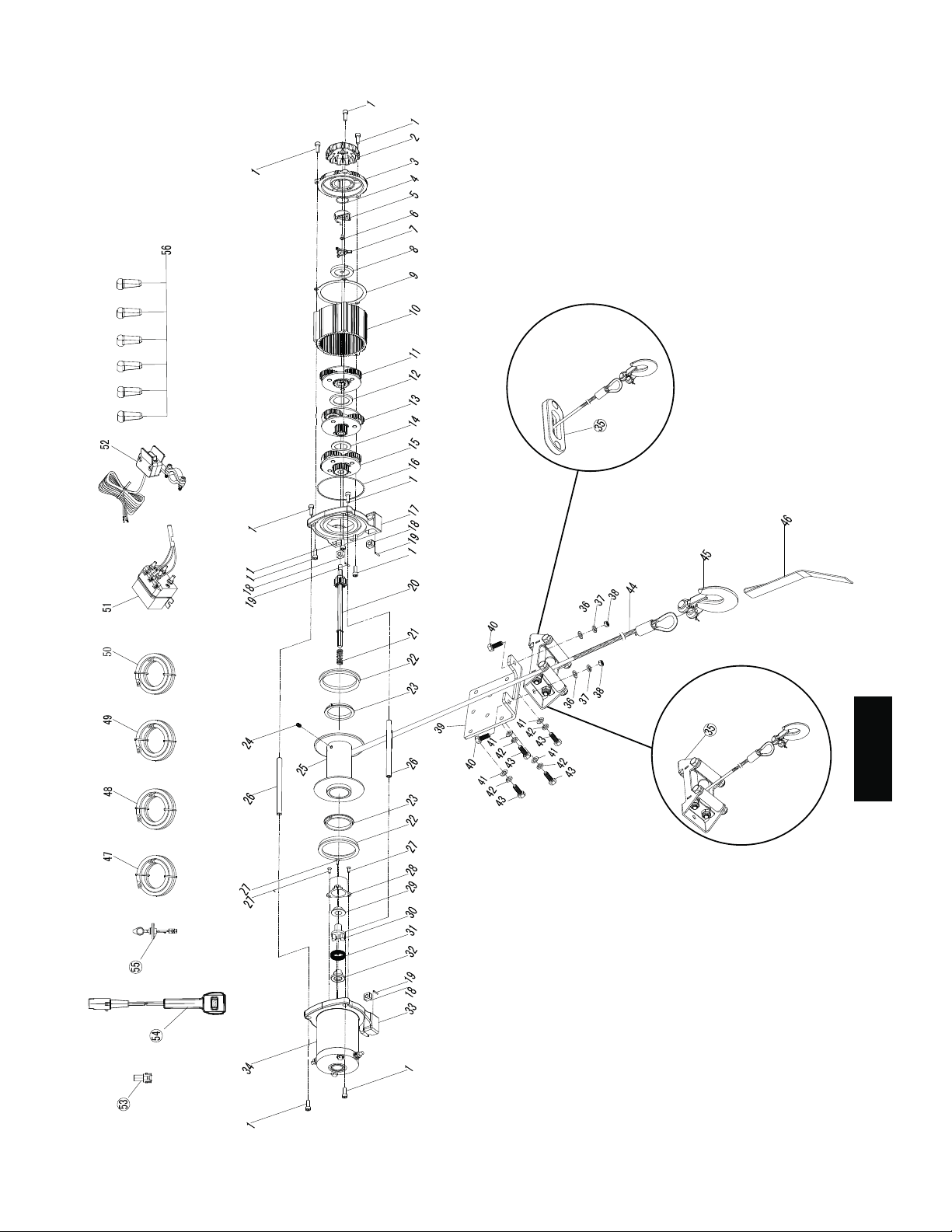
Parts List W35B and WS35B
14
ROLLER FAIRLEAD
APPLICABLE FOR
WIRE ROPE WINCH
ALUMINIUM FAIRLEAD
APPLICABLE FOR SYNTHETIC
ROPE WINCH
4500lb
Parts List W45B and WS45B
15
ROLLER FAIRLEAD
APPLICABLE FOR
WIRE ROPE WINCH
ALUMINIUM FAIRLEAD
APPLICABLE FOR SYNTHETIC
ROPE WINCH
English

Parts List W35B and WS35B
Replacement Parts list
Parts List W45B and WS45B
No. Description Qty
1Socket head screw 4
2Clutch knob
1
3Socket head screw 4
4Gear box
1
5
6
7
Nut
O Ring
Clutch knob base
4
1
1
8
9Screw
Fork pin 1
1
10 2nd stage planetary gear 1
11 Spacer 1
12 3rd stage planetary gear 1
2
2
4
2
13
14 O Ring
Gear box cap
15 Nut
16 Nylon bearing
Seal
Drive shaft
Spring
Screw
Tie bar
Drum
1st stage planetary gear
Screw
Brake caliper
Spring
Brake base
Brake house
Gearbox (motor side)
Motor Assy
Mounting plate
Bolt
Washer
Lock washer
Nut
Wire rope
Hook 1/4
Washer
Lock washer
Bolt
Power lead red
Power lead black
Power lead bule
Power lead yellow
Connector Assy
Control handle
Plug-in components
Solenoid
Mini rocker switch
Brush
Hand strap
Locating ring
Clip
2
1
1
1
1
2
1
1
6
1
1
1
1
1
1
2
1
2
2
2
1
1
4
4
4
1
1
1
1
1
1
1
6
1
6
1
1
1
17
18
19
20
21
22
23
24
25
27
28
29
30
31
32
33
34
35 1
35
36
37
38
39
40
41
42
43
44
45
46
47
48
49
50
51
52
53
54
26
No. Description Qty
1Socket head screw 10
2Clutch knob
1
3Cover of gear box 1
4O Ring
Screw
Fork pin
1
5
6
7
Clutch knob base 1
1
1
8
9
Inner supporter
Gasket ring 1
1
10 Ring gear 1
11 1st stage planetary gear 1
12 Bulkhead
Bulkhead
1
1
1
1
1
13
14 2nd stage planetary gear
15 3rd stage planetary gear
16 O Ring
Gear box base
Nut
Shaft Assy
Spring
Gasket ring
Nylon bearing
Screw
Drum
Screw
Brake house
Brake caliper
Locating ring
Spring
Brake base
Gear box (motor side)
Motor Assy
Washer
Lock washer
Nut
Mounting plate
Bolt
Washer
Lock washer
Nut
Nylon rope
Hook 1/4
Hand Strap
Power lead red
Power lead black
Power lead bule
Power lead yellow
Mini rocker switch
Solenoid
Plug-in components
Control handle
Tie bar
Elastic pin
1
1
4
4
1
2
2
1
1
3
1
1
1
1
1
1
1
2
2
2
1
2
4
4
4
1
1
1
1
1
1
1
1
1
1
1
2
1
17
18
19
20
21
22
23
24
25
27
28
29
30
31
32
33
34
35
Fairlead - ( Applicable for synth rope )
4
1
4
1
4
1
1
1
1
1
1
1
2
2
4
2
2
1
1
1
1
2
1
1
6
1
1
1
1
1
1
2
1
2
2
2
1
1
4
4
4
1
1
1
1
1
1
1
6
1
6
1
1
1
1
Roller fairlead - ( Applicable for wire rope )
Fairlead - (Applicable for synth rope)
Roller Fairlead-(Applicable for wire rope) 1
35
36
37
38
39
40
41
42
43
44
45
46
47
48
49
50
51
52
53
54 Connector Assy
Brush 1
6
55
56
26
- Applicable
WA025
WA026
WA027
WA028
WA029
Part No. Description W35B WS35B WS45B
W45B
Remote control
Solenoid
Handlebar rocker switch
Synthetic rope
Synthetic rope
WA030
WA031
WA032
Wire rope
Wire rope
Roller fairlead
WA033
WA034
WA035
WA036
WA037
Part No. Description W35B WS35B WS45B
W45B
Aluminum hawse, black
Cables set
Mounting plate
Forged hook
Mounting hardware set
WA038
WA039 Motor
Motor
16

Limited Lifetime Warranty For Mechanical Components
Limited One (1) Year Warranty For Electrical Components
Keystone Automotive Operations, Inc. (“Keystone”) warrants the original purchaser that (a) the
mechanical components of any TrailFX winch will be free of defects in material and workmanship
for the lifetime of the winch, and (b) the electrical components will be free of defects in material
and workmanship for a period of one (1) year from the original date of purchase. This Warranty
applies only to the original purchaser of the winch. To obtain any warranty service, you must provide
Keystone with proof of purchase and date of purchase deemed as acceptable to Keystone, such as a
copy of your original purchase receipt. This Warranty does not cover the removal or re-installation of
the winch. Keystone will, at its sole option, repair, replace or refund the purchase price of a defective
winch or component, provided the defective winch or component during the warranty period is
returned, transportation charges prepaid, to Keystone. Attach owner’s name, address, telephone
number, a description of the problem, and a copy of your receipt or original bill of sale bearing the
Keystone serial number of the defective winch and date of purchase.
This Warranty does not apply to (i) to finish, synthetic rope or wire rope; (ii) if the winch has been
damaged by accident, abuse, collision, misuse, modification, misapplication, overloading, improper
installation or improper service; or (iii) any normal wearable part. This Warranty is void if the serial
number has been removed or defaced. Commercial or industrial use or application, or any hoisting
application of the winch voids the Warranty.
THE WARRANTY SET FORTH ABOVE IS THE ONLY WARRANTY. THERE ARE NO OTHER
WARRANTIES, EXPRESS OR IMPLIED, INCLUDING BUT NOT LIMITED TO IMPLIED WARRANTIES OF
MERCHANTABILITY OR FITNESS FOR A PARTICULAR PURPOSE. ANY IMPLIED WARRANTY WHICH
BY LAW MAY NOT BE EXCLUDED IS LIMITED IN DURATION TO ONE (1) YEAR FROM THE DATE OF
ORIGINAL RETAIL PURCHASE OF THE PRODUCT.
No Keystone dealer, agent, or employee is authorized to make any modification, addition or extension
to this Warranty.
KEYSTONE SHALL NOT BE LIABLE FOR SPECIAL, INDIRECT, INCIDENTAL OR CONSEQUENTIAL
DAMAGES (INCLUDING, BUT NOT LIMITED TO, LOST PROFITS, DOWN TIME OR LOSS OF USE) UNDER
ANY LEGAL THEORY, EVEN IF KEYSTONE WAS ADVISED OF THE POSSIBILITY OF SUCH DAMAGES.
Some states do not allow the exclusion of implied warranties of the exclusion or limitation of liability
for incidental or consequential damages or limitations on how long an implied warranty lasts, so the
above limitation or exclusion may not apply to you. This Warranty gives you specific legal rights. You
may also have other rights that vary from state to state.
Keystone reserves the right to change product design without notice. In situations in which Keystone
has changed a product design, Keystone shall have no obligation to upgrade or otherwise modify
previously manufactured products.
To submit a warranty claim or inquiry, or technical support or warranty information contact:
Keystone Automotive Operations, Inc.
44 Tunkhannock Avenue, Exeter, PA 18643
1.866.638.4870 • E-mail: [email protected]
To return product for warranty service contact:
1.866.638.4870 • E-mail: [email protected]
17
English

1
1
Treuil
Manuel d’utilisateur
Francais
1
This manual suits for next models
1
Table of contents
Languages:
Other TrailFX Winch manuals


