+-
1kΩresistor
Controlling the Feather
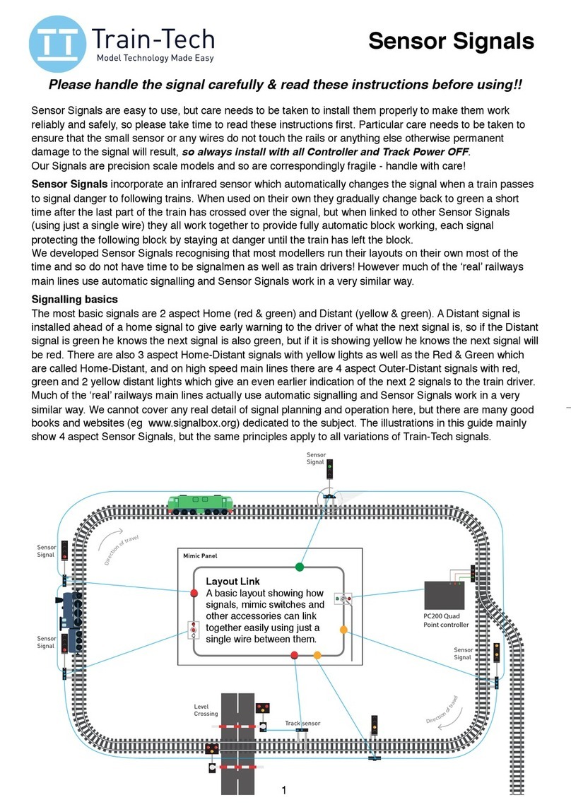
This route indicator can be wired and controlled in
3 main ways:
1) Using a switch on a control panel
2) Using a switch as fitted on some points
3) From a suitable DCC decoder (eg SC2)
Wiring the Feather
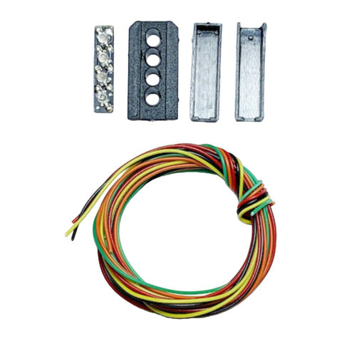
The diagram below shows the 3 components
which go to make up the feather.
However before fitting it together you should
solder your connecting wires onto the feather.
Some types of signal may allow you to pass the
wires inside the signal post as well as the existing
signal connections, though you will need to use
quite fine insulated wire to be able to do this.
Or you can fix the wires down the back of the
signal head and post hidden from view.
All 5 white LEDs are already connected together
in parallel on the PCB so there are just two solder
connections to make, one on the front (+) (where
LEDs are mounted) and one on the rear (-) as
shown below. Note polarity is important with LEDs
and always use a resistor in series to prevent
damage - refer to the Using LEDs advice below.
When soldering the wires onto the PCB contacts
pre-tin the wires first and be careful not to apply
too much solder to keep the connections slim.
LK1 Left Feather add-on kit
CAUTION - ALWAYS SWITCH OFF POWER TO YOUR LAYOUT BEFORE CONNECTING OR DISCONNECTING ANY ACCESSORIES
This kit contains the components to retrospectively add a left feather to an OO/HO gauge colour light signal - reasonable craft skills
including gluing and soldering will be required.
Introduction
Contents
1 Feather circuit board (PCB) with 5 fitted LEDs
1 Front feather cover with light cowls
1 Back feather cover
1 1KΩresistor (Colour: Black Brown Red Gold)
1 Instruction leaflet
You will need
Soldering iron with small tip
Flux cored solder
Plastic Adhesive
Pair of fine wires to connect the feather
Magnifier
Cutting mat
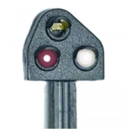
A Feather is a route indicator fitted to the top of
some colour light signals, usually located just
before a point and which lights when a point is
set in the direction of the feather to show the
driver the route he will be taking.
DC, DCC and automatic signals are available in
the Train-Tech range with route indicators
prefitted and wired, but this kit allows a route to
be added retrospectively to Train-Tech or other
makes of signal. Note that reasonable modelling
skills will be required to mount and connect this
route indicator to existing signals.
You can either control the Route indicator using
conventional switches or connect it to a DCC
decoder (eg Train-Tech SC2) to control it from a
Digital controller or computer. You can also
connect the feather to the switch fitted to some
points so that it lights automatically when the
point is in the same direction.
Take extra care when using
tools and adhesives.
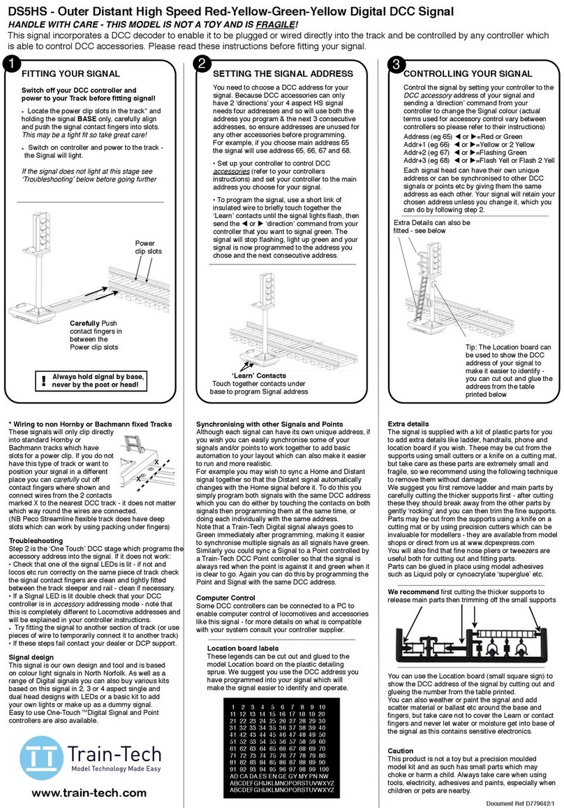
-
12-16
V DC
Wiring example for switches
The wiring diagram below shows how to connect a
switch and this example is suitable for either a control
panel switch or a point switch.
©DCP 2018 Document Ref D779679RK
+
Route switch
Before gluing the front and back case together
around the light PCB you can test it using a 12 V
DC supply or a 9 volt battery - do not forget to
use the resistor in series with one of the wires!
Once tested you can trim around the mouldings if
necessary and glue the front and back together
to make the complete feather to mount onto your
signal. The tab fitted to the back cover may be
cut off if not required to fix to the signal.
Cut off
mounting tab
if not required
Feathers are normally located on signals just
before a point so if a point switch is included on
the point motor or you can add a point switch to
the motor (eg Peco PL13) and the advantage is
that the route indicator will light automatically
when the point is in that position.
Remember to always use a resistor when wired to
a DC voltage supply in this way.
Controlling from a DCC decoder
If your layout points are electrically controlled
using DCC, then a decoder can be set up to turn
on the route indicator when the point is set to a
particular direction. Check the decoder
instructions to see if you need to fit a resistor in
series with the LED (note that Train-Tech
decoders have a built in resistor).
Using Signals with Train-Tech DCC controllers
Train Tech manufactures various LED controllers including
the SC1 and SC2 DCC colour light signal controllers which
allow signals with LEDs to quickly and easily connect to
DCC layouts for control by Digital controller or computer.
The SC1 is a dual 2 aspect controller and the SC2 is a 3 or
4 aspect plus route indicator controller.
Like all of our One Touch™DCC products they are quick to
connect needing no resistors or soldering and set up in
seconds with no programming of CV codes.
Assembled Digital Signals with DCC decoders built into the
base are also available which just clip into the track with no
wires or you can connect to the nearest piece of track
using 2 wires.
As well as DCC signals and controllers, Train-Tech also
makes a range of LFX LED lighting controllers which work
on both DC and DCC and offer effects to simulate level
crossings, welding, traffic lights etc - again resistors are
built into all of the LFX units and so LEDs connect directly
to them.
Train-Tech offers packs of various LEDs for modellers and
these come with both instructions and suitable resistors for
using them on a standard DC supply or non Train-Tech
DCC controllers.
See www.train-tech.com for full details of our range or ask
for the latest free Train-Tech brochure.
Using LEDs with model railways
You can use various types of lights for your signal,
but we recommend LEDs as the best choice for
models. LEDs are really useful lights which, unlike
their conventional filament predecessors, are robust,
low power and if used correctly run cool and can
effectively last forever. But there are some important
considerations when using LEDs. Firstly LED stands
for Light Emitting Diode and a diode is an electronic
component which only works in when power is
applied in one specific direction, so they always
need to be fitted the correct way round to work
correctly. Also most standard miniature LEDs a
modeller will use only need a very small amount of
power, so the current flowing through the LED must
be limited and this is usually done by a resistor.
On the usual 12-16 volts DC supply a railway
modeller uses a 1kΩ(one thousand ohms) will limit
the current to around 10-14mA (mA is thousandths
of an amp) which is ideal for most LED’s.
Note you should only ever use LEDs on a DC (direct
current) supply and never an AC (alternating
current) supply because although the LED may
appear to work properly constant reversal of voltage
using AC will eventually damage or shorten its life.
Connecting LEDs
As explained previously LEDs have a polarity and
must be connected the correct way round to light.
The most popular LEDs come in 3mm and 5mm
diameter cases and look similar to this:
The best indication of polarity on this type of LED is
to find the flat side on the round base. This side
usually indicates the negative (Cathode) connection
and the other wire the positive (Anode) connection
to power.
Another really small LED we supply for some Train-
Tech products looks like this:
There are many LEDs available and it is good to
experiment, but check data for specific connection
information as there are no real standards.
FLAT
SIDE
+-
+-
FLAT
SIDE


